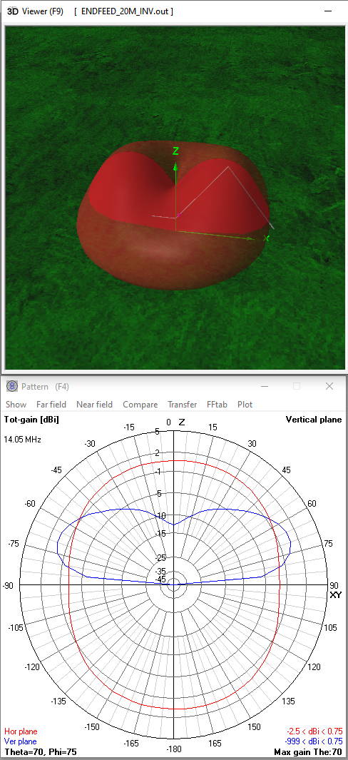
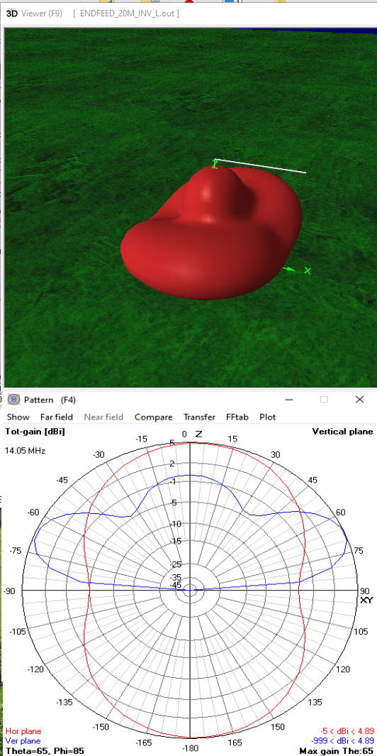
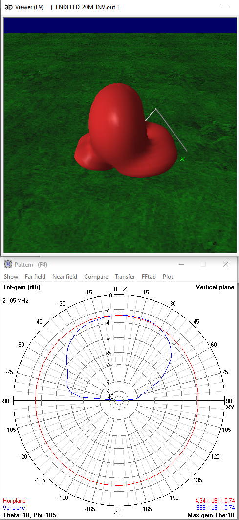
In the occasion of the Trans-Alantic S2S, I calculated the diagrams for a 20m long end-fed wire.
In my preferred way as inverted V and in that of Stephan HB9EAJ as inverted L.
Stephan, I like your suggestion a lot better, except for 10m.
73 Chris
20m Inverted V ------------------------ Inverted L
Thanks and congratulations to all those who can arrange the horizontal part of the inv-L on a summit really horizontally (and in addition in the advantageous direction).
Thanks Chris for comparing the inv-V against the inv-L patterns on different bands using a 20m long radiator and a 10m tall pole.
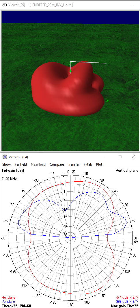
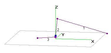
In my case, I’m lazy and usually just carry a 6m tall pole with me that mostly doesn’t need guying. Furter, the horizontal part is not straight, but goes down to about 2m above the ground. Easier and quicker setup and I can reach the 60m coil bypass switch without lowering the mast. That’s why I sometimes call this setup inverted-7:
(3 is the coax and 2 and 1 is the radiator)
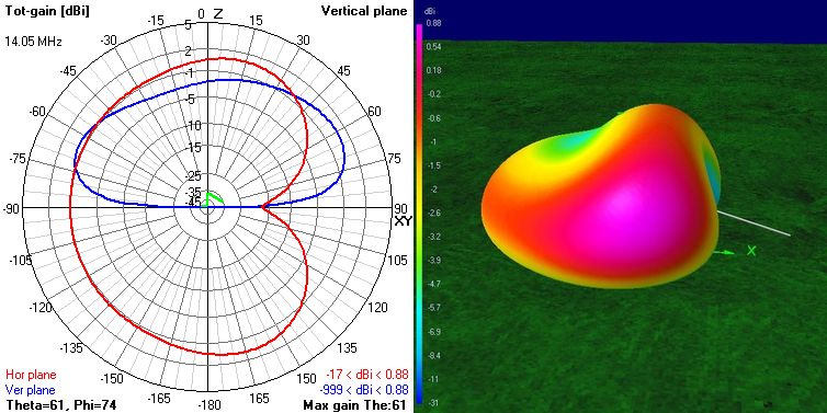
On the 20m-band, the resulting pattern looks like:
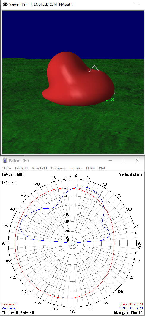
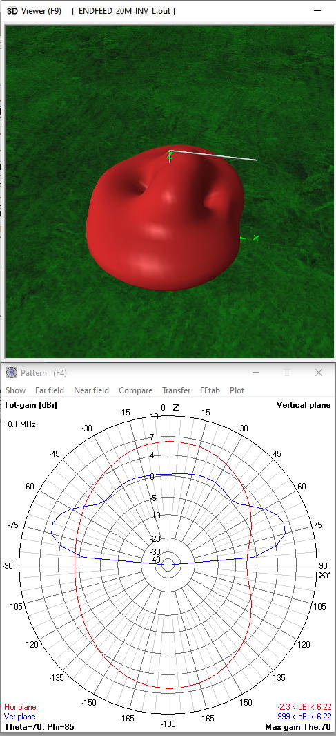
This looks a bit different than your “real” inverted-L, also because of the 3m additional height. I guess you also used a realistic ground. There is one null in my pattern that one has to be aware of and that I experienced several times.
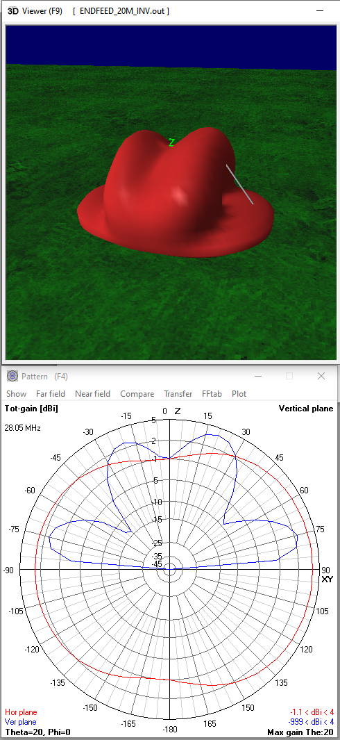
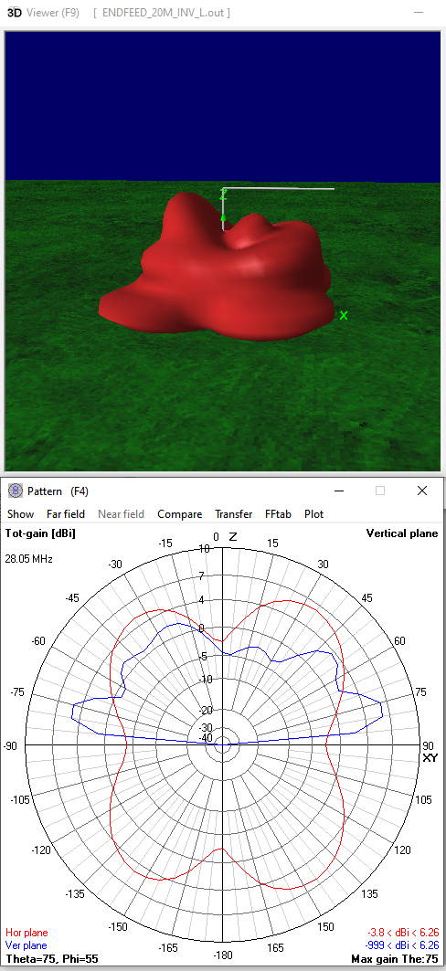
The 10m-band pattern looks not good and should be replaced with a max. 1 Lambda long radiator, if one has time and motivation (as described in the document).
For the upcoming Trans-Atlantic S2S party, a sloping surface in Europe with direction North-West will improve the pattern towards North-America a lot!
But this is a special event and as Heinz @HB9BCB mentioned, usually the summit dictates the setup.
Pardon my ignorance, but I had always thought the best direction of the inverted-L was in a direction generally looking toward the bend and away from the tail section, but your diagram seems to show the best gain in lobes 45° offset in the general direction looking toward the tail section. Simply put, do I aim the tail toward Europe?
73! Mike, WB2FUV
If you mean with the tail the (mostly) horizontal part, then no, since there is the null.
On a sloping hill, with the direction to NA from Europe, I will put the opposite side of the tail to NA. One could also orient it in about 30 degrees to the tail, there you’ll get maybe 0.5db more. One should definitely create a model that takes a sloping hill into account…
There is nothing mystical about it, only the vertical radiation angles calculated for a flat ground are reduced in one (desired) direction by the inclination angle of the hill. The radiation properties of the antenna relative to the ground remain unchanged.
But they will have a different angle, since there is the slope. The tail gets now uplifted and will look like a sloper. Let’s see how it behaves in reality, assuming the conditions will be fine.
Unfortunately wishful thinking because the antenna geometry and thus also the radiation properties remain unchanged relative to the ground. Therefore your antenna cannot easily mutate into a base fed sloper…
The only advantage of the arrangement on an inclined terrain is that this reduces the absolute vertical radiation angle by approximately the inclination angle of the terrain.
Either way, your antenna will be sufficient for NA s2s QSOs and the limiting factor will probably only be the competing QRO portable stations.
So good luck then.
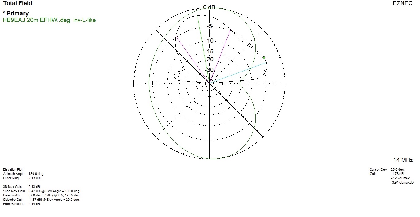
Just to complete the picture, the radiation properties at 180 deg, i.e. with the antenna alignment you intend to use.
Thanks for taking your time and trying to explain me your view. I have no time now to play with this buggy 4nec2. Also, I never played with different slopes of the terrain using this modeling software, so I just interpreted this sloping factor with my brain into my generated pattern, which may be wrong.
But when looking at your pattern, the slope makes the radiation towards NA even worse, that’s why I think we’re not on the same page, or I simply interpret your pattern wrong.
Anyways, two years ago, before I modeled a similar antenna, I didn’t know where the null was and even made at least one NA S2S contact using 5W SSB towards the null. I’ll be prepared to move the horizontal part of the antenna around and experiment with that in the field.
Hello Chris,
I try to retrieve your results in MMana. Can you precise the angle of your inverted-V (which seems to be greater than 90°), the height of the base of the antenna, and the length of the radial ?
TNX,
73 Nico
Sorry Stephan, I didn’t want to impose myself. The posted diagrams are not my point of view, but rather those of EZNEC over a flat ground and yes, you may have misinterpreted the horizontal and vertical diagrams placed one on top of the other.
And yes, there are both Ham myths and purely physical considerations about the influence of an inclined terrain on the radiation properties of an antenna (location of the latter is currently unknown).
Both segments are 10m long, top angels 73,74 deg
First element x1=0m h1=2m; x2=6m h2=10m
Second element x1=6m h1=10m; x2=12m h2=2m
Radial 3m long
73 Chris