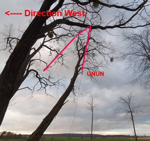
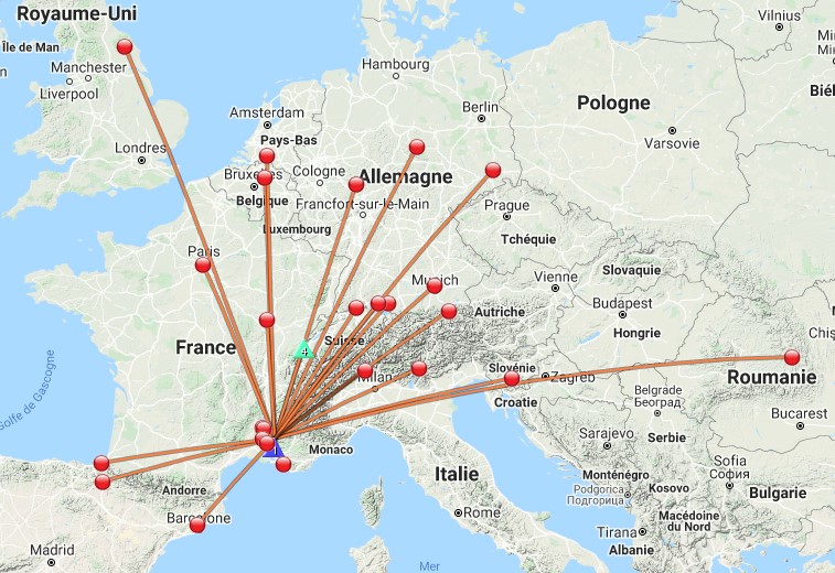
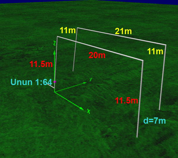
During my last POTA activation I had an unusual suspension of my 20m long EFHW. I call them DOOR.
Surprisingly, I could reach the Azores and North America, also in SSB with 10W on 17m and 20m.
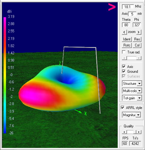
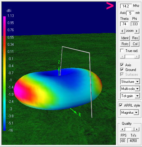
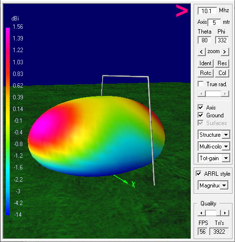
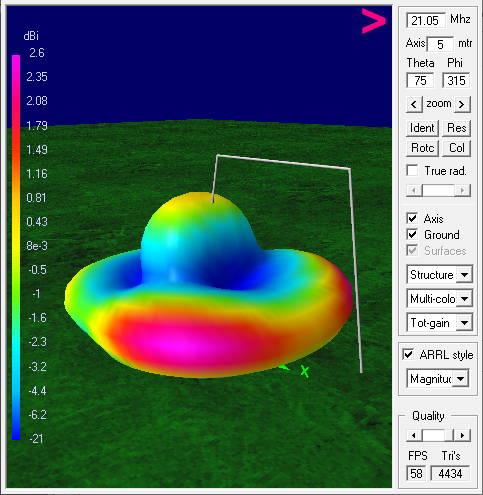
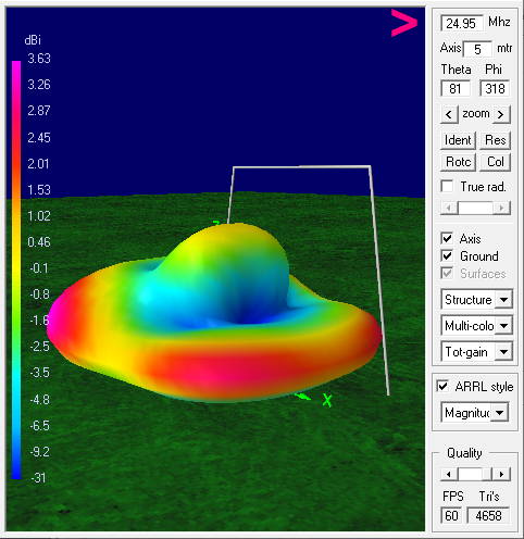
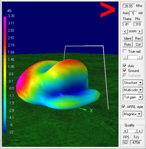
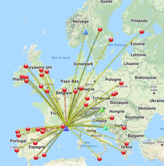
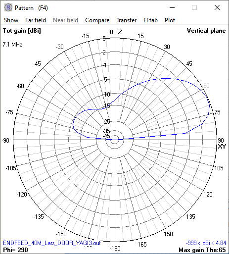
At home I calculated the radiation diagram. Except for the 10m I find the result quite convincing.
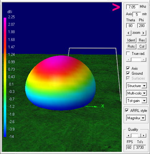
Directional gain radiation and satisfactory omnidirectional radiation. Near Vertical Incidence Skywave on 40m, not bad for Europe
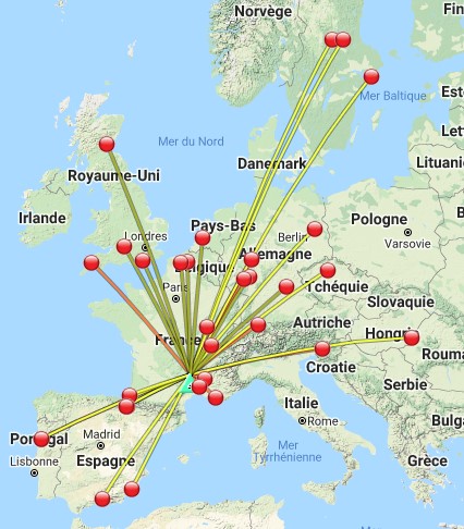
First 17m and 20m diagrams, then 40m, 30m, 15m, 12m and the ugly 10m.
All these diagrams are calculated wonderful and theoretical… and at best show tendencies.
I am afraid that in practice they always look quite different.
As you can see in your pictures, there are trees very close. I can well imagine that these trees will have influence on the diagram… although in winter maybe not so much as in summer.
Then, especially in SOTA, the ever-changing ground conditions are an issue. This is already to be read off from the SWR ratios to be achieved… e.g. over a snow surface
On the 09/08/2021 using my multi bands vertical JPC-7 on the ground (7 non elevated radials) FT-817nd 5w
Of course this comparison does not take into account the season and the propagation, but gives an idea of the radiation of the antennas used. Ideally, these tests should be done on the same day and on the same frequencies.
Correct Eric, it’s not too scientific unless it’s done at the same time. However, I find that I generally work the same stations on 20m and the same stations on 40m, no matter what wire antenna I use (inverted V, EFHW or W3EDP) Unless there are no sunspots or a solar flare. If I use more power, I just get better signal reports from the same guys. When I do get DX, it’s because the band is wide open, not because of my antenna. I’m using simple wires of course. Ones that are quick to erect and get on the air, which suits my style. Better results will be achieved by mire complex designs.
However, I do love reading antenna articles and trying new ones. Don’t we all?
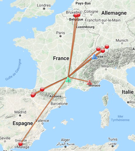
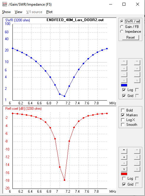
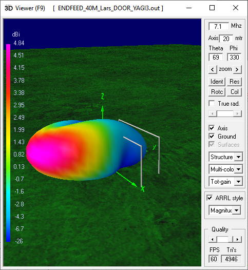
My friend Lars SA4BLM is asking me about a chaser 2 element yagi for 40m by wire. I did my EFHW DOOR as a basis. According to the simulation, a gain of almost 5db and 15db forwards/backwards.
Whether you get similar data in practice, I do not know. But it might make you want to try it yourself.
wonderful… if your mountain peaks are flat terrain and the ground conductive. Try the model with the antenna, say, 300 meters high, which I think is more realistic, at least it is for my peaks here in the Rockies… fred kt5x / ws0ta
Chris’ home summits are not that steep. Ground conductivity is sure less than average.
However, the sloping terrain may pull the main lobe a bit more to the ground, i.e. make the antenna even more DX’ish.
Pom, I think you’re underestimating the impact of the real ground on the vertical radiation pattern of any antenna. Any antenna significantly less than 2 wavelengths above ground will have an elevation angle significantly greater than 0 degrees.
This also applies to vertical antennas.
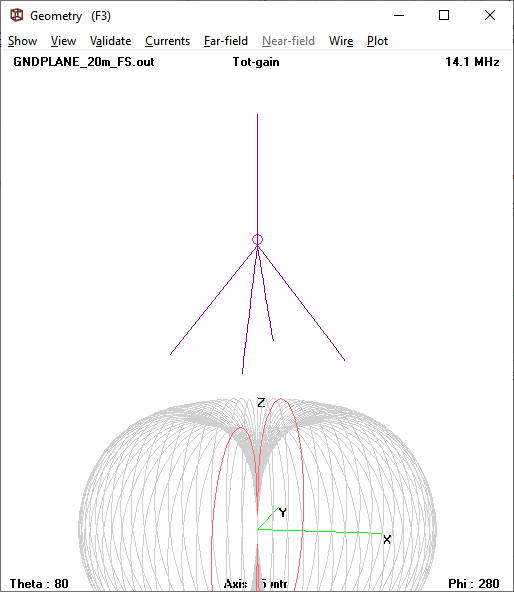
Here is an example of an optimal ground plane antenna for 20m with the feed point 10m above ground. This is certainly not easy to implement at a summit.
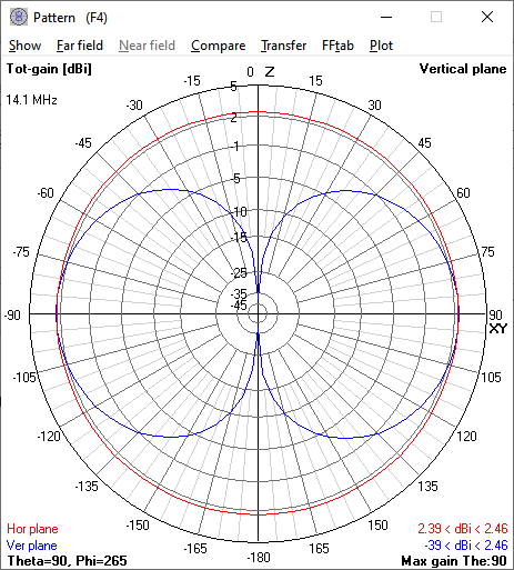
The first two images show the simulation in free space. The result shows the desired elevation angle of 0 degrees.
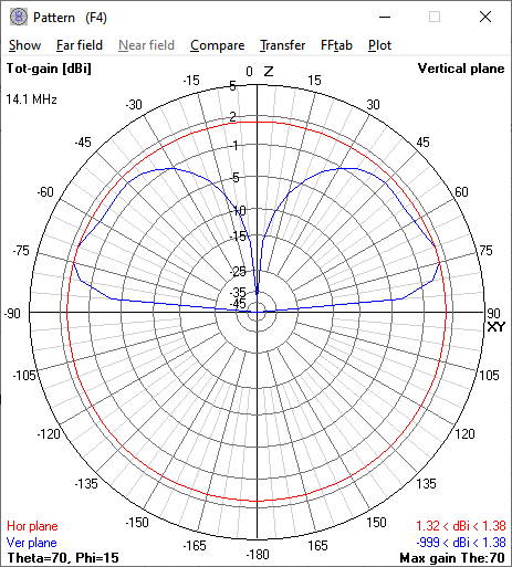
Then with real radiation pattern of the groundplane still 10m above ground!
I love this topic of Wire Antennas. Interesting on comparing both inverted V and End Fed L antennas.
I recently put up a end fed L with a wire of 44 ft. and testing it as compared to my Cushcraft R7 vertical that stands 15 ft above the ground. Yet the horizontal tail is about 20 ft above the ground, it seems to have less front end noise on my Icom 746Pro with an MFJ 949E antenna tuner. Most of the wire is horizontal and about 3 meters vertical above the Unun. The tail faces about 80 degrees from North. It sits on a tripod up 9 ft above the ground on the patio roof. Surprisingly enough I seem to make quite a bit of CW contacts
So I will save this thread for reading more about tests experiences, theories and propagation.
Thanks Guys es 73, KG7A