A SOTA Centric End Fed Half Wave Antenna (Part 1)

Ariel, I am pleased to see that your great persistence and curiosity to critically question the first test result and the conclusions drawn from it has paid off. Well done.

Please don’t be disappointed if I still make a small reservation. The radiation characteristic of your antenna is a bit special on the bands of 20-10 m and therefore no longer corresponds to that usually expected from a dipole.

Such a radiation characteristic is typical for all half-wave antennas whose relative height above the ground is low and whose relative antenna length is large (number of half-waves).
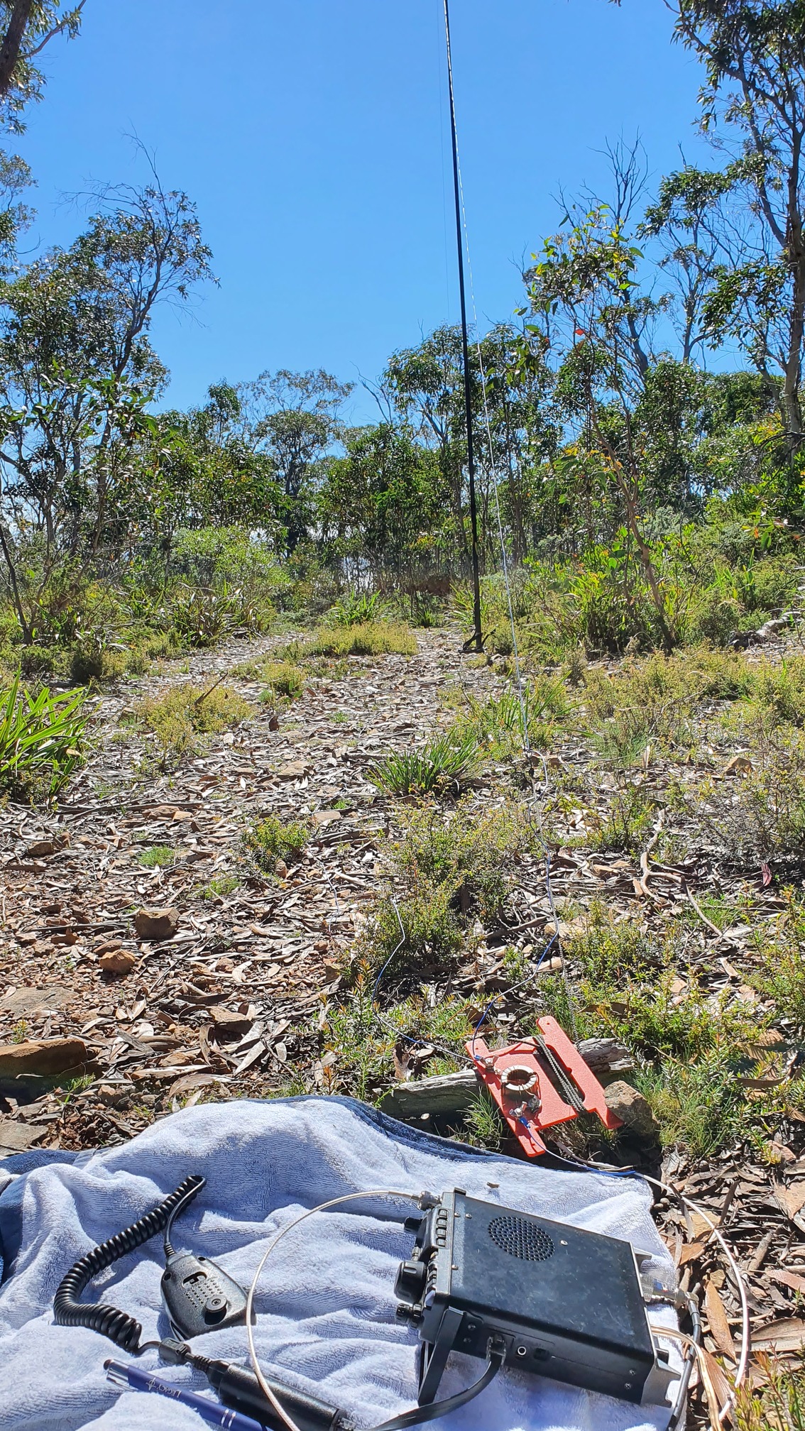
That’s why the short masts that SOTA enthusiasts like to use for practical reasons and half-wave antennas are not per se an optimal solution in terms of radiation properties.

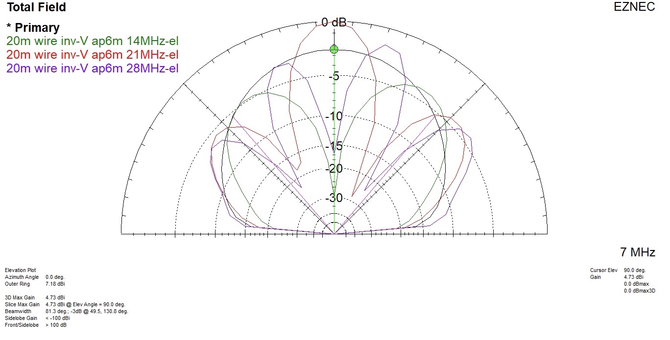
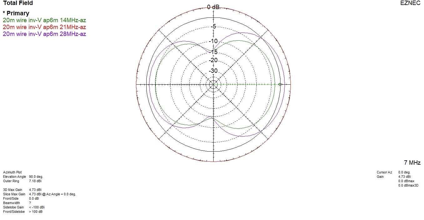
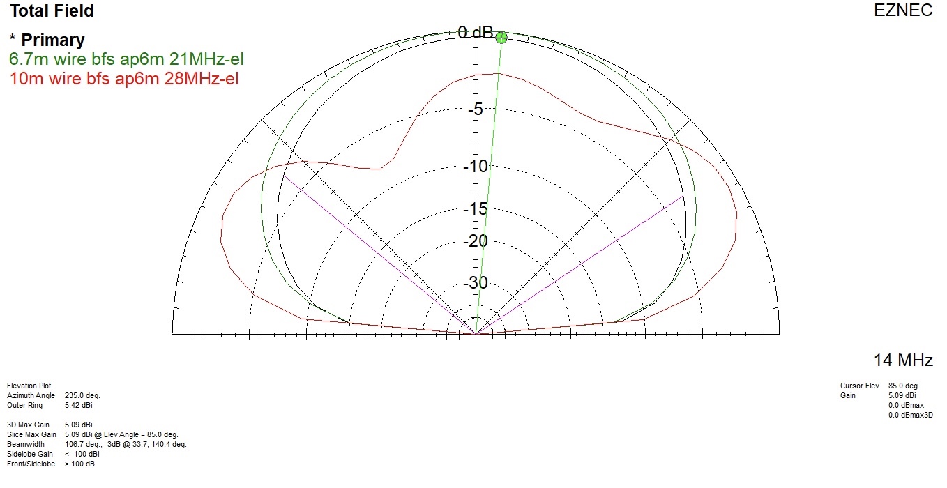
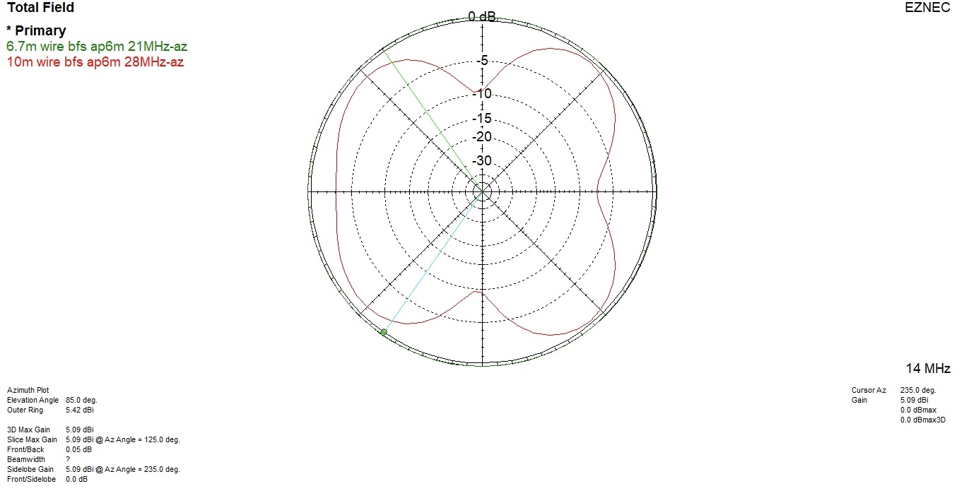
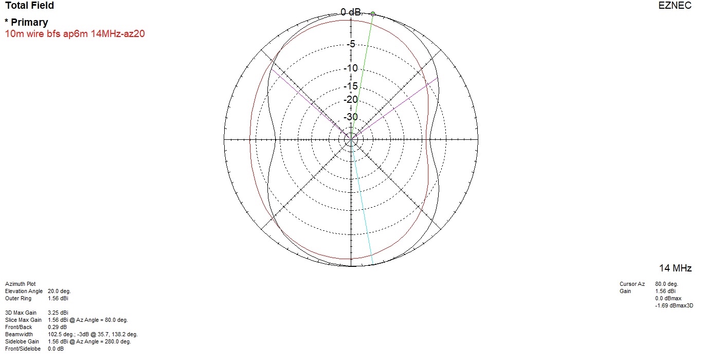
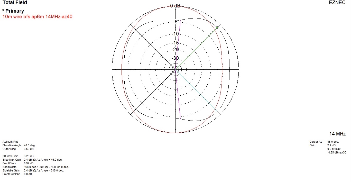
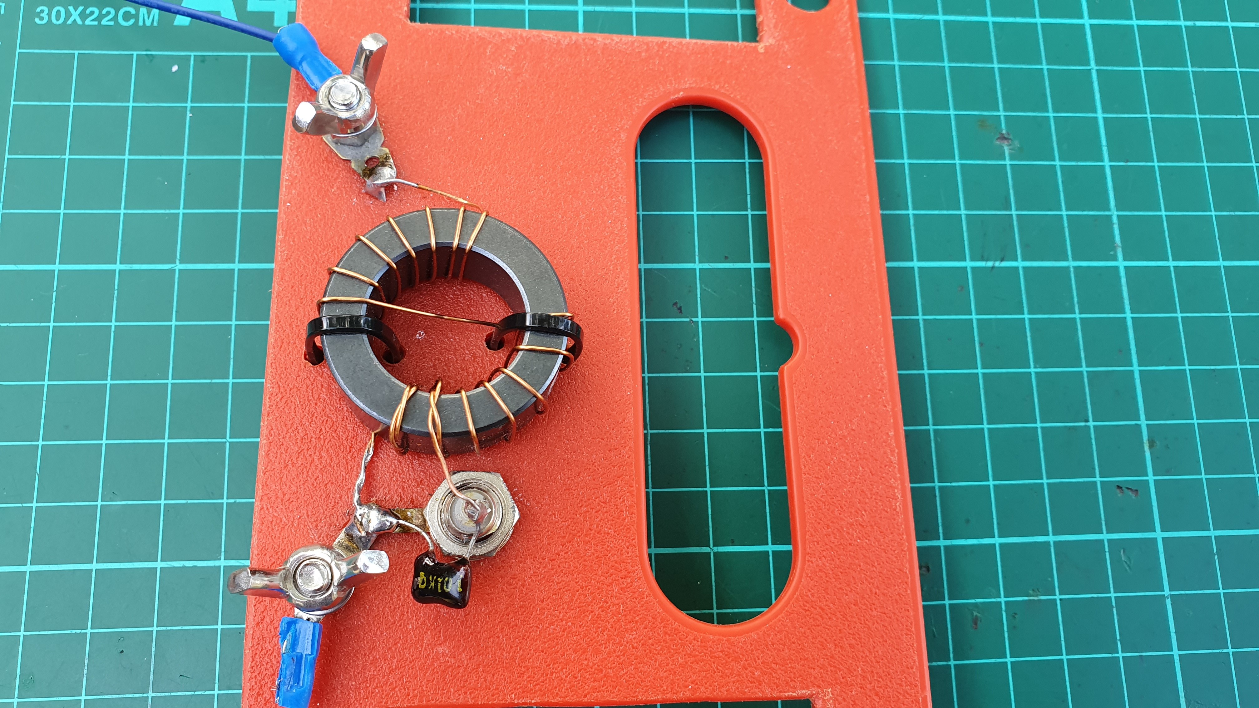
The radiation plots below show the radiation characteristics on 40/20/15/10 m of the SOTA centric EFHW with an apex height of 6 m and an apex angle of 130 degrees.
It is obvious that on 14 and 28 MHz this antenna does not radiate, as is generally expected, all around or on the broad side, but along its length.
This is why the unknown player during the WSPR test on 14 MHz could eventually also be hidden here and not only in the antenna separation in the sloping test area, hi.


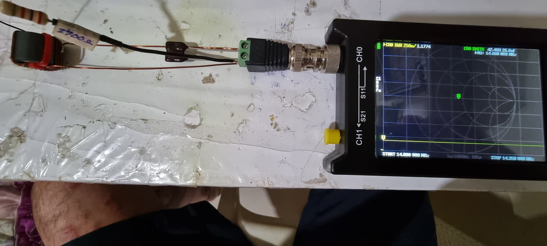
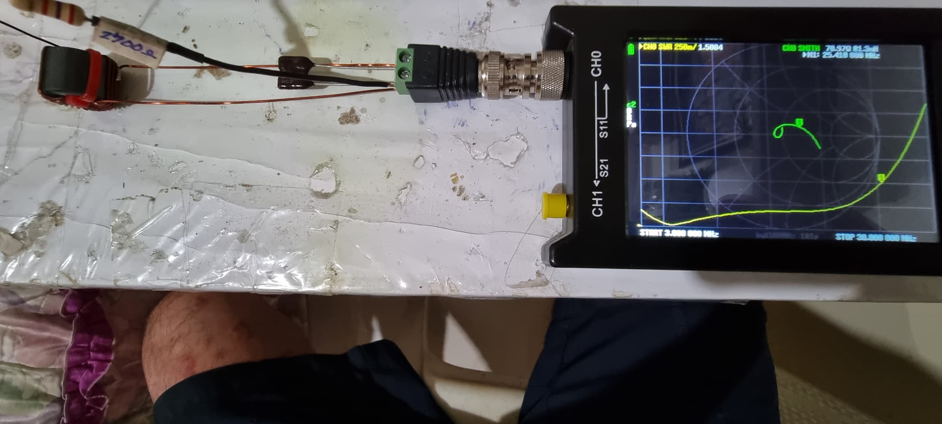
The different radiation characteristics of such a multi-band antenna cannot simply “tuned away” with an impedance matcher (VSWR), no matter how ingenious it is.

Or in other words: In any case, it is advisable to look at the entire system and not start with the gold plating at one end if it is rusting away at the other end …

Instead, an attempt must be made to reduce the relative antenna length and thus the number of multiples of half waves.

One possible solution could be (radiation plots below)

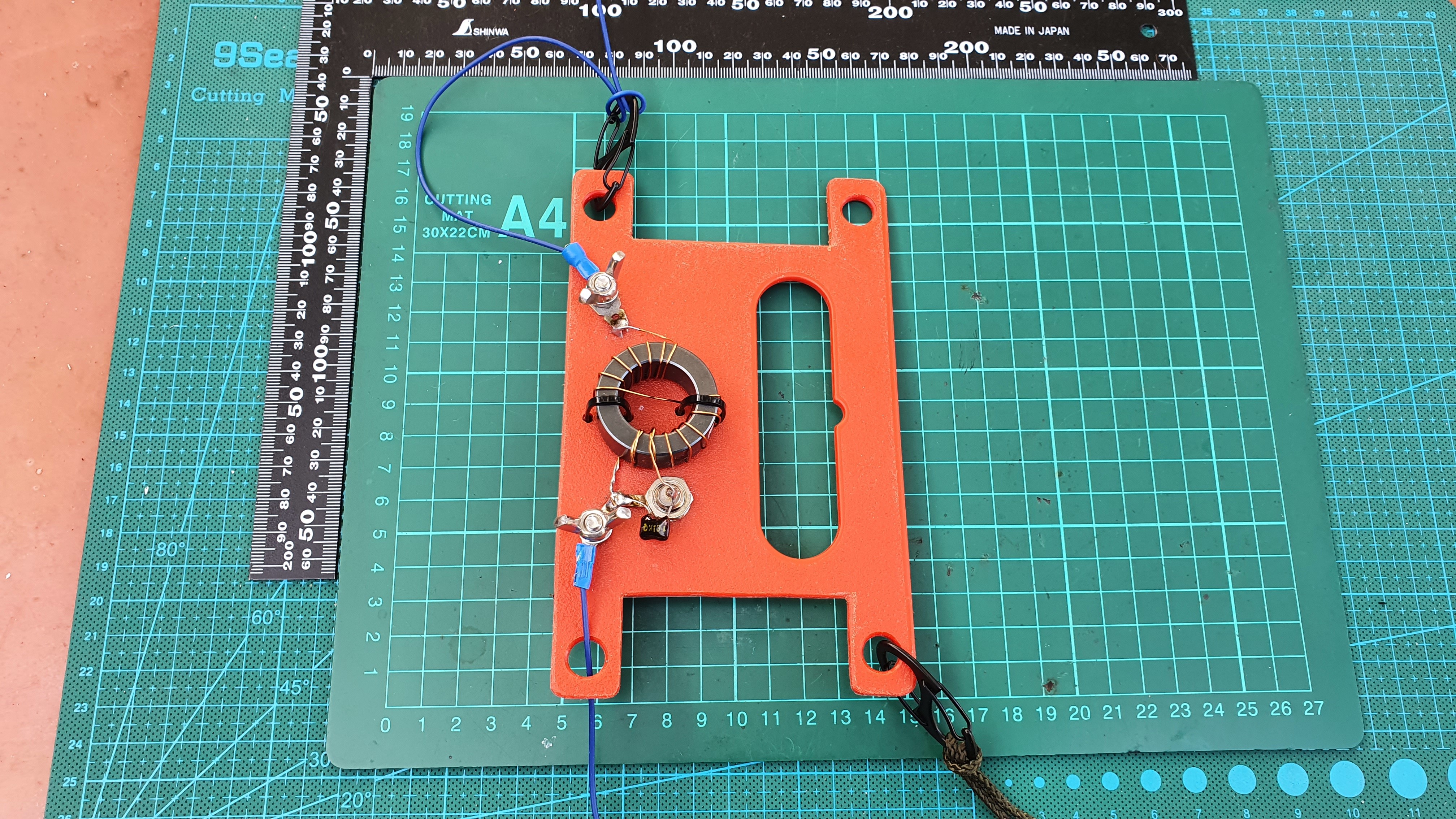
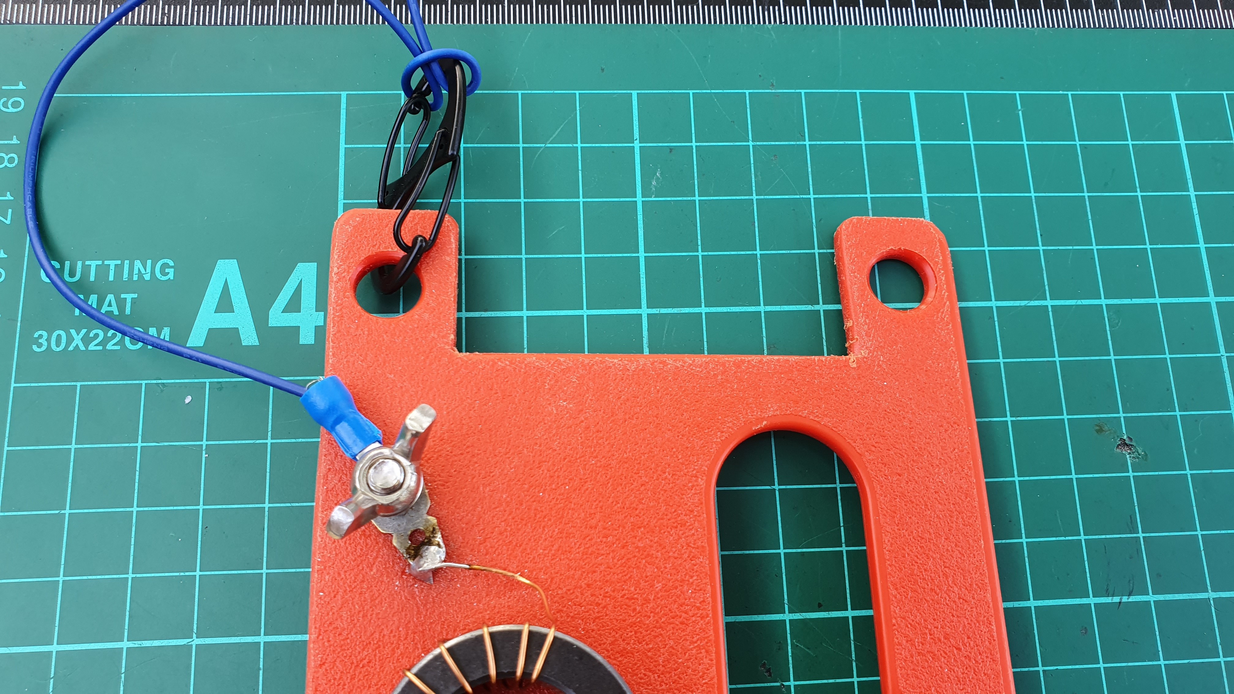
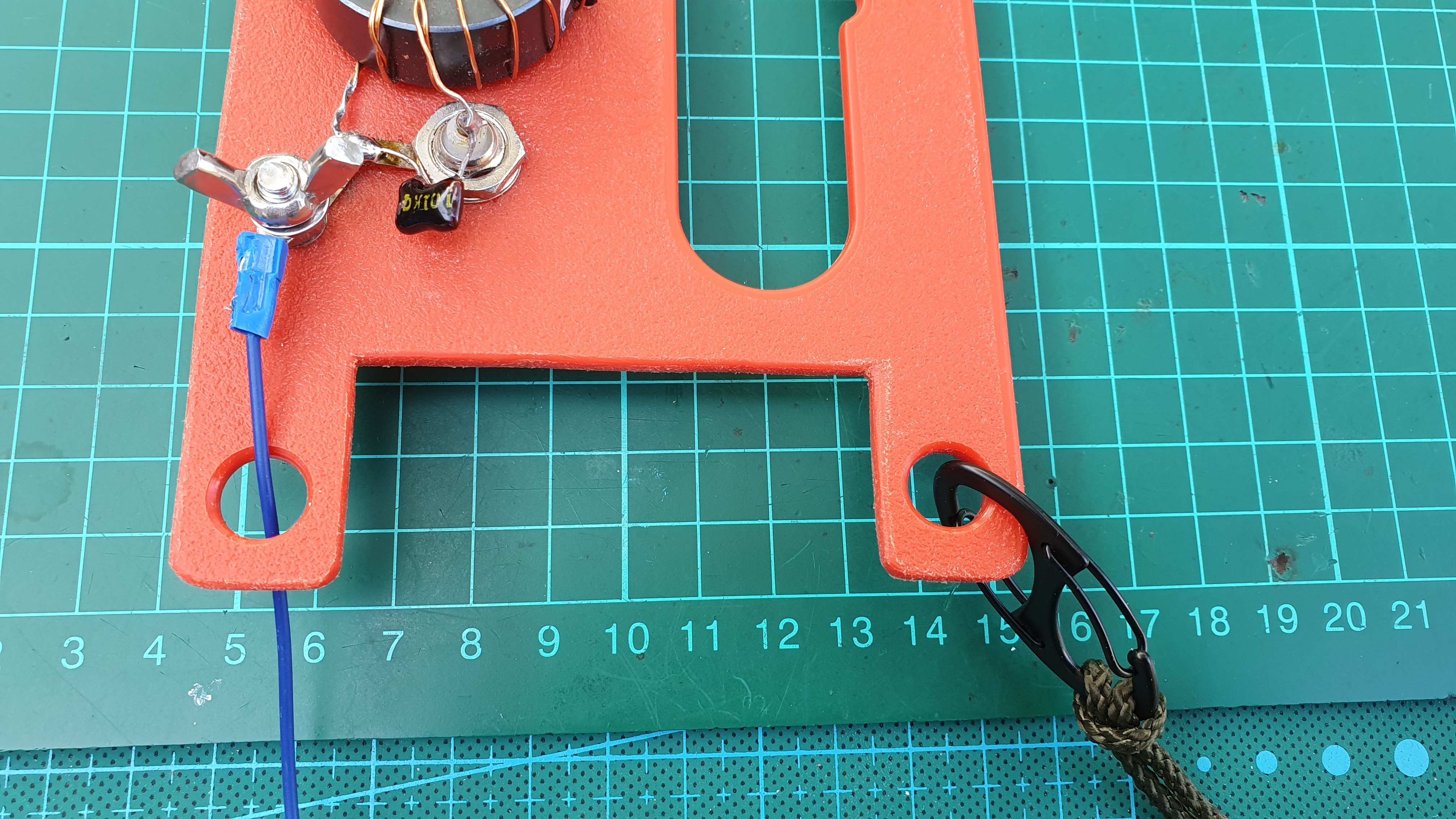
  • improvement on 14 and 28 MHz: an additional link for an EFHW on 14 MHz and use of this antenna length also for 28 MHz (2x 1/2 lambda). This would result in a base fed sloper (bfs).

  • improvement on 21 MHz: only possible with an additional link for an EFHW on 21 MHz (resulting also in a base fed sloper)


So I now hope that your SOTA centric EFHW will continue to give you a lot of pleasure, or even more so.

73 gl, Heinz

3 Likes

Heinz

Thanks for the suggestion and recommendation.

Very kind regards

Ariel NY4G

Thank you Ariel for doing all these experiments and providing us your data and conclusions!

As we see, it’s really difficult to compare two antennas or couplers exactly, even when using two concurrent WSPR transmitters.
There are simply too many error sources that can influence the outcoming result, but I think it’s good enough for our purpose.

@HB9BCB As you state correctly, in general, for a more flat and uniform radiation pattern it’s better to strive for a 1/2 lambda long EFHW wire, instead of using multiple half wave lengths.

But instead of setting up the antenna as inverted-V one can mostly improve the pattern until about the 2nd or 3rd harmonics by employing an inverted-L configuration. By doing so, one even needs less horizontal space.

Without running a modeling software, one can compare the patterns on several harmonics between (albeit for a 40m long wire, corresponding to an EFHW antenna for the fundamental 80 meter band):

  1. Inverted-V EFHW
  2. Inverted-L EFHW

Anyways, the summit environment influences the radiation pattern and also limits the possibilities of configuring the antenna setup.

73 Stephan

2 Likes

I agree with you here Stephan - hard to come to any hard conclusions because so many variable are involved. Just for “grins and giggles” I ran a short head to head WSPRlite test between identical couplers but one antenna radiating two half waves on 20m and the other a half wave sloper from the same inverted Vee (a trap at the 20m halfwave point). Here are the results just before the hour.

Ariel NY4G

1 Like

Below for information the radiation plots of the 2 compared antennas (az slices at el20 and el40 deg).

BTW, The statistics “Average of the 10 most distant receiving stations” are interesting, but do not paint a complete picture. For example, a statistic “Distance vs average SNR” taking into account all spots caused by an antenna would be also of interest.


2 Likes

Homebrew 49:1 EFHW using a FT140-43 core, 100 pf mica cap and 19.8 metres of wire. To help reduce RF on the coax feedline shield, I use a 6.8 metre counterpoise. Insulator is 3mm kitchen cutting board purchased from a mainstream supermarket. Cost for materials is $20.00 or you can pay $50+ postage at popular commercial sites.

Yesterday from VK2/ST-001 I worked VK2 and VK3 on 40m and VK1, VK4, VK5 and ZL stations, including two ZL S2S, on 20m all at 5 watts SSB. ZL path is ~2300 km.

VK1AD HF SOTA shack at Mt Cowangerong VK2/ST-001

73, Andrew VK1AD

10 Likes

Are you using RG174 coax? What’s the length?

That’s how I got my 10000 S2S points in 6 years. Without extra counterpoise line, instead with 10m RG174 coaxial as feed line and counterpoise.

And with the ATU from the KX2 on all 9 bands from 80m to 10m.

73 Chris

2 Likes

Heinz,

What type of Toroid can you recommend that has good efficiency characteristics to replace the FT240-43 and able to handle 100watts power output on SSB?

73’s
Jundy

1 Like

Jundy,

You have probably already read that to answer your question you cannot simply apply a simple rule of three calculation to resize a toroidal core for a specific criterion.

As Owen Duffy has repeatedly shown for years, the efficiency of an impedance transformer is determined by 2 main criteria

  • the quotient of the toroid cross-section and the mean field line length and

  • the magnetizing impedance created by the primary winding.

The calculated transformer efficiency for 2 stacked FT-140-43 cores with 3 primary turns is approx. 92%.

For operating modes such as SSB (and CW) 2 stacked FT-140-43 ferrite cores could just about suffice for a transmission power of up to 100 watts, but only if 3 primary turns are used.

Enamelled copper wire of 0.7 or 0.75 mm and a mica capacitor 100 pF/500 volts are recommended, as well as tight winding without gaps and short connecting wires from the transformer and capacitor.

Remarks
Impedance transformers with high coupling ratios in the range of 1:49 to 81 are suitable for use with half wave antennas or multiples thereof. If the wire length is precisely adjusted for a specific antenna geometry, it is possible to use several (harmonic) frequency bands without an antenna tuner.

When operating with random wire lengths, not only an antenna tuner is mandatory, the common mode currents that occur with high SWR could make the use of a common mode choke necessary (e.g. in the coaxial cable about 3m after the impedance transformer).

Many of these serious problems do not interfere with QRP transmit power and can therefore be neglected. If you know what I mean, hi.

73 gl, Heinz

3 Likes

I don’t think high SWR has anything to do with common mode current.

Hi Jundy,

I agree with the explanations and proposals of @HB9BCB.

If you only want to use one toroid core, Owen Duffy analyzed an alternative one with an interesting geometry: Another small efficient matching transformer for an EFHW – 2643251002 – #1 – design workup – owenduffy.net

In the last article about this core he makes a heat measurement with 50W carrier: Another small efficient matching transformer for an EFHW – 2643251002 – #3 – thermal measurement – owenduffy.net

73 Stephan

1 Like

I would like to point out that the losses depend significantly on the frequency.
From my experience, the FT140-43 Amidon with 100W SSB can be used from 10m to 40m without any problems. This only applies to EFHW antennas that are in resonance, e.g. a 20m long wire freely suspended on 40m, 20m, 15m and 10m.
The wire lengths of perhaps 22m or 25m, which are often used without hesitation, require a tuner and can cause the toroidal core to overheat at outputs of over 10W due to the reactive power.

73 Chris

1 Like

Yes, that is indeed an oversimplified statement that should not be left as it is.

In the present case of an EFHW transformer, an impedance mismatch is practically unavoidable if the very high-impedance antenna radiator is connected to the feed line impedance via the impedance transformer. This is not only reflected in the SWR value, but also allows a common mode current to flow on the outside of the coaxial screen (which also radiates and thus affects the antenna characteristics).
When connecting antenna radiators of random length or when operating EFHW radiators at random wavelength, this impedance mismatch and thus the influence on both the SWR and the common-mode current increases significantly.

2 Likes

Hello Heinz,

As i am currently digging for some other ways to improve my EFHW antenna set up for my fixed station, i was surprised to came across with these this new found investigation of Owen Duffy which was explained further by Stephan in his article posted and shared on facebook together with the persistent validation and work of NY4G in this forum and obcourse with the aid of your utmost collaboration.

I am now in my 10years of spending my spare time for this hobby and i am grateful for having this new found information as i am also in a process of having my next homebrew project for portable used.

Thank you much for the reply and guidance and i will be keeping you my update soon.

73’s
Jundy

1 Like

Yes Stephan and i will probably sticking with it and gonna have some homebrew these days.

Thanks & 73’s

can you make one for me pls

I have now with me the 2643625002 torroid from digikey arrived last friday for about 7days since i ordered it and as suggested by NY4G. I will be making the transformer per instruction in the link emailed by NY4G, a fellow Filipino living in the US😆. Hoping it will work as suggested in the discussion.


1 Like

:rofl: M6YLY you might just ended with an unfortunate finished product considering that i am a newby.:rofl::rofl:

2 Likes

Jundy,

In your previous post with the photos of the measurement setup, you didn’t ask a question. Nevertheless, I allow myself a few comments in the hope that these could be useful for you.

First to the wound Fair-Rite 2643625002 ferrite toroidal core: It is wound very tightly and on the inside without any space between the individual windings.
Congratulations on that.

The wire diameter appears a bit large on the photos (0.8 mm?). This results in a somewhat long winding, which has an unfavorable effect on the winding geometry (increased flux leakage).

BTW, in the secondary winding of an EFHW transformer, only a current that is reduced by the turns ratio compared to the primary winding flows. With a 1:49 transformer, for example, this is only about 80mA at 15 watts.

Now to your measurement setup: The data obtained with it undoubtedly and unfortunately follow the GIGO law (garbage in garbage out).

This is because the calibration reference plane (on the VNA) does not coincide with the measurement reference plane (on the EFHW transformer) - and because it is practically impossible to measure the relevant properties of the “wire loops” in between and to take them into account in the measurements. The characteristic values ​​of these “wire loops” also change greatly, depending on their geometry and position in relation to the immediate environment (e.g. lying on the workbench or floating).

So for the measurement of the transformer characteristic values, its connecting wires should be kept as short as possible, as can be seen, for example, from the measuring arrangement I usually use (photo below).

The second photo below shows the result of a measurement made on a 1:64 EFHW Transformer with this ferrite core. The ferrite core is chosen at random from a number of, for now, about 50 (…), but the measured transformer efficiency of about 88% is not significantly below the value predicted by calculation.

And last but not least, the measurements with a purely resistive nominal load only say something about the selected design of an EFHW transformer. If the transformer is built into a housing and even more so if connected to a real EFHW, the results will differ.

73 gl, Heinz


5 Likes