BTW, What you see again and again are the slightly inappropriately selected versions of the compensation capacitors.
I can only explain it to myself that this is either due to a lack of knowledge of the requirements or a lack of available crafting budget.
Stability requirements
High stability and low loss (low relative permittivity) is required because the value of the compensation capacitor has a significant influence on the relevant characteristics of the impedance coupler.
Suitable capacitor types are therefore:
(Silver) Mica
Ceramic Class 1 C0G (NP0)
Electric strength requirements
The required electric strength depends on the voltage across the primary winding of the coupler. With a transmission power of 100 W over the system impedance of 50 ohms, a voltage of slightly less than 90 V would build up.
Suitable electric strengths (with plenty of reserve for unexpected cases…) are therefore:
250 V for transmission powers up to approx. 50 W.
500 V for transmission powers up to approx. 150 W
And yes, the connection wires of the compensation capacitor should be as short as possible (i.e. no longer than about 5 mm if possible).
I appreciate your work in this area and always read your posts with interest. I would add some comments especially with your references to the work published by Owen Duffy vk2omd ex vk1od, who I have known for some years possibly over 40…
The use of a .05 wavelength “counterpoise” is, I think quite often seen, whereby a piece of wire roughly in line with the antenna is labelled “counterpoise” but if that antenna was compared with an offcentre fed half wave, with the feed point positioned at the 95%:5% point, there would be plainly no difference between these two antennas. So the so-called end fed with a 5% counterpoise can also be called (or some may say, is actually) an offcentre fed half wave.
This point is hinted at by Owen Duffy’s referenced article. Owen doesn’t like to labour his points, he wants readers to ponder the salient facts and come to the right conclusions about them.
The other very salient point he makes about such antennas is that the current at the “fed end” of it is not zero, it is just “low”. If there was no current, there would be no way for the antenna wire to create the fields that make it radiate. And therefore there is a corresponding opposite current in the other part of the antenna, the tail, counterpoise or 5% bit, or in the outer of the feed coax, operator, mike, key and radio, or all of the above. Placing a suitable choke on the feedline would soon determine whether the current there was essential to the matching system.
I also have noted end fed antennas that are not resonant. I don’t see how the reactance of that antenna cannot interfere with the intended operation of the transformer or coupling circuit. Reactance changes transformer operation, especially those with ferrite cores.
Thanks for the comment, which fully coincides with my understanding of this matter.
If I was not understood correctly and, oh dear, Stephan did not quote me fully in my mind, it may be because I try not to preach again in detail what the whole world already knows.
Another reason for this could be that the meaning of the punctuations I used among colleagues, such as “” and hi and (?), are meaningless for the general public.
So, if I put “counterpoise” in quotation marks and the quote of 0.05 Lambda “counterpoise” Ham myth ended with the punctuation (?) in a previous post, I would indicate the questionable nature and not express my consent.
To keep myself brief, I therefore referred to the relevant findings by Maxwell, Roy Lewallen (EZNEC) and Owen Duffy. From the expert’s point of view, everything should be clear, provided you have understood what you have read.
If, as in the articles below, an attempt is made to solve or alleviate the so-called “problem” by inserting a common mode choke, this is merely a fight against the symptoms and does not explain any reference to the findings of the experts cited above.
73 Stay healthy, Heinz
PLEASE NOTE
The references listed below are therefore only intended to provide information on what is “invented” and advertised in this context. I neither propagate these solutions nor use them myself:
… and finally what can be read here about “Counterpoise” length / correct placing of CMC, VSWR and difference when using this solution in RX mode only:
Thanks for your comments and additional references.
I understand your use of the “ “ to imply that a reference uses a certain terminology but that the use of it is not necessarily correct or appropriate in the writer’s view. This usage of the quotation marks “” is fairly standard, I believe.
In written language we might write “the blivit” but in spoken words we might rather say “the so-called blivit”. (There is no such thing as a blivit).
You may have read, and if not, would enjoy reading the document by LB Cebik W4RNL (SK) on the subject of the counterpoise. He had been noting the increased use of the term to describe a variety of antenna elements and was not supportive. He described the original meaning of “counterpoise” as an extensive array of short wires or mesh located at or near ground level, intended to capacitively couple to the real ground, which can be used in circumstances where the conductive ground is very close to the surface (such as swampy land, well irrigated pasture) and where construction of a 64 radial ground mat is impractical or not preferred. The capacitance between the counterpoise and the conductive ground has to be sufficient to create a low reactance connection at the frequency of use.
Edit: I neglected to acknowledge the further distortion of the counterpoise terminology in the last article referenced. Its meaning and operation becomes even less apparent when it is called a counterweight. Oh dear…
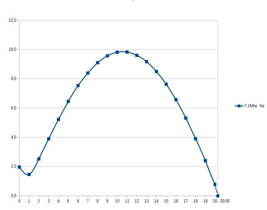
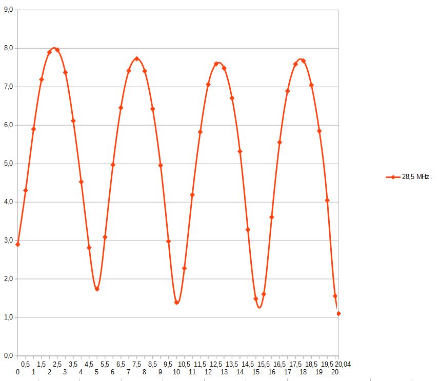
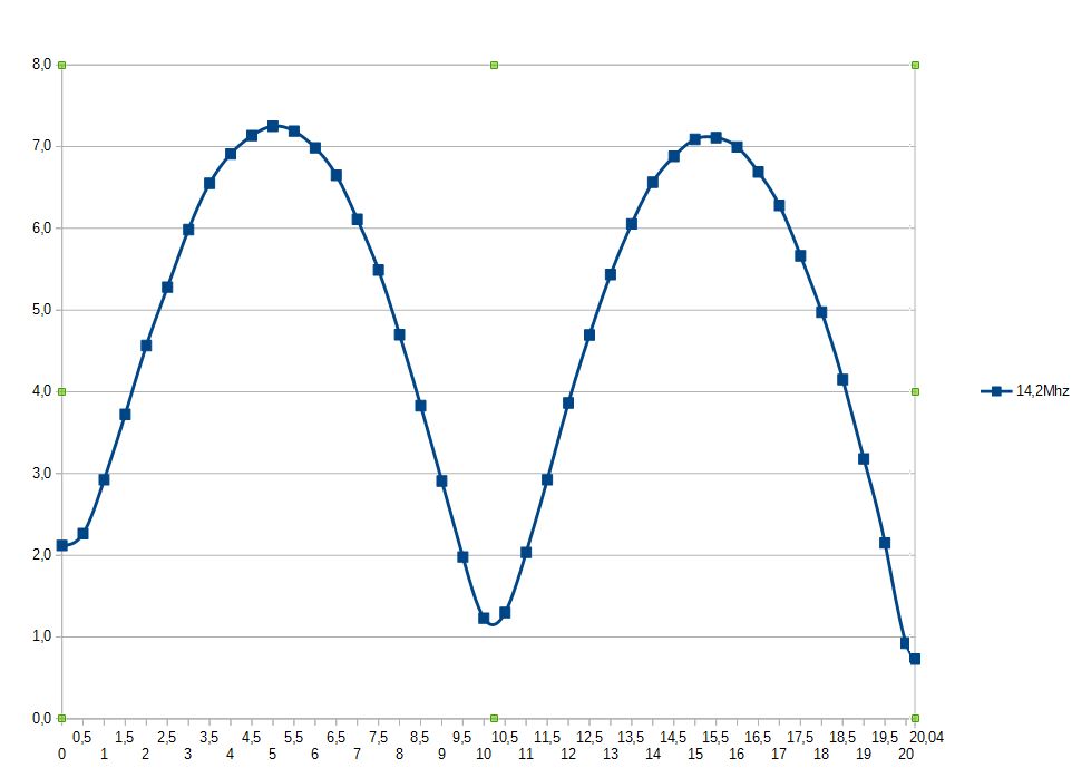
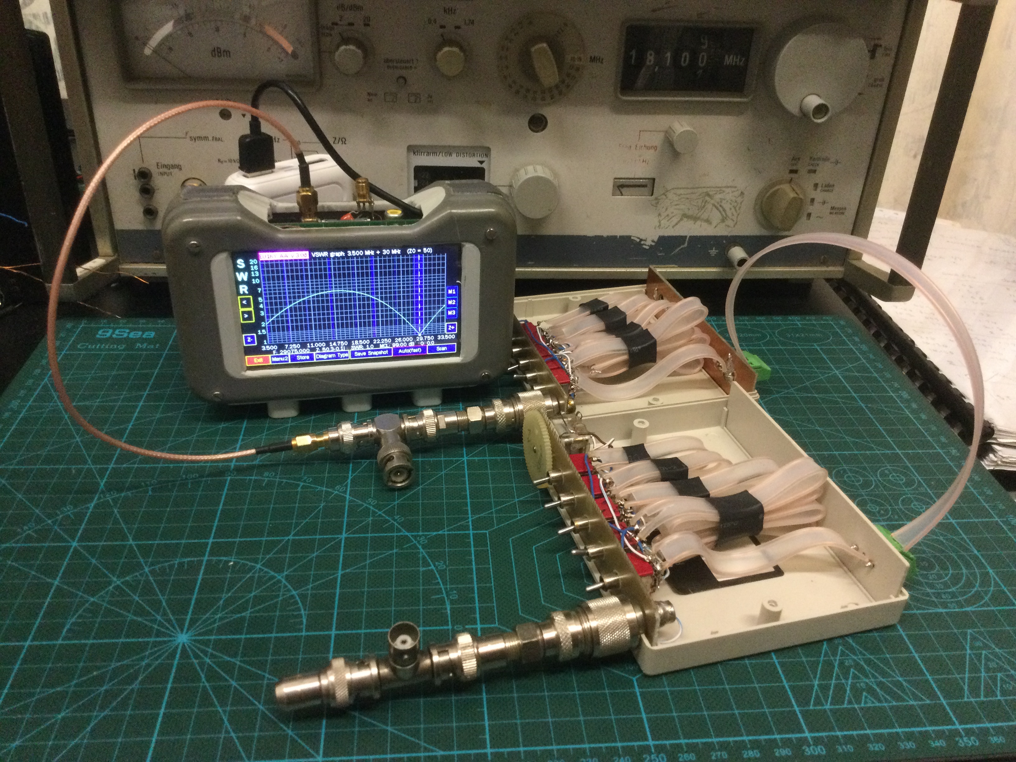
It can be seen that there is no optimal length for the antenna wire, although the frequencies are approximately multiples of 7.1Mhz. I optimize it for the 20m band.
The current should drop to zerro at the end of the antenna. This is only fulfilled at 40m and has not been investigated further.
Very interesting graphs and they make me wonder whether you also measured current in the other side of the feed system, or on the feedline outer conductor.
I assume you used a current transformer to examine the current. Putting such an instrument on the end of the antenna would alter its resonance, I think. Especially if a person is holding the insturment at the same time!
Hi Andrew,
how are you? I use a current transformer, a diode and a very small LED measurement module. Not larger than 4x2x2cm. I hung it on the antenna and read it at a distance of 1m. I couldn’t notice a change, when I go to a greater distance.
73 Chris
There is an excellent article about feedline length for end fed antennas here: Of end-feds and feed-lines
It’s a good read for anyone thinking of using an end fed antenna, with much food for thought. The short version is that feedline lengths of less than 1/4 wavelength shouldn’t have a significant impact on antenna performance. Longer feedlines are only problematic at certain lengths, and careful choke placement can be effective with enough forethought.
The same author also did an excellent experiment regarding current distribution, with results that are very similar to what’s already been shown in this thread. You can find it here: Electrically isolated end-fed vs. center-fed dipole radiation
Very interesting and thanks to all contributors. I have a question:
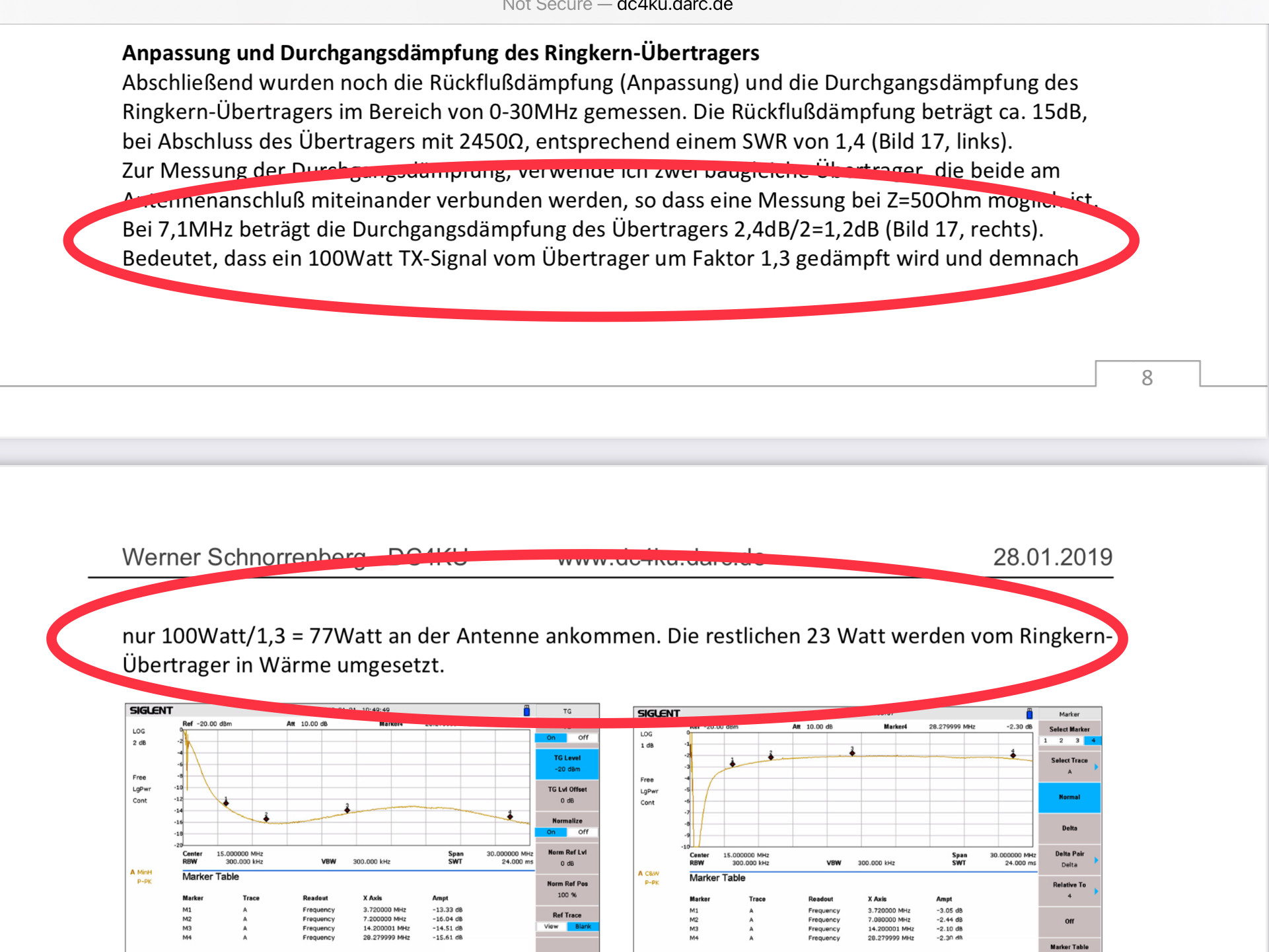
I learn from your reference, a single device (ferrite core and copper wire) has a loss about 1.2dB, meaning 100W in, 23W will dissipate in heating the toroid.
It could be better but 77% is not too bad a price for a simple multi band antenna. A ZS6BKW doublet ATU system might be no better. And it’s an order better than those dinky tapped whips touted as great SOTA antennas.
Hi Pascal,
If you read some of the posts from Heinz in this thread, you’ll see how you easily achieve more than 90% efficiency (e.g. using different toroid geometry and thigh winding with CuL).
Why using a resonant EFHW antenna? Well, it’s super easy to setup and it’s resonant on several bands, just to name two reasons.
Hi Stephan
I was badly expressed, my question was attributed to the HyEndFed device, not the Heinz’s 1:49 device and more than 90% efficiency with ferrite toroid.
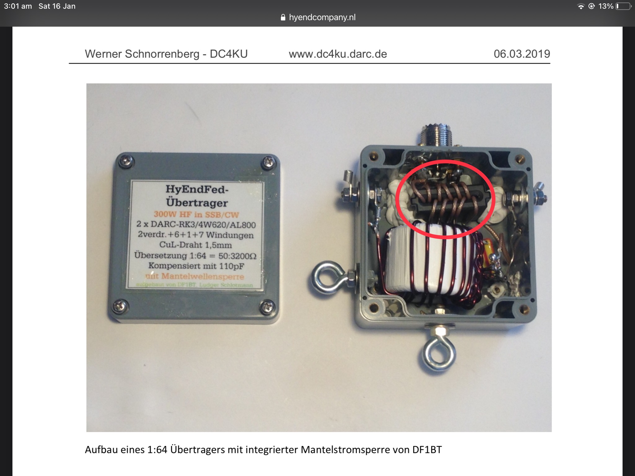
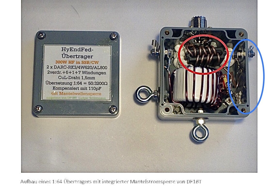
The author mentions about that HyEnddFed device with proof of RF current circulated on pigtail or coax shield. I had a look at the inside picture, there is a coaxial choke (bifilar choke) built in! Wander to know the source of those currents from coaxial shield or pigtail come from?
Hi Ron,
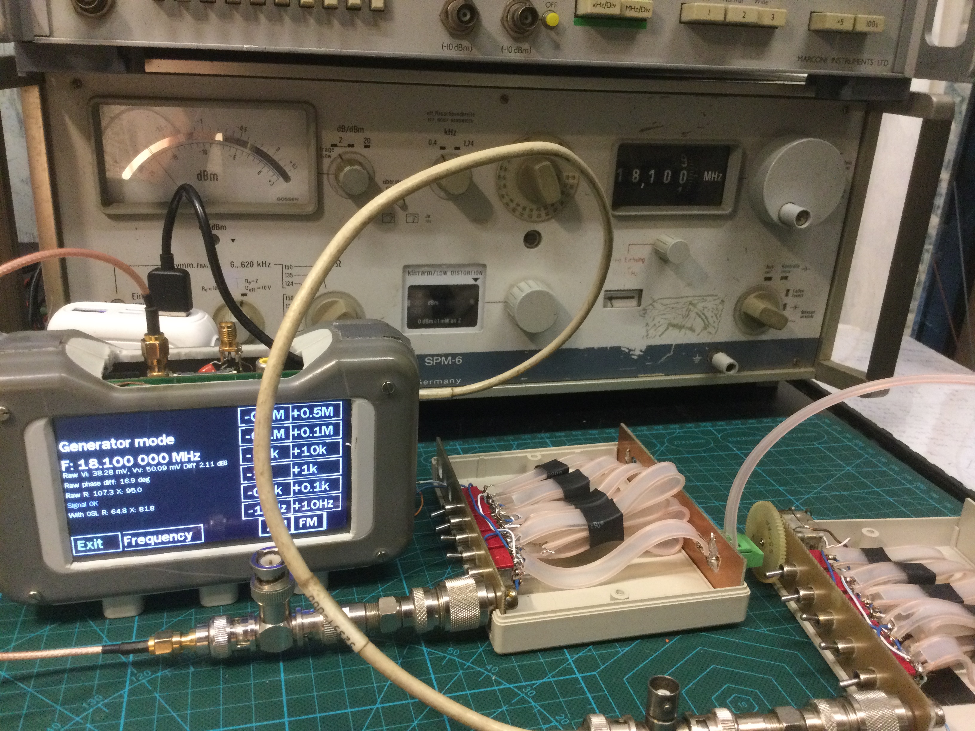
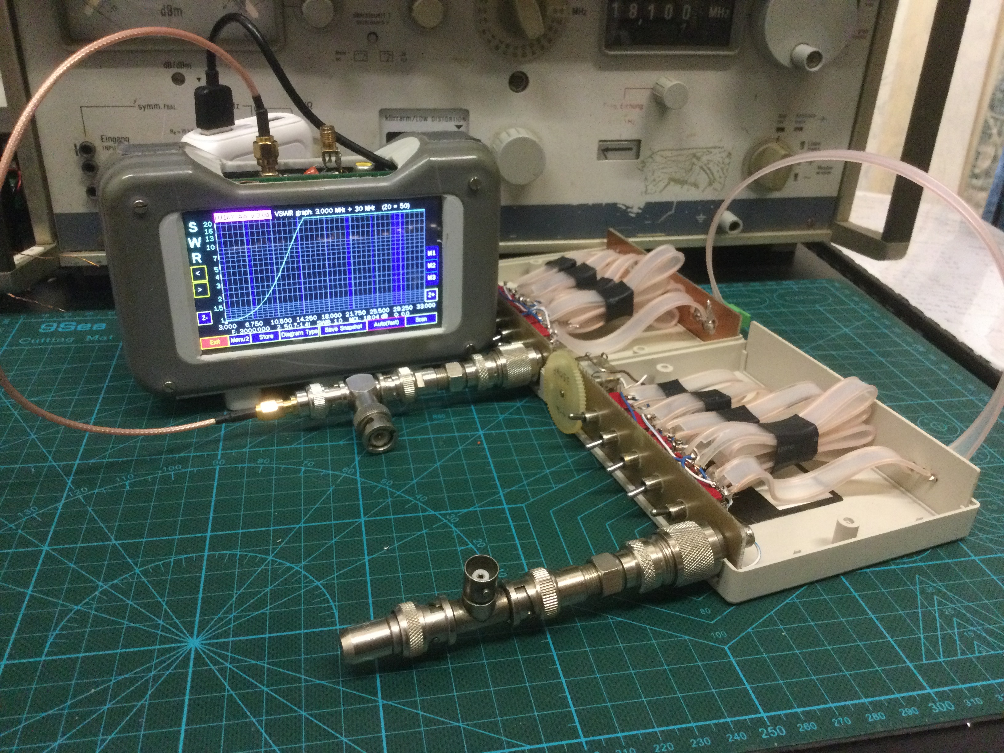
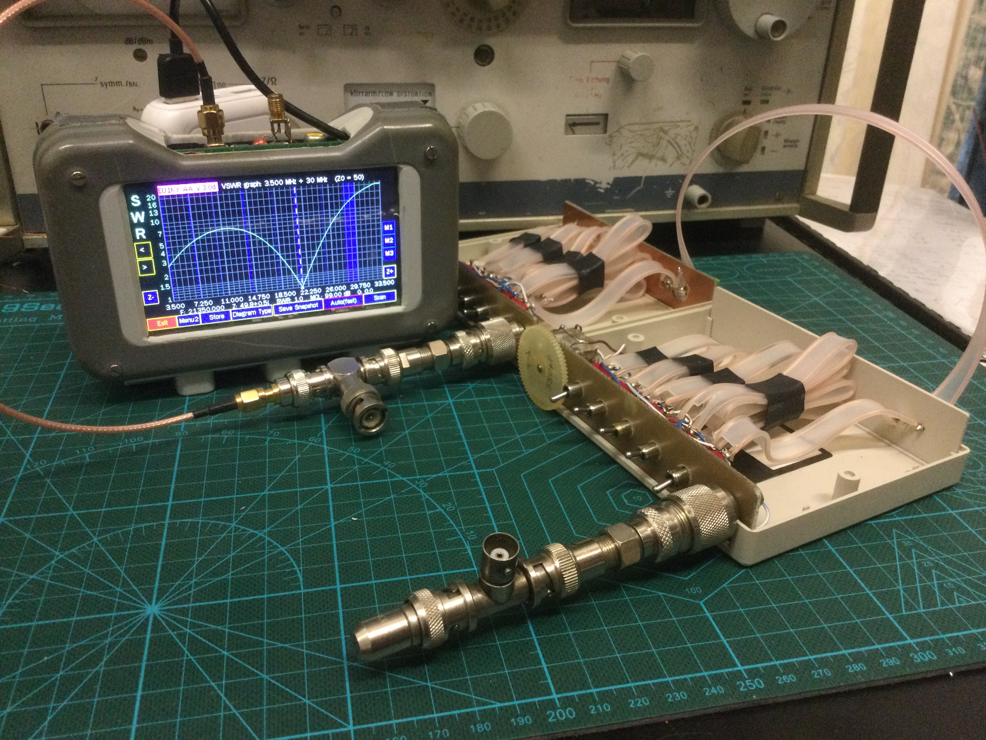
I developed and built a tuner for ZS6BKW by the use of 300 Ω feed line only.
It works on incremental variation of feeder length and a plastic varicap for fine tuning (10, 20, 30, 50cm lengths with 4 DPDT switches).
A back to back test reveals no reflection and less than 0.1 dB loss.
We should be careful not to produce quick shots. The photo does not show a HyEndFed product, but a realization of DF1BT of an EFHW coupler with integrated common mode choke AND as can be read in the text of his contribution, as a completion of the EFHW antenna, a so-called “pigtail or counterpoise” (not shown on the photo) to be connected in front of the common mode choke (marked in blue on the photo below).
Well I constructed three different couplers (transformers) #1 is a 14/2 with a Bifilar primary and a cross-over (similar to those shown in several websites), #2 is the same as #1 except with 21/3 (21 turns secondary and 3 turns primary) and #3 is no crossover, 24 turns secondary and 3 primary with the windings compressed tightly like the photo shown by HB9BCB in his original response.
I did 3 back to back RBN tests of the three different couplers.
They are with 3 different wire sets for the different couplers. The test was done on 80m band within 30 minutes of each other in the evening near 2334 UTC or local time about 8 pm in the evening.
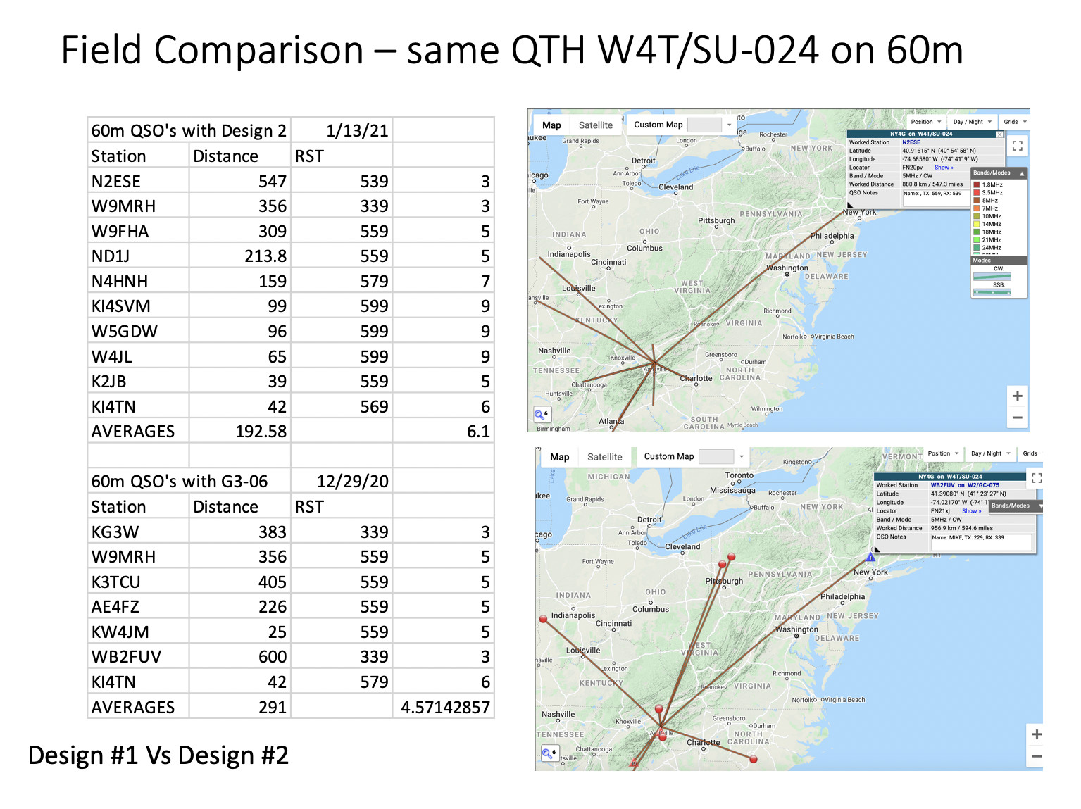
I will go on an activation next Wednesday to obtain a similar comparison from the field. I have already results from the field from #1 (12/29 W4T/SU-024) and #2 (1/13 W4T/SU-024) and now want to get results from #3 (planning on W4T/SU-062 just 20 miles north of W4T/SU-024). I am not sure how objective this is but Design 2 has 1.5 S unit better on the RST compared to #1 and more answering stations on 60m. The comparison has been made using SMP. I also managed a QSO on 80m with #2 (an S2S) but not with #1 on 12/29/20. We will have to see how #3 does in the field.
Such comparisons of RBN spots can actually be misleading if one does not consider the triggers the skimmers use to drop a spot.
If, for example, a station calls cq on the same frequency with the same callsign and the same speed for a certain time, the number of RBN spots will be not the same as if the same station would have changed the frequency or/and the speed by a few kHz or/and wpm several times, e.g. after changing the test object
However, even taking this into account, there is still the possibility that interference occurring at the location of a skimmer could impair or make reception impossible in a certain frequency range for a certain period of time
In order to be able to exclude also any unknown peculiarities of the reporting system, one would probably have to swap the order of the test items in a further test
In addition, if the condx are fluctuating, a test duration of approx. 30 minutes can definitely influence the results.
From this point of view, your above test documentation is unfortunately incomplete and therefore not necessarily meaningful.
But that someone could come up with the idea of making antenna comparisons based on RBN spots that are 2 weeks apart, as in the case of the comparisons made above at 60 m, I have never seen before, really not.
Not really coming to conclusions at this point. Just analyzing data and presenting it. I did change frequency between transmissions from the different couplers. I agree with your assessment. Perhaps a head to head test using WSPR conducted at the same time will be a more objective test.
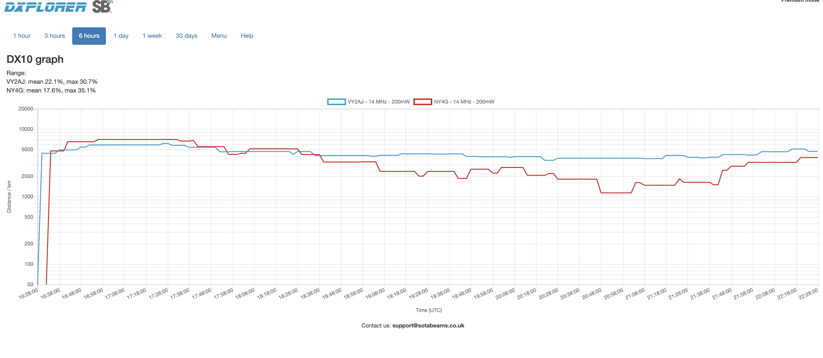
Well I did a head-to-head WSPR test using WSPRlite transmitters using two of my call signs. I used VY2AJ (my Canadian Call Sign) to transmit using the high efficiency core which I called “Design 3” versus the 14/2 secondary/primary using the “conventional” bifilar winding with a crossover which I called “Design 1”. I only have two WSPRLite transmitters. Both antennas are configured the same way - inverted vee with 6 meter apex and the same azimuthal orientation from the feed point to the end of the wire. The transmitters were started within a minute of each other and the test was conducted over a 6 hour period from 11:30 AM local time to 5:30 PM local time to get a variation of propagation for both the transmitter and receive stations. The result is as shown by the DX10 Graph which plots the average of the 10 most distant receiving stations for the previous hour. The red trace is the less efficient core and the blue trace is the more efficient core.
During very good propagation, the less efficient core can hit distant receiving stations just as well as the more efficient core. As the sun sets over Europe, the more efficient core transmitter can still hit distant stations and the less efficient one less so.
DXplorer (software used in analysis of the WSPRLite) has a feature called “simultaneous spots” where the receiving stations report the SNR from the two transmitters received at the same time. This of course changes over time but the SNR from the more efficient core shows a trend for better SNR (signal to noise ratio).