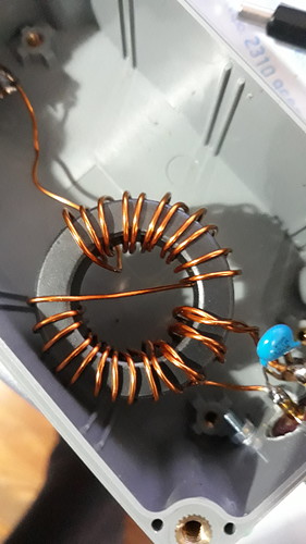
Ok Stephan, my project to improve the EFHW couplers used so far (in the slim design) lasted from spring 2018 to autumn 2019, that was a little longer than expected (…).
For this purpose, after a prior evaluation using the toroidal core calculator from Owen Duffy, prototype couplers 1:49, 1:64, 1:69, 1:81 were built, measured on the workbench on purely resistive loads and back-to-back and finally tested on real EFHW antennas for 80-10 m. The following ferrite cores were considered:
- Amidon 2x FT-82-43, FT-140-43
- Fair-Rite 2643625002, 2643626302, 2643801202 (comparable to FT-114A-43)
During the measurements with the VNA SDR-Kits v3, the values calculated by the toroid calculator have been confirmed quite well, taking into account the large tolerance of the AL value of the ferrite mix.
Core selection
Because at the time I was obsessed with the idea of building the most efficient coupler possible, I chose the smallest Fair-Rite core 2643625002, which seems to be just sufficient for a load of max. 15 W cw/ssb and 10 W data.
Sticking points
Somewhat unexpectedly, some sticking points emerged during construction:
Point 1
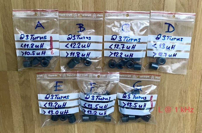
With the 20 toroidal cores from the 1st batch, it was not possible to build 1 pair of 1:49, 1:64 and 1:81 couplers each with almost identical electrical properties.
Reason: The AL value of the #43 ferrite mix varies by approx. 26% with this toroidal core (arithmetic mean of AL(1 kHz) = 1.344 uH/1 turn).
With 20 toroidal cores from a 2nd batch (from another supplier) this goal could just be achieved.
Another batch of 30 cores was then required in order to be able to build some couplers for my SOTA colleagues (…).
Point 2
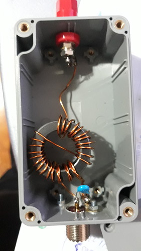
The reasonably accurate reproducibility of a coupler was extremely difficult. This is not only due to the large tolerance of the mentioned AL value, but also to the fact that the coupler is very sensitive to stray capacitance. For example, unevenly spread “primary windings” had a strong effect on the electrical coupler properties.
Therefore, all turns were not only attached tightly, but then pushed together completely. That was almost a watchmaking job, hi.
Point 3
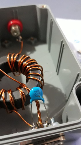
The aforementioned sensitivity to stray capacitance was also noticeable when it was installed in an (adequately small) housing. The stray capacitance due to the proximity to the housing material and, above all, to the material attached to fix the core also tugged a bit on the previously nice-looking graph curves.
Final tests and conclusion
The final tests with EFHW antennas for 80-10 m then only confirmed the well-known: Due to the complex and non-linear permeability of the ferrite material and the non-constant impedance of the EFHW antennas in the range of 80-10 m, which unfortunately do not neutralize each other, result mismatch losses.
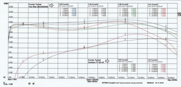
These mismatch losses occur with the following tendency: Below approx. 10 MHz with a decreasing coupling ratio and above approx. 20 MHz with an increasing coupling ratio.
A 1:64 coupler is therefore best suited as a universal coupler for the entire frequency range, a 1:81 coupler for the range of approx. 80-15 m and a 1:49coupler for the range of approx. 30-10 m.
The 1:49 couplers are particularly popular with QRO enthusiasts because of their low transmission loss (-> heating), unimpressed by the high mismatch losses below approx. 10 MHz (…).
As the attached overview with the S21 graphs (of operational couplers) suggests, the project was successfully completed.
Would I choose the same toroidal core again? If at all I would probably use a slightly larger toroid.
73, Heinz
