A mini tuner for EFHW antennas (true half wave)

Background

When I started in SOTA I used for some time different antennas: resonant quarter wave verticals, non resonant random length verticals, dipoles, doublets with tuner, and finally the EFHW (resonant end fed half wave).

The EFHW was the better choice after trying all these different antennas for several reasons:

  • Feeding the antenna at the lower end reduced the required run of coaxial cable when compared to other antennas feed at the centre or high in the appex of the pole.

  • Multibanding the EFHW antenna was easy by placing either manual links or LC traps.

  • It was easy to deploy it inverted V, inverted L, or straight at a lower height in difficult summits.

To connect the EFHW to your rig you need a transformer because this antenna is a high impedance, with a value of around 3000 ohms.

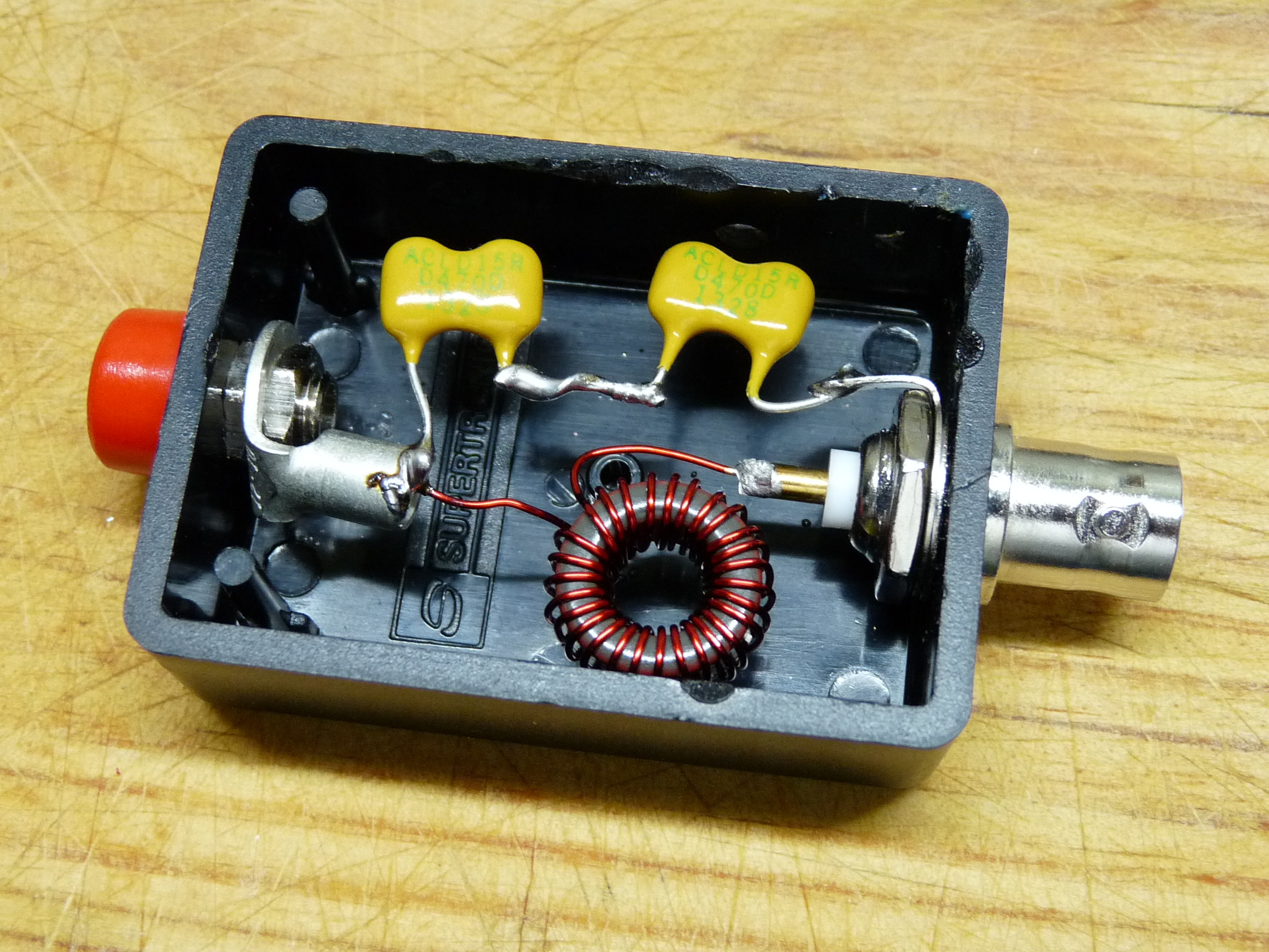
I built an easy to do wideband transformer using a material 43 ferrite ring core. This is a common solution used by many people. The feeder I used is this design, with a FT 114-43:


I have been using this setup for many years with satisfaction. Performance was more or less repeatable but in some summits I experienced troubles with increased SWR level compared to what I had in some other summits. I worked many stations and some DX at the right time, as propagation allowed.

By reading a bit more on the subject, I have seen that this wideband and miraculous transformer has some losses that contribute to be so versatile. These losses reduce SWR and the rig is happy at the expense of losing some radiation.

I have experienced disturbing high values of SWR when QSYing from CW portion of one band to the SSB portion. It makes sense; you trim the antenna wire length to be optimal to either CW or SSB, and therefore, if you go up the band changing frequency, there will be some SWR variation.

For that reason I was motivated to consider a different way of feedind my EFHW.

What could I do to solve my SWR issues and improve performance?

An alternative feeder: the EFHW tuner

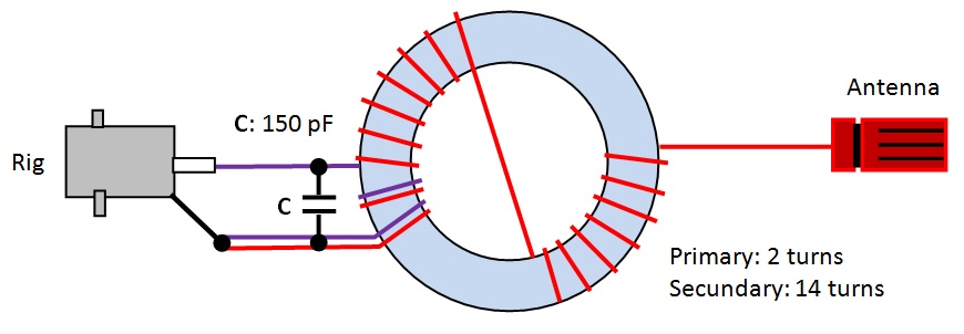
Instead of using the wideband transformer as shown above, I rode about monoband transformers. It is easy to build a feeder using iron powder toroids plus adding a capacitor in parallel to have a LC circuit. The combination of inductance and the capacitor determines the resonant frequency.
FOTO 2

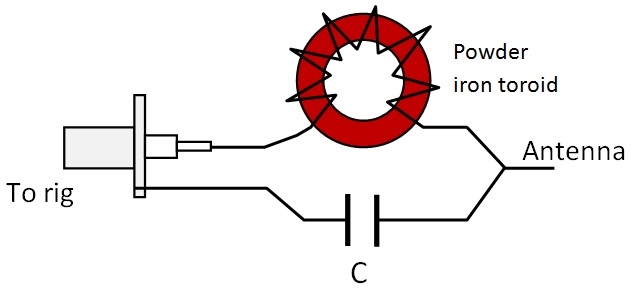
Being my most used bands for a SOTA activation 40 – 30 – 20 meters I decided to build a mini tuner with a variable capacitor that would resonate in all these bands, instead of using a fixed cap that would be valid for a single band.
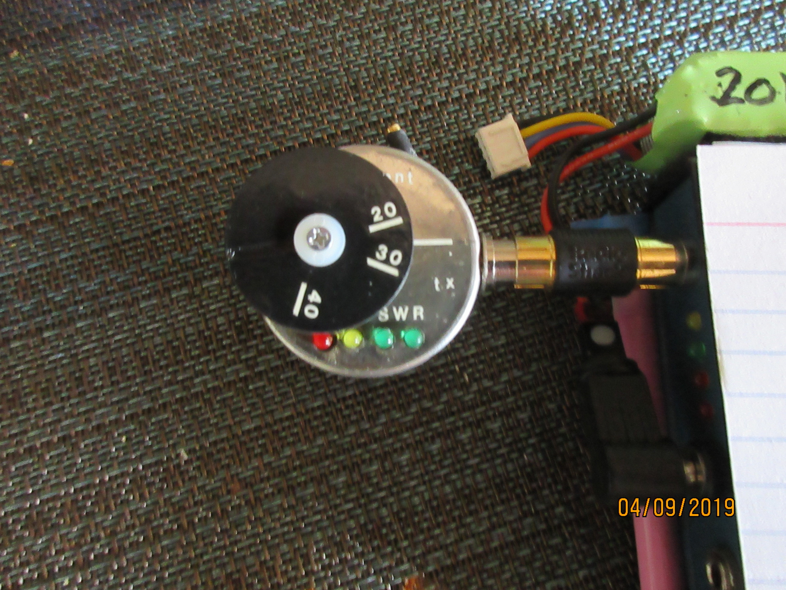
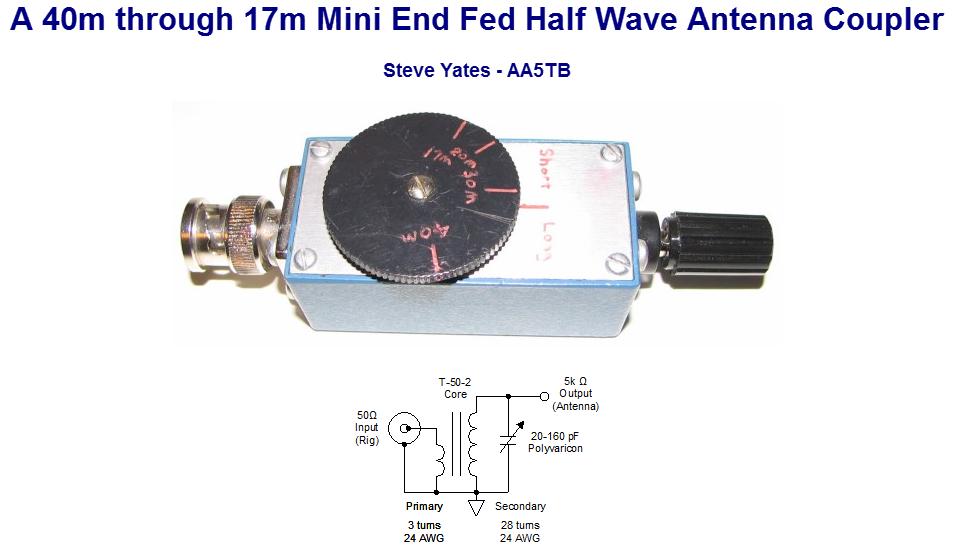
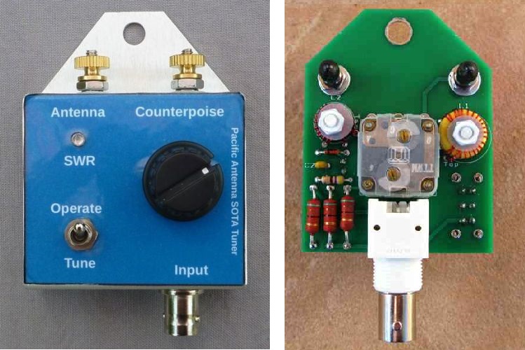
This design is not mine; they are homebrewed designs on internet as well as some parts available in the market, like the Pacific antenna tuner (QRP Kits) or the one made by QRP Guys:

Why should I care to build my own version then?

EA2BD EFHW tuner

Okay, I could buy one of these kits, but I thought I would rather prefer to do my own version with these features:

  • I would use powder iron material 6, which is appropriate for 5 to 30 MHz resonant circuits. Some people use material 2 but it seems to be less appropriate if you intend using higher bands, say between 7 up to 28 MHz.

  • Most tuners have a fixed ratio of 49:1 or 64:1. Instead I would like to add flexibility by making my tuner had the two ratios selectable.

  • Most of the existing tuners use a polyvaricon with a range of about 15 to 250 pF. I would prefer to have the choice of reducing the range of my capacitor for some bands so that the tuning process would be less touchy.

  • I would like a tuner that could work with a max power of 15 watt.

  • I will get rid of putting a SWR led bridge, as I will read SWR level in the rig display.

With these constraints I contacted George, KX0R, one of the best End fed antennas guru. Based upon his experiments on the field he has developed his own versatile tuner, that can handle variable situation and deals with both low or high impedance in the antenna.
His design is here. (opens new window)

My goal was simpler, because I would always use a resonant half wave and therefore the expected impedance would always be high. That would make my design simpler, but I checked with him the doubts I had.
He was very supportive, replied to all my questions and gave me valuable advises on how to assemble my model; thanks a lot George!

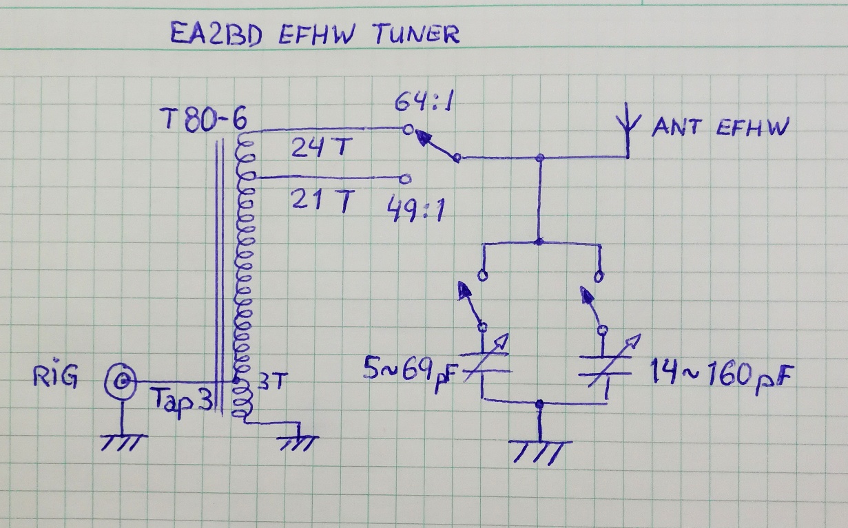
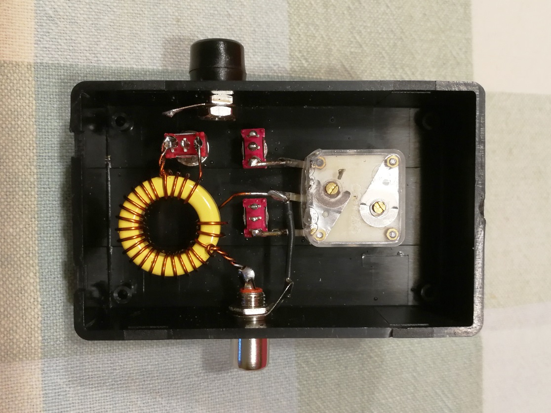
This is how my design looks like:

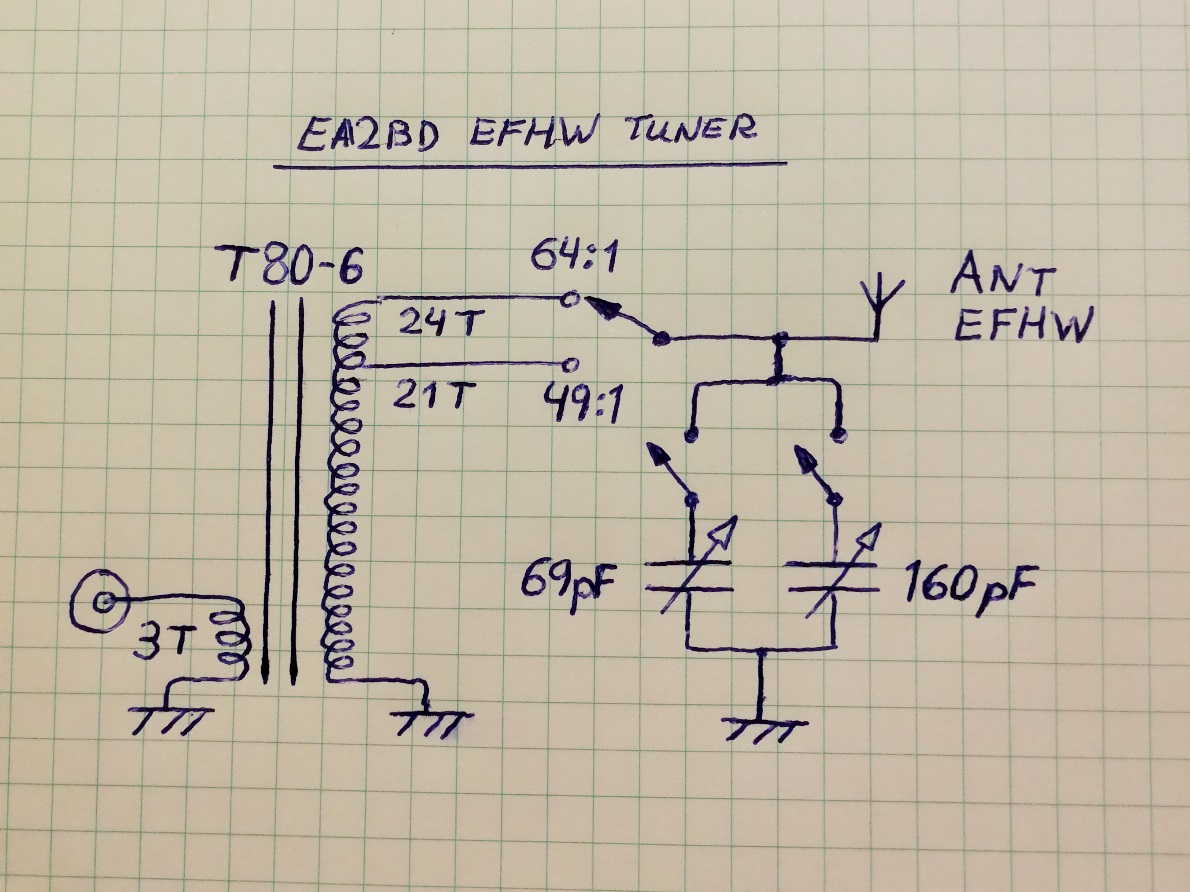
As you can see, I have added two switches in the two gang capacitor and therefore I can select between range 1: 5 - 69 pF, range 2: 14 - 160 pf, or range 3: 19 - 229 pF.

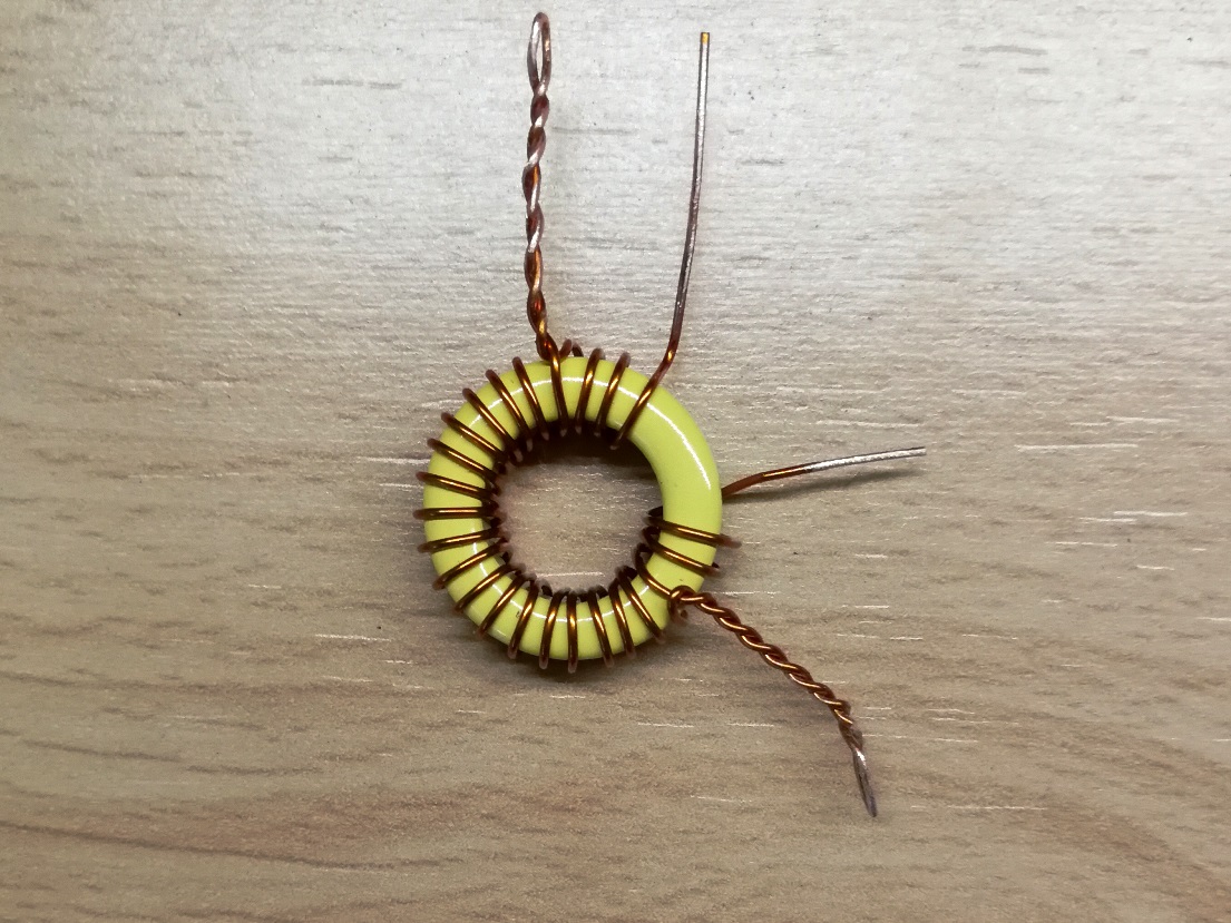
In the other hand, I intend to build the transformer based on material 6 with 3 turns for Primary, then 21 turns Secondary, to have a 49:1 ratio, for a 2450 ohm impedance in the antenna side, and add 3 more turns to reach 24 turns, that is for 64:1 ratio, or 3200 ohm.

Having these two ratios available I can play on the field and have better control of the antenna impedance in its specific location and therefore compensate ground effect variation and its influence on impedance.

It would be great to add some more taps and create other ratios, but this would make the tuning process much more complicated and long. Having these two basic ratios will probably cover most cases. We’ll see later if these ranges are all right.

Building the tuner

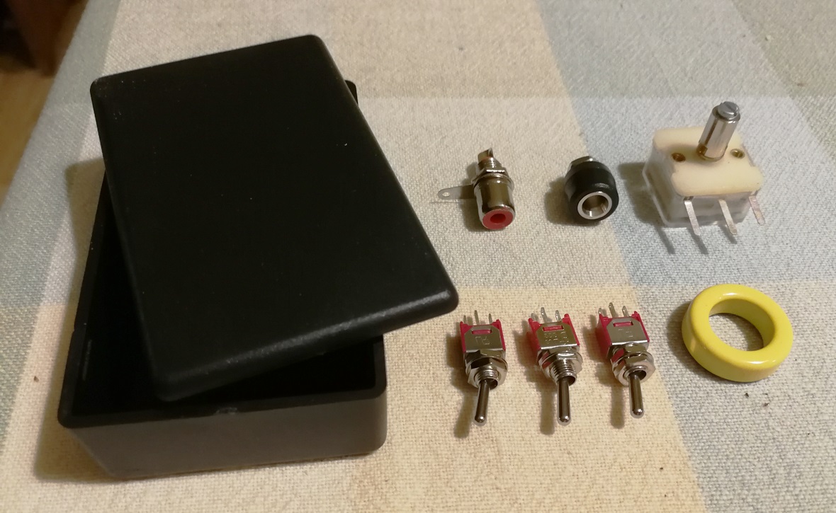
I checked in my junk box and found many of the required components. I just had to buy a small plastic box and aT80-6 core (I choose that diameter to keep the core cool for low power). The rest was available. Let’s see the build up process step by step.

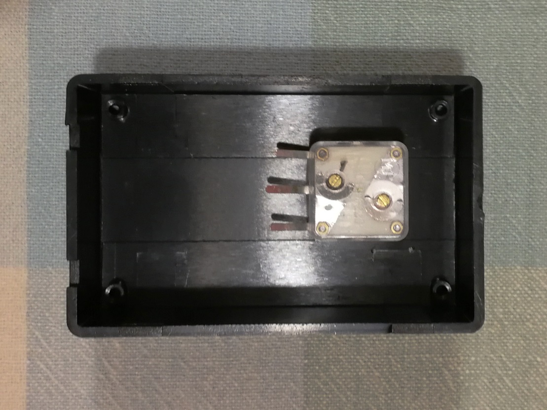
1.) Drill hole for the polyvaricon and fit in the box. Be carefull when tightening the screws onto the body shaft, if the screws go too deep they get inside the capacitor and can deform and damage the inner plates. I added washers to avoid this trouble. Tighten with care.

2.) Drill and install the three switches for the capacitor and the toroid.

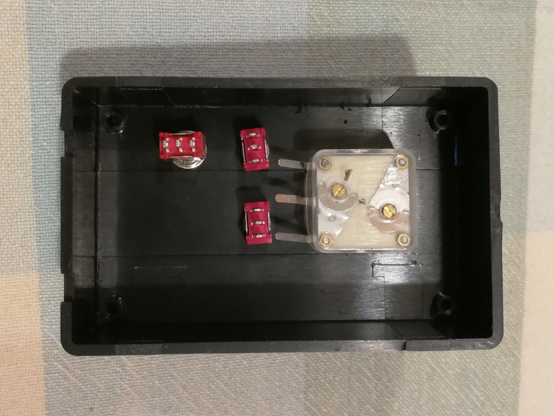
3.) Drill and install the input RCA connector and the outlet banana connector.

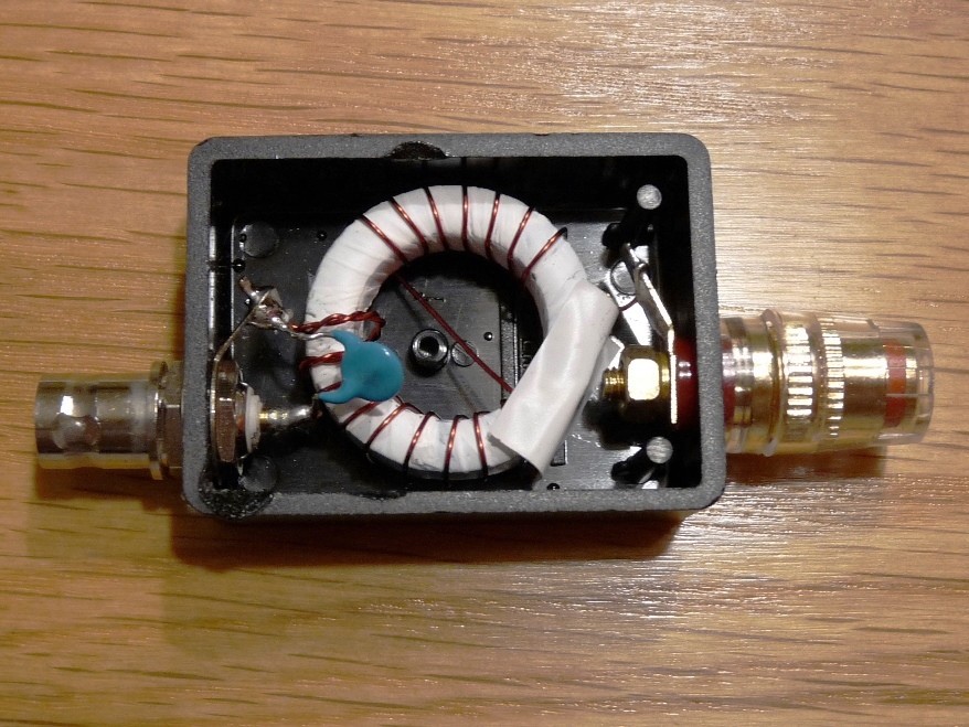
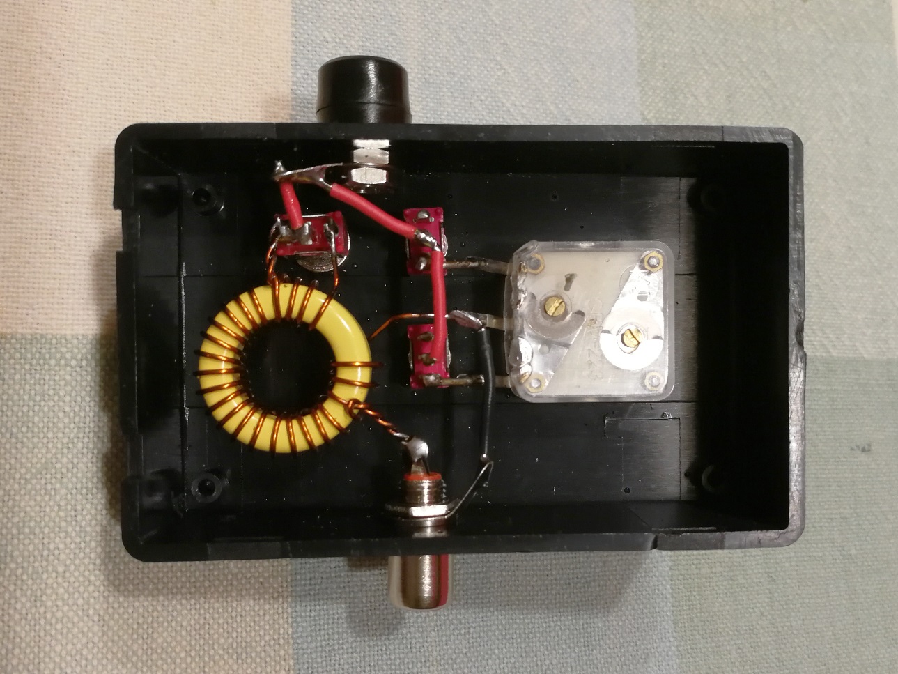
4.) Wind the toroid with 0,6mm ennameled wire (AWG #23), counting each time the wire passes inside the core. Make a tap at nr. 3, another tap at nr. 21 and end after 24 turns. Remove the ennamel in all taps and solder the ends.

5.) Install and solder the core according to scheme. Be quick when soldering to the ground lug of the polyvaricon, avoid excesive heating.

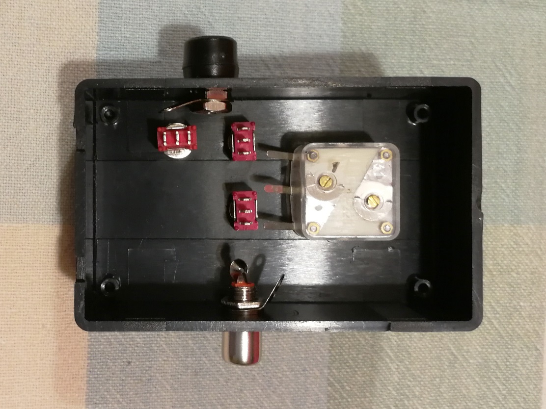
6.) Add wires between the switches and to the antenna connector to finish the assembly.

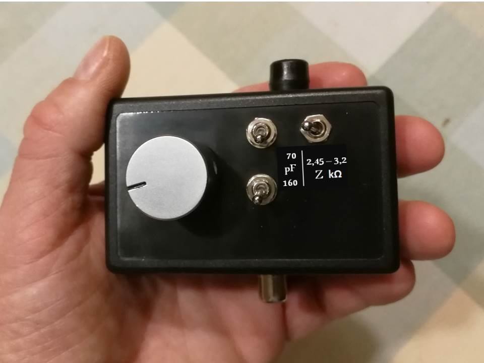
The tiny tuner is ready to test. It weights 58 gram (2,05 oz).

Bench tests

Prior to testing the tuner in a summit I connected a 3000 ohm resistor between the antenna connector and ground to simulate a EFHW antenna.

Then I connected it to the KX3 and reduced power to 1 watt, sent a carrier and rotated the capacitor wheel monitoring the SWR level. I saw a constant reduction of SWR and I soon got a dip at 1,3:1. It worked ok! Being the resistor 3 kohm I couldn’t expect SWR to be just 1:1 because of the existing rates in my tuner, set to 3200 or 2450 ohm. Test agreed with theory.

I compared the different setting of the switches and soon verified that it was a good idea to have a selectable end of range for the capacitor. Tuning process was smooth and precise, and it wasn’t tricky at all.

I checked if it worked in many HF bands and these are the results:
TABLA

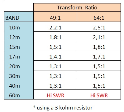
The tuner works best between 40m to 15m, but 12 and 10m are still useable.

It didn’t work on 60m because I would need more capacitance in that band. This could be solved by adding an extra capacitor in parallel.

Concerning the polyvaricon selector, I connect both switches for 40m, just the 160 pF section for 30m and only the 69 pF section for 20m and up.

The tuner works really well and it is easy to tune for low SWR.

Field test

I have perfomed two activation with the tuner and both times it worked equally well.

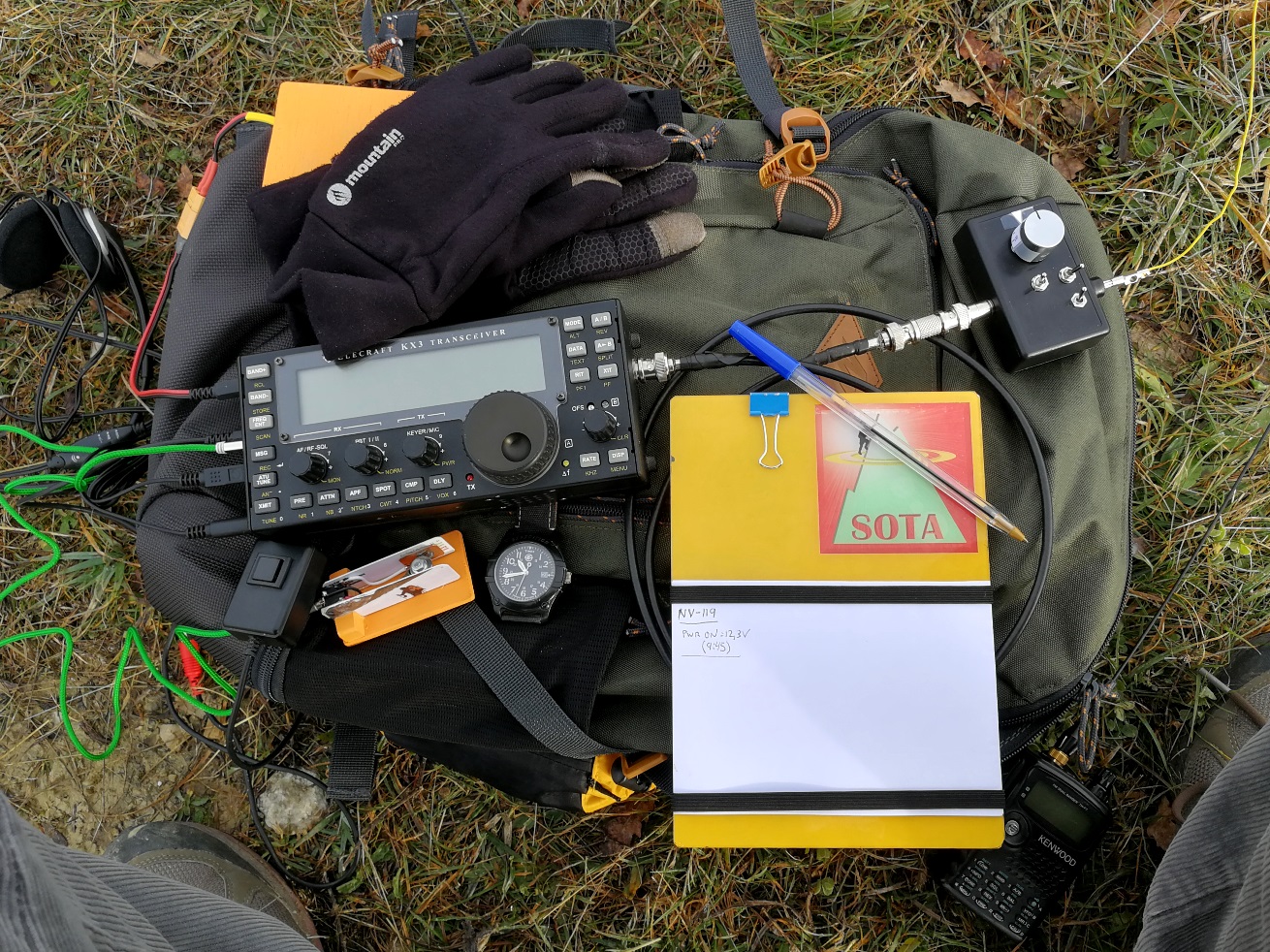
I place the tuner next the rig, over my backpack. In the past I used to put the feeder about 1 meter above ground but this tuner can be placed just over ground. I thought that placing it in the ground would change much more the impedance but so far I don’t see a large influence.

The settings are similar as the ones achieved with the resistor on bench. I normally obtain good values with the 49:1 ratio, but it’s also possible to use the 64:1 and results are similar although the capacitor is set in other position.

The good point in using the tuner is that I can qsy between CW and SSB in the same band and SWR after a retouch of the tuning wheel is perfect for both parts of the band. It takes a few seconds for achieving minimum SWR. A tuner with a single knob is very easy to use!

You can preset the position of the polyvaricon by ear, because turning the knob varies the background noise in the receiver and you can tune until the signals are louder; there you are close to the optimum setting. Then send a carrier and fine tune. Fast and easy.

I will need more activation to check the stability of the tuner but it looks very promising. My last activation ended with 73 qso, good reports, and a DX qso with ZL; things don’t go wrong.

Future development

I would like to measure and compare efficiency of this tuner versus the broadband transformer with material 43.

I don’t have a big laboratory equipment. I could estimate some value by performing Near field power measurements, or power in/power out on bench, I guess…

Is there an easy way to measure efficiency and insertion loss? This would require some study and investigation, but I think it’s not that easy.

In the end, it would probably be a tough work for what I can expect a 1 dB loss.

I guess I get such loss almost with any kind of feeder I use, and probably it’s going to be hardly noticeable by chasers on air to tell which one I’m using.

The real benefit of using my tuner is that it extends my operation protecting the rig and adds more qso in my log.

73 de Ignacio

Pd: if you want to read more about toroid material, check this other interesting thread here.

24 Likes

Your photo does not match the circuit diagram!

You have TWO wires going to the centre of the RCA connector in the photo where the diagram only shows one.

That is because he has wound it as an auto-transformer.
73.
Rod

Hi Colin,
thanks for your interest, right I should draw it in a different way, so here it comes diagram v2.0

Hi Guru,
those 3 wires connect in the antenna banaba post, not to the RCA which is downwards the picture.
RCA only connects to the transformer in Tap nr.3

73 de Ignacio

That is still wrong. An EFHW tuner should keep the hot side of the primary and secondary isolated. It’s best if the grounds are isolated too but that requires you to have a separate counterpoise rather than using the coax braid as the counterpoise.

Take a look at AA5TB - The End Fed Half Wave Antenna

I wrongly interpreted the RCA was the antenna wire connector. Sorry.
I deleted my wrong post to avoid confusing anyone.
73 & HNY

Guru

Nice project, Ignacio.
As is well known, many roads lead to Rome, hi.

However, with a parallel resonance circuit as in the present case, I would for myself put the specified transformation ratios 49:1 and 64:1 in two quotation marks, or better omit this information …

As a general comment on the subject,
it is not surprising that there are actually many myths among HAMs about the suitability of core materials and the efficiency of RF transformers. Unfortunately too much is copied and quoted without knowing what is going on.
And oh dear, what is not all “compared” with each other and understood as generally valid …

Why not take the time to study Owen Duffy’s findings and software tools - and save a lot of bandwidth and storage space on the web, hi.
Using the toroid calculator for rectangular core cross sections one could e.g. easily see the difference in efficiency with only 2 or even better 3 primary turns on a # 43 toroid…

https://owenduffy.net/index.htm
https://owenduffy.net/blog/?s=EFHW
https://owenduffy.net/software/index.htm
https://owenduffy.net/calc/toroid.htm

BTW, There are people who, as they get older, get used to the motto “Sometimes less is more”. My last creation (below) seems to be going a bit in that direction, hi.

73 HNY, Heinz

4 Likes

Hi dr Heinz,
hope you and yours are all fine. Yes, many roads lead to Rome and I’m glad to meet you on the way.

You’re right; I must be careful with the transformation ratios in that core, there are variants I don’t know and I can’t be certain on what the ratios are.
I would love to have much more skills on this subject, the misterious world of cores and transformers. I would like to get in deep details but:
I miss much more time to deal and experiment with that, and
I lack from a well equipped laboratory.

Perhaps something I can keep in mind for when I retire… far away, I’m afraid.
In the mean time I’ll try to read the interesting links you’ve sent and promise to share the advances and new experiments I can do…

Take care and all the best for 2021
73 de Ignacio

Ps: by the way, I also did such monoband feeder, but mine is with fixed capacitors…

1 Like

Ignacio,

The (grounded) parallel resonant circuit you use to adapt end-fed half-wave antennas is called “Fuchskreis” in German-speaking countries because the Austrian Josef Fuchs applied for a patent in 1927 for this circuit.

Note
The grounded parallel resonant circuit is a modification of the non-grounded Fuchs circuit. Since in QRP applications with only a short or no feeder cable, no undesired radiation can arise, this simplified version has become “common” in the QRP community.

Fuchskreis couplers were built in many different versions. The most well-known variant among QRP enthusiasts is the “Multiband-Fuchskreis” for the frequency range of 3 octaves from QRPproject (only as a kit):

1 Like

Obrigado Inacio por compartir este projecto.

Um Bom Año

The Fuchskreis tuners are very different from the simple tuner shown in this article. Unfortunately I have never used a Fuchskreis, yet I know they are popular, and other people say they work well, so there is little I can offer, except the obvious facts visible in the drawings:

In the Fuchskreis circuit from the QRP Project, the low-Z end of the output tuned circuit is not connected to ground, or much of anything else. We see only stray capacitance to deal with the return current from the antenna circuit, on the bottom side of the resonant circuit. The capacitance between windings L1 and L2 are what we see in the circuit.

When I first saw this circuit, I thought this was - or is - a mistake. Surely the lower ends of L1 and L2 should be connected to together and to “ground”, the outside of the BNC input connector. If the lower side of the 200 pF variable capacitor is actually mounted to a grounded metal enclosure, that solves the problem - but the circuit does not show this. If I built this circuit, I would try it with the ground connected across, because I think it will work better, and more predictably, even if it can create a match without the connection.

The operation of the basic tuner built here by EA2BD is simple and uncomplicated. It does a lot of good work with very few parts. It also is easy to use. By adding more switches and more taps on the inductors, a wider range of frequencies and impedances can be created. There is nothing mysterious about it. The transformer can be an auto-transformer as EA2BD has shown, or the input can be a separate primary winding, with the lower end to ground. This primary winding can have taps, as well as a series capacitor. These features allow variable coupling, and a way to get perfect matches for a larger range of impedances. The design is flexible, and you can make what you want from it.

We should not closely relate the Fuchskreis tuners with this simple kind of tuner. If the lower ends of L1 and L2 in the Fuchskreis tuner are really connected together and to “ground”, then the resulting tuner IS very similar to the EA2BD tuner and to the related KX0R tuner.

Until I actually build and test a Fuchskreis tuner myself, I offer no opinion. The circuit is interesting, yet I cannot see why it should work efficiently as drawn. That it will cover a wide frequency range is not in doubt. Using two separated inductors, with just one driven, is clever. Perhaps someone who has thought about this obvious problem of the ungrounded, unconnected secondary of the tuned circuit will explain the answer to us. The only answer I can see is that the transformer L1:L2 somehow couples the energy across to the “ground” side of L1. Does it do this by magnetic coupling, or by stray capacitance between the windings?

This should be another thread on the Reflector, if some of you who really understand the Fuchskreis can help discuss and explain this circuit. If it really works as drawn, there must be an explanation that we can understand.

I use the QRP Project Fuchskreis Tuner extensively and can report that it always works well for me. I made a series of videos on how to build it:

I had always assumed that the explanation for why it works, despite not being grounded, lies with the stray capacitance in the circuit. However, it would be interesting if someone could give a fuller explanation. The only issues I’ve ever had with the circuit have been on 80m.

  • As supplied, there is only just enough coupling on 80m. I could never get below 1:6 without lengthening the wire by a few meters. My videos detail how and where to add more windings in order to improve this.
  • The tune on 80m is still very sensitive to nearby objects. Wire fences under the antenna; the wire touching trees and the ends of the antenna close to the ground, all have an effect on SWR. On 80m, the antenna likes to be out in the open.
  • With a long feeder, my QCX 80m was troubled by stray rf. Perhaps the coax became the counterpoise. Whatever the reason, the QCX needed a ferrite choke to work properly. I have not had this problem with any other rigs, and I think it is possibly just the QCX that is very sensitive to stray rf.

Apart from that, the Fuchskreis has worked very well for me, I would recommend it to anyone. Of course, it’s always nice when someone can post a few tips and mods that help improve on these things :wink:.
73 de OE6FEG
Matt

ARRL members can read the findings of Josef Fuchs in the copyrighted post:
QST, July 1928, p. 37 and 42 (continued), Tests on a Method of Voltage Feeding the Antenna.

BTW, A bit strange, there is NO criticism to read in this thread of the well-known basic circuit used by Ignacio EA2BD. This grounded parallel resonant circuit is already described in old antenna books and can be found in many, also particularly clever, implementation variants (self-made, commercial).

So why such a detailed justification anyway? Is it because there is no explicit praise for this circuit? Sorry, I really don’t know and therefore don’t see any need for it.

Edit 02.01.2021
That’s another example of a nice-looking, ingenious implementation variant of an ATU based on a grounded parallel resonant circuit.

Surprisingly easy for non-members to locate as well.

1 Like

Hello,
thanks all for your contributions.

I think we all are aware that when someone publish any idea about antennas there is going to be a bunch if opinions and debate.
I don’t intend that my system is better than others. There are many different ways to feed an antenna and make it work.
Every solution will have their pros and cons.

This is an amateur world, and as for such, it is great that we contribute together to share our experiments so that we spread knowledge, because we just know part of the truth of this very complex subject of antennas.
There are lots of articles and, by misfortune, a lot of contradictions between some sources. If we could just have a good compendium and comprehensive source of the whole subject!

My very basic tuner is working for its purpose, tuning EFHW cut to true half wave lengths and make them work when changing frequency between CW and SSB portion. I just introduced some minor features that I have not seen elsewhere in this design. That’s it.

Hope it can help to solve any other’s trouble as I had, but you can choose whatever other existing alternative…

73 de Ignacio

4 Likes

Very nice tuner, Guru, (and tnx mni chases). To respond to some of your questions/statements:

Loss with the broadband matching device, I made several of them over the years, and using T37-43, T50-43, and T80-43 cores for use with 5 watts. I tested them for loss by putting them back to back and running five watts into them. The T37 lost almost two watts out of five. The T50 lost only 1.25 watts out of five, and the T80 lost only just over a watt. This is with a close match. Losses rise rapidly when the SWR rises. I have found deployment on some peaks caused significant change to resonance perhaps because of ground conductivity, perhaps because of variations in vegetation, who knows.

The back-to-back test using two of the AA5TB type of mini-tuners was also done. In this case the loss was only 3/4 of a watt out of five. Using this with an EFHW I have always been able to get very good match in the field (using the same antenna deployed with the same pole and in the same way). I have not encountered the need for the wider variations your switches are designed to handle. I use just the smaller of the two sections in the capacitor, and adjust the trimmer so as to be able to just reach 40M.

CU from/on a peak and have fun making stuff!

73 Fred KT5X ( aka WS0TA )

small AA5TB type tuner with tinySWR indicator by DK3IT used without any feedline:

4 Likes

Fred,

Is your reference to this coupler?

A 40m through 17m Mini End Fed Half Wave Antenna Coupler

Steve Yates - AA5TB

Hi Fred,
thanks for your testing results, that’s what I’m interested to know…

Yes, most conventional tuner deal with that with a single set of polyvaricon. I see that less than 60 pF must be used for 14 MHz and up, less than 160 pF is required for 10 MHz and less than 270 pF for 7 MHz. All this could be accomplised with a single capacitor of 270 pF end of scale, but tuning is smooth if the scale is adapted accordingly to a closer end of scale, so that little variations of the wheel don’t change the capacitance by a large amount, especially in higher frequencies.
That’s just a little aid to tune, but you can proceed with a single scale as you do with yours.

Fred, it would be interesting to know wich core you use there (T50-6, perhaps?), the winding descrption and the capacitor type… Could you provide any detail?

73 de Ignacio

1 Like

yes.

fred

Thank you Fred, then this is yours:

I see the windings are a bit different compared to mine, 3 / 28 turns, curious to see a theoretical “9,3” ratio (for a 4325 ohm load).

Anyway, as long as it works thats fine!
73 de Ignacio