A mini tuner for EFHW antennas (true half wave)

Ignacio,

If in a previous post I recommended that you omit the designations 64:1 and 49:1 in your diagram, I was afraid that you might not fully understand the function of the circuit used. That actually seems to be the case now.

No problem, just consider the primary winding as a coupling loop for the tuned parallel resonant circuit, formed by the secondary winding and the variable capacitor. What is required here is the well-known Thomson oscillation equation, ok.
BTW, to achieve maximum efficiency with a multi-band coupler, both the degree of coupling (number of primary turns) and the parallel resonant circuit (capacitance AND inductance) would have to be variable, because both are frequency-dependent.
Note: Due to the load of a connected EFHW antenna, the parallel resonant circuit is of course slightly detuned, but can easily be brought into resonance with the variable capacitor.

BTW, Doug DeMaw W1FB did a pretty good job of illustrating his explanation of the subject, didn’t he?
QST April 1985, Resonance and Tuning Methods

Hello Heinz,

you see? I’m still far away and need to study a lot more.
Thanks a lot for your information and the attached file. It helps a lot to understand what is going on with this coupler.

73 de Ignacio

EFHW tuner v.2 (grounded parallel resonant circuit)

I have been happy using the EFHW tuner described at the top of this thread (v.1) since December 2020.

Tuning the EFHW antenna after any band change, or when moving from SSB to CW section in a band was fast and easy. The tuner has served me well but SWR was best only between 40 to 15 meters.

Due to the current good solar conditions, I wanted to find and improved version to use higher bands to cover up to 28 MHz.

In the other hand I wanted to add a SWR led indicator to aid in the tuning process. I have a few little rigs without an SWR readout on the display and a led would help tuning the capacitor while the tuner is far from the rig, hanging at the antenna feed point.

The heart of this tuner is similar to the one in v.1 shown at the top of this thread, but I added two slight changes: a variation in the windings and a led SWR circuit.

The inductance is again an autotransformer. The Primary is selectable between 2 or 3 turns so that I choose the best in case I need it.

The Secondary has also a two position switch to select between a tap after 12 turns (including the Primary ones) or the end of the winding at 16 turns.

I measured the inductance values of the toroid:

Primary:

  • 2T = 0,05 uH

  • 3T = 0,13 uH

Secondary (measured after the tap at the end of the Primary):

  • 12T (9T after Prim) = 1,10 uH

  • 16T (13T after Prim) = 1,83 uH

The polyvaricon is the same than for the v.1, with two set of plates in parallel. Its range was also measured:

  • C-Lo: 4 – 64 pF
  • C-Hi: 16 – 163 pF (Max value both connected is 227 pF)

Concerning the Led SWR indicator, I bought a cheap kit in Kanga products (SWR-1 resistive bridge), a clever implementation of Wheatstone bridge circuit that was easy to solder on a neat mini PCB, including three 51 ohm 2 watt resistors, a switch, a trimmer (to adapt the led sensitivity), a 1N5711 diode, a 1K resistor, two 0,01 uF caps and the Led.

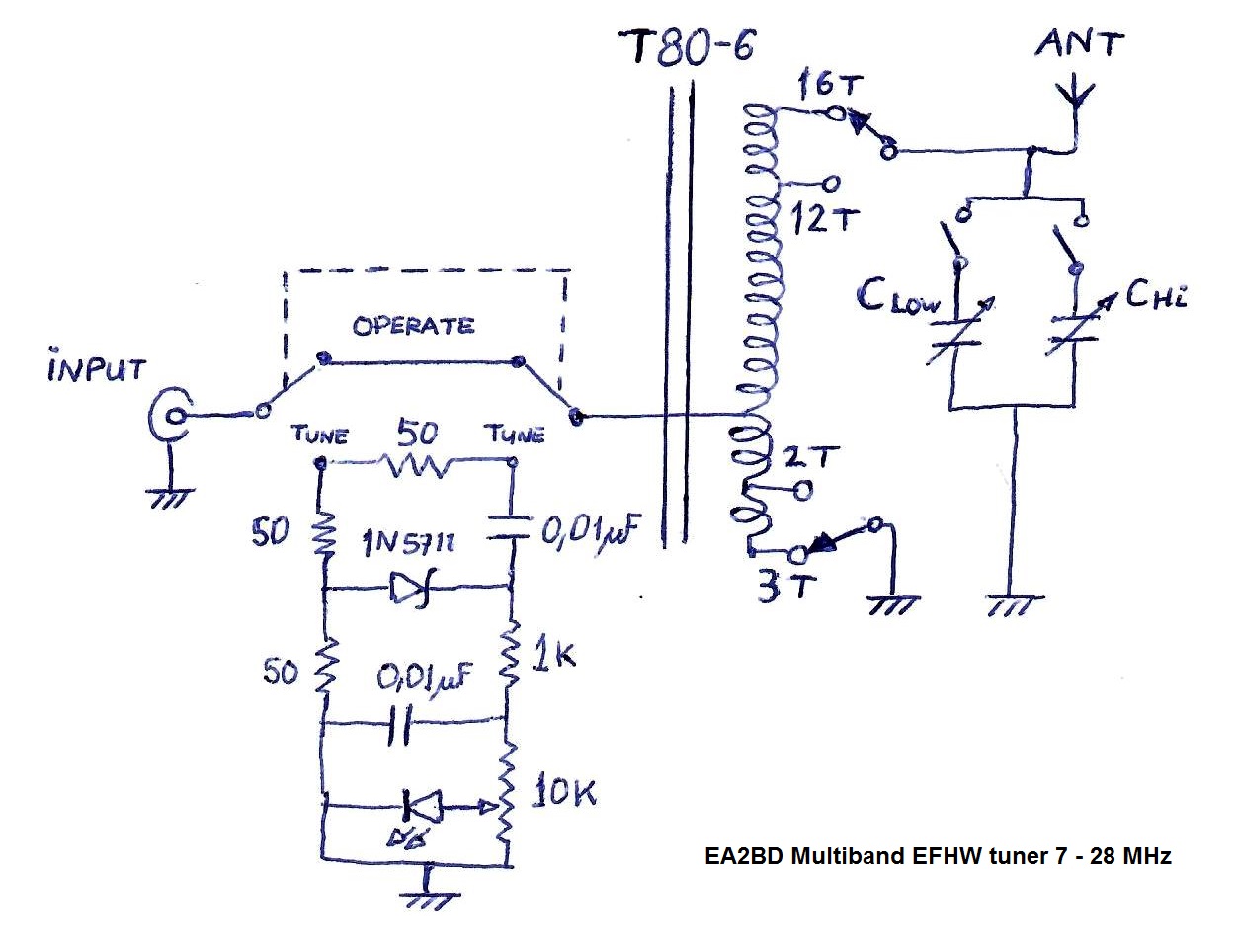
The schematic of the complete tuner is here:

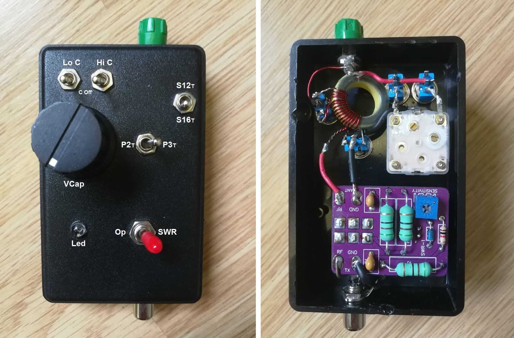
And this is the final assembled tuner:

v.2 Tests

I tested the function by connecting a 3K ohm resistor at the outlet plug and the SWR values were very good.

Using a 20 m long wire I can tune it in 14 – 21 and 28 MHz with good levels of around 1,2:1.

In the other hand, I had difficulties to tune in 7 MHz as the min SWR achieved was 2,5:1. It seems I’ll still be using the v.1 tuner for the lower bands.

I have prepared a monoband EFHW for 28 MHz (about 5 meter long) and the v2 tuner worked just perfect. I got very good results, logging lots of transatlantic contacts this way and I even participated in the ARRL DX CW contest running portable QRP, just for fun.

73 de Ignacio

10 Likes

I’ve been using the QRP Guys EFHW Mini-Tuner for a year or so an am very happy with it. It’s very similar to your design, but it’s impedance ratio is about 60:1 and it only has one tuning capacitor, which means a tiny rotation can make a large difference in SWR. It’s quite usable if I have a steady hand. An EFHW antenna with a variable capacitor across the secondary is sometimes called a Fuchs antenna, which was named for the author of a paper or patent on it.

I appreciate having the built in LED bridge tuner. If it dims even slightly I know it’s below 2:1, and if it turns off completely it’s more like 1.2:1. I’ve confirmed this many times with a NanoVNA, so I no longer need to check the actual SWR. But if you have an SWR meter in your transceiver, I agree you don’t need it.

After testing my mini-Tuner with single-band wires for the 20, 30 and 40m bands, I decided to make a trapped tri-band antenna to cover all three. I used the QRP Guys trap kit, which included all materials to make four traps at a very reasonable price. I only needed two traps, but it’s good to have spares in case I want to make another antenna. The build was easy, but tuning the two traps and adjusting the segment lengths was a bit tricky. A NanoVNA was a great help. If you watch a Smith Chart as you rotate the capacitor you can quickly get an idea of what adjustments need to be made to bring it in better tune.

I considered adding a potentiometer to adjust the LED sensitivity. That would make it easier to see the LED dim in bright light. But that has the disadvantage that I’d no longer be sure if the SWR was below 2:1. With the potentiometer I would only know that the capacitor had minimized the SWR but will tell me nothing about the actual SWR value. Since my transceiver has no SWR meter I prefer having the LED sensitivity fixed.

1 Like

If you measure the RF current (with a current transformer and meter on the wire), then as long as the antenna is exactly the same, you have a true measure of the (relative) power when you compare two matching units.
(Field strength in the near field will tell you the same, but again, only for a constant antenna.)
Radios with built in wire tuners like Codans and marine sets commonly had an RF current meter or light to tune them with. It is both simpler and more valid than an SWR indicator

1 Like

If you connect your capacitors across the whole coil, and switch the antenna off the taps, then your capacitors will have more effect at the low end where you are selecting the lower turns ratio (i.e. you will be able to tune to a lower frequency)

The first drawback of the resonant tuner is retuning at every band change, I built one using a 6p2t switch. Each band selected a transformer tap, and a separate trimmer capacitor. There was another trimmer cap (“fine trim”) with knob across the whole set.
You preset the trimmers for all the bands with the fine trim centred. Then you can just switch bands without retuning. A bit of fine trim adjusts for how the antenna is setup on the day.
Personally, I have stayed with a simple broadband transformer because it is at the end of the wire and often out in the rain overnight. It also works with more power when I have the '891

It is also good to understand that a multiband EFHW can only be “resonant” i.e. R=??? X=0 on one band**. On the other bands it presents a complex Z with lots of X and R has only a passing resemblance to 3k.
This sort of resonant match is a much better fit to a multiband EFHW where it can actually match and tune out the reactances on each band, than trying to use a single broadband transformer.

**and not even on one band as you set the length to be good enough on all bands,

1 Like

I have almost the same match unit I use with my 40/30/20 trapped EFHW. It has switchable input and output taps and a 196pF polyvaricon capacitor. Most of the time it’s used with radios with SWR indication built in but I built the same SWR kit for use with my QCX radios. I don’t like LEDs for use in daylight and so I bought a moving coil meter from eBay. Adjust for minimum deflection. The nice thing about that SWR meter kit is the 6dB pad that gets inserted when you switch to tune to help your PA when the match is poor during tuning.

It matches on 40/30/20 with ease, well it should! It matches on 15/12 &10 but cannot match on 17m unless link in the antenna is pulled at the 17m HW position. The match on 15/12/10 is normally better with the link open. The unit provides 1:87, 1:64, 1:49 and 1:36 step up ratios

It’s a massive drawback having to spend nearly 10secs tweaking the control to get a match.

2 Likes