Thank you Heinz for your input. I realise you often feel the need to clarify certain aspects of antenna design. I hope you see, I am by no means a self proclaimed ‘End-fed expert’, far from it: I rely on input from people like yourself in order to improve my designs. As to the exact amount of RG178 I use, it should be pointed out that I no longer use an antenna tuned for 40/20, but shortened it last year so that it is tuned for 30/15. That uses about 4m of RG178 (I use 178 for the whole of the antenna + balun), then about 2.5m of double shielded RG174 for the feeder. I will post the Z plot as soon as I get back to Austria and await with great interest any comments that others may have. Gav: for what it’s worth, I think you’re right, the losses are very high on some bands with the 40/20 version. The original End Connected Windom has a 4:1 balun at the feedpoint and this, obviously, reduces the losses induced in the coax.
73 Matt
Matt would you post a pencil diagram of how you wound the two toroids? I have paused all your videos at the point where you show the toroids but I can’t quite make out the winding pattern. Thanks,
Scott
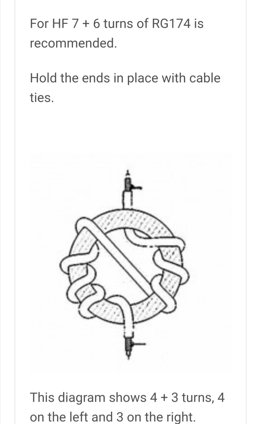
Sorry to be a bit slow getting back to you Scott. I found a good diagram of how to wind the baluns on the SOTABEAMS website:
You won’t need as many turns as I had been using, so try using just one toroid. I am currently tweaking the antenna design to reduce the amount of coax used on the 30m version, and changing to RG316 instead of RG178. I am also designing a 4:1 Ruthroff transformer for the 60m version.
             73 de OE6FEG
                    Matt
Great series of videos about your antenna.
I got on top of the 80m tune part of my antenna by going high in the band where the rig would tune it and Spot myself there and use same frequency for CW and SSB. No interference issues to other modes as my SOTA activities are during the day when I needed 80m.
Regards
Ian vk5cz …
I have decided to rework the smaller version as per your suggestion of using just 1 ferrite and a twisted pair. Because shedding one of the ferrites saves weight, I can use a slightly less lossy coax for the short leg; I will need just 2.75m of RG316. Putting this into the line loss calculator using your measurements for the 13.72m OCFD gives the following results:
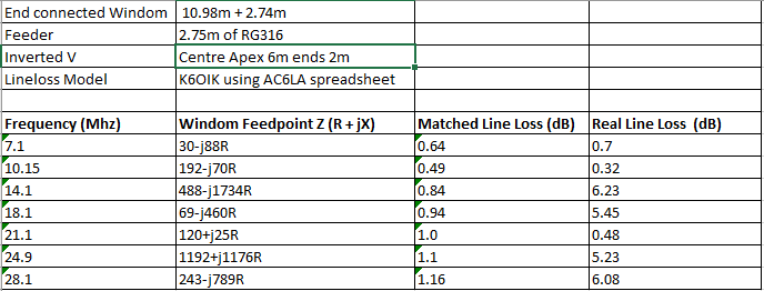
This gives much improved loss figures; I was quite surprised by those for 7.1 Mhz and had to enter the values in the table several times to check I hadn’t made a mistake. If I have, please feel free to correct. However, in my experience on air, the antenna will still not radiate as well on 7Mhz due to it being only a 3/8 wave on that band. As for the other bands, using a KX2 on 12W output should give around 2.5 - 3W erp (depending on how much feeder you use), which for CW works fine. I guess it’s the curse of being a CW operator, even mediocre antennas seem to work well.
As for the 60m version (27.3m with 5.475m RG178), I decided a Ruthroff transformer at the feedpoint is probably the best way to proceed. They are very easy to make with a bit of ferrite bar and some coax:
It’s just a question of getting it as small as possible to reduce weight on the antenna wire.
For those wishing to build this antenna, please bear in mind, that it is a work in progress. Keeping the lossy RG178 to a minimum seems to be one very important factor. I will post updates once I have a new working version. Any input people have is always very welcome; thank you Heinz for the suggestion on the CMC balun and thank you Gavin for the line loss spreadsheet.
73 de OE6FEG
MattMatt,
Your post above referencing the SOTABEAMS “Antenna Center + 1:1 Guanella Balun” prompted me to take a look at this solution.
When looking at this description, I noticed 2 things in particular:
-
In the winding instructions for the “grey” (?) toroidal core according to Reisert’s method, particular importance is attached to how many windings are to be applied before and after the crossover (although from an electrical point of view that doesn’t matter, at most for the wiring), but that the crossover winding is not numbered and counted. Either way, this balun has 14 turns.
-
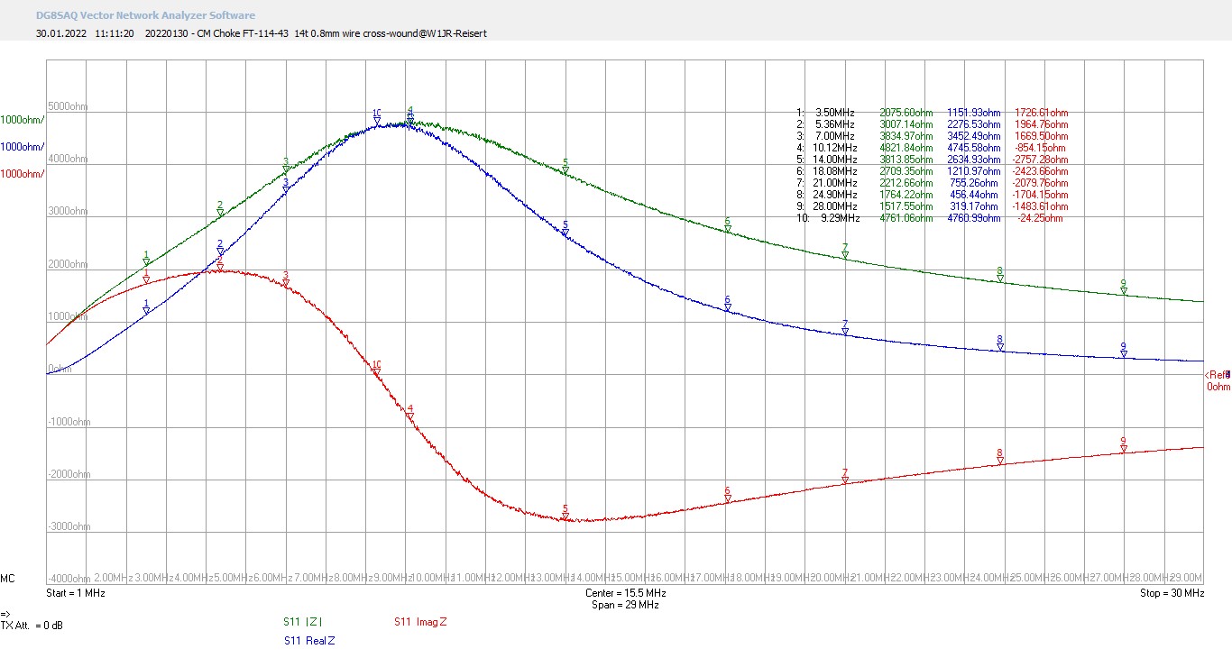
The green graph shown for |Z| (presumably to be understood as common-mode impedance |Zcm|) does not have the typical course dependent on frequency and complex permeability and the values appear to be somewhat good (assumption: FT-114-43 toroidal core).
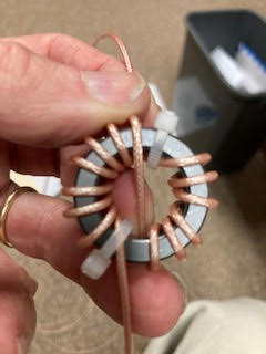
As a reference I used a quick prototype setup with only 1 conductor of insulated 0.8 mm hookup wire.
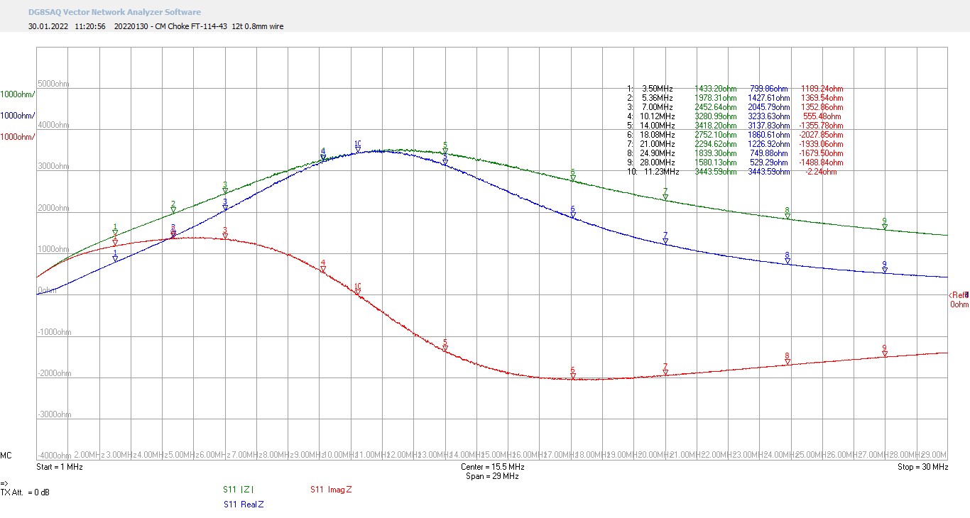
The VNA graphs below show the following:
-
Zcm for the original version with 14 turns
-
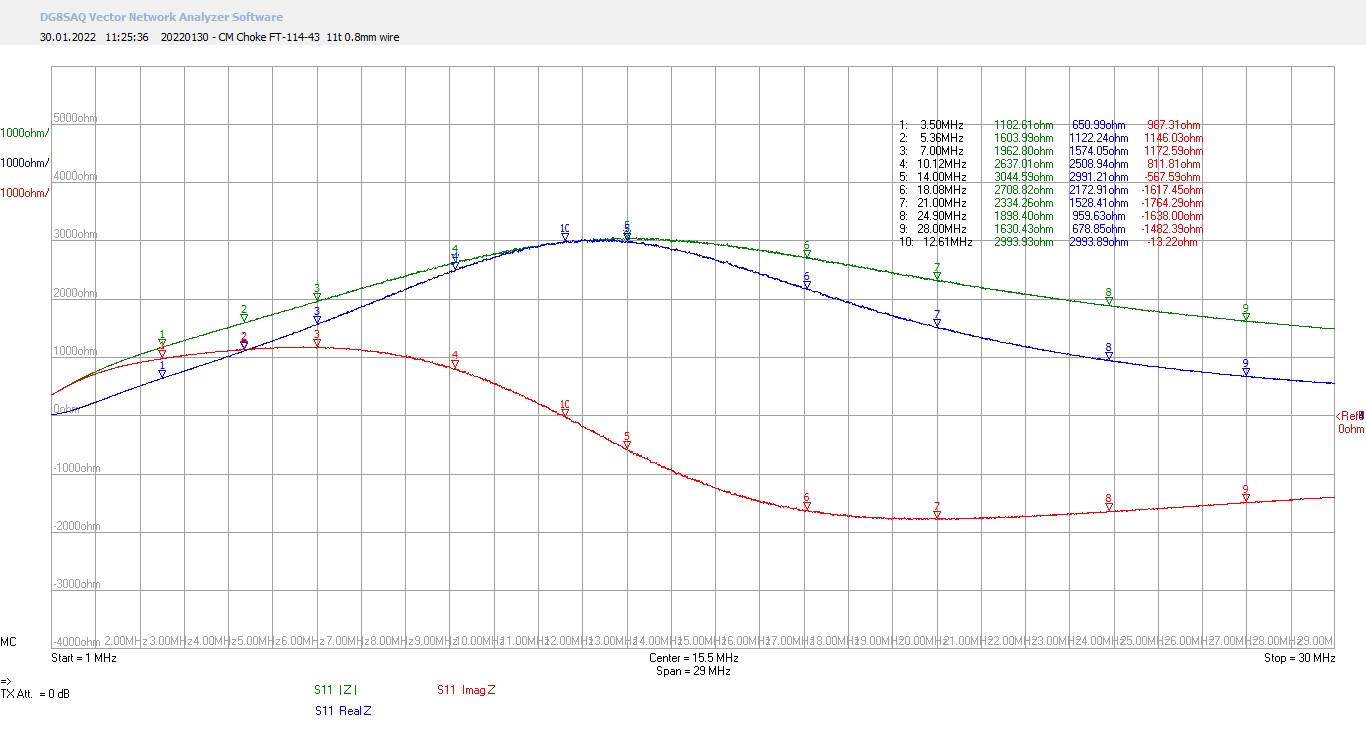
Zcm for a 12-turn version
-
Zcm for a 11-turn version
Marker #10 is set to the self-resonance frequency in each of these graphs.
It can be seen that for applications in the range of 40-10 m or 30-10 m with fewer turns, a larger Zcm value can be achieved on the higher bands.
Pro memoria: Because Zcm occurs on the outside of the coax braided shield, it cannot be measured with an S21 through measurement, but with an S11 reflection measurement (if the conductor is made of coaxial cable: on both sides of the braided shield and if twisted lines: on both sides with both conductors together).
73, Heinz
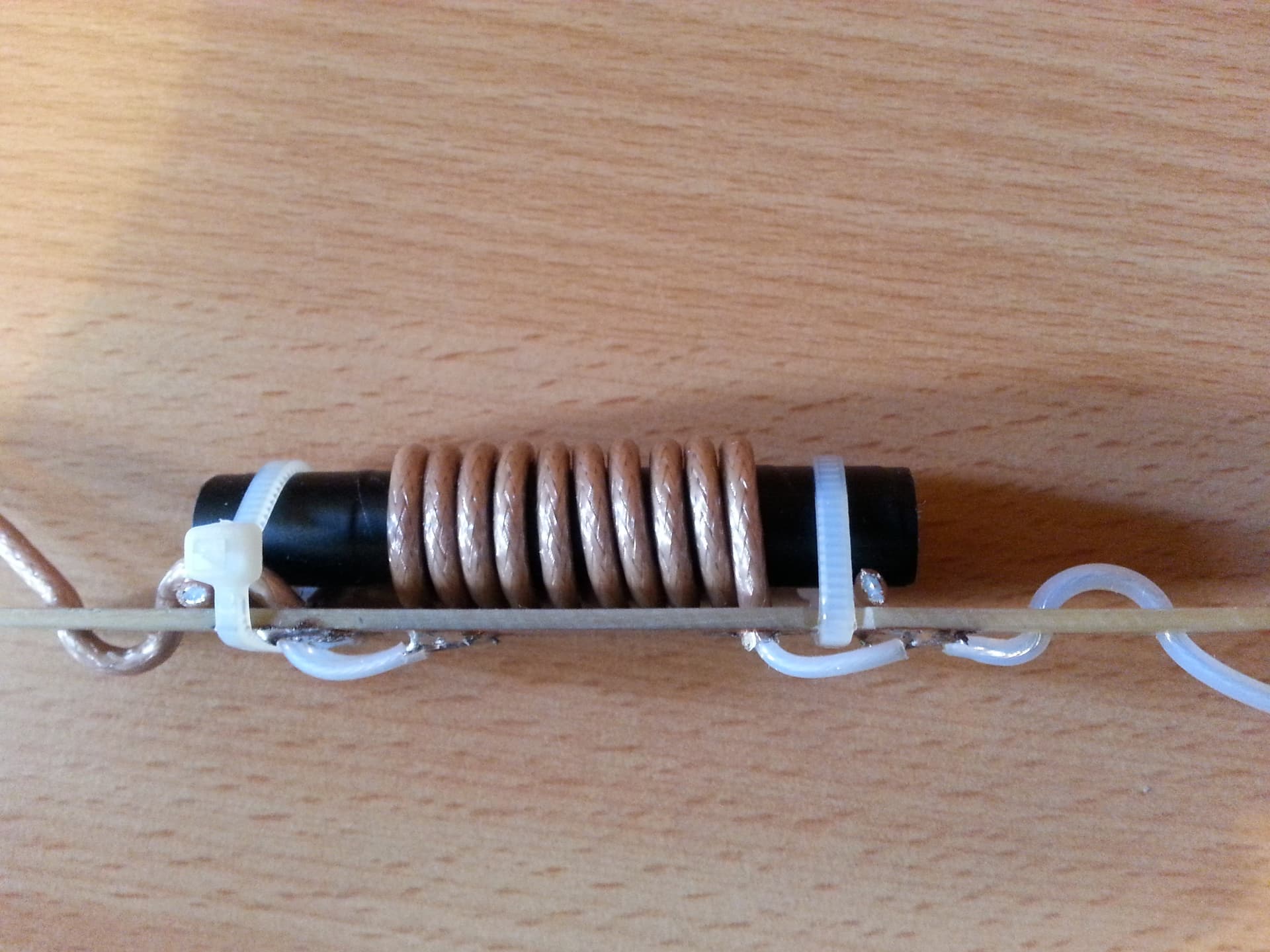
Thanks for that. I had some old PTFE wire from DX Wire lying around, so I put one together right away:
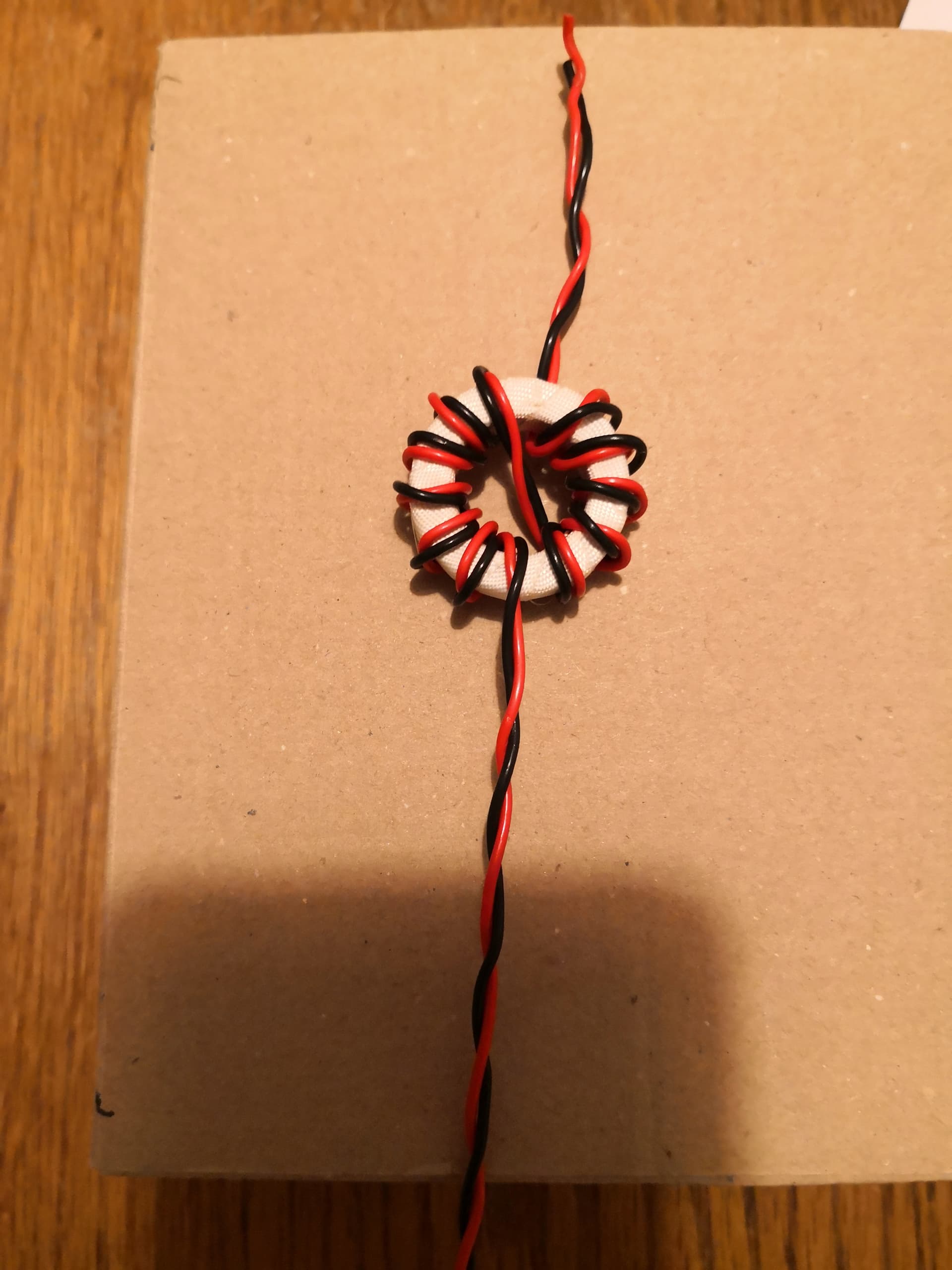
I just have to order some RG316 and a suitable BNC this evening and I can put the new version together.
73 de OE6FEG
Matt
If you wind the balun like that don’t you get 6 turns clockwise and 5 turns anti-clockwise, cancelling them out?
Hello Matt. I built your original design (3.65m feed from toroid to feed point, 18m radiator before trimming) but using just the single toroid 114-43, with 7+6 turns. I have about 6" more feed from BNC to toroid. I deployed it in an inverted vee and tested for dips. I have not yet trimmed it. I got three dips:
40m range 7.7:1 swr
20m range 2.4:1 swr
15m range 2.1:1 swr
Is this what you would expect?
Thanks,
Scott
Do you have a VNA plot? That would make it much easier to say. You could try adding more turns to the ferrite and see if the SWR goes down. On the untrimmed antenna, Fres usually starts off around 6.6 Mhz and rises to about 6.8 Mhz when you get the dip just right for 20m
73 de OE6FEG
Matt
Matt, I beefed up the toroid from 7+6 to 10+9 and it had a noticeable effect. The SWR dips now are:
40m range 4.9:1 swr
20m range 2.0:1 swr
15m range 1.9:1 swr
I can’t do VNA with my analyzer but I note below the dips in the X value and related SWR and R value, if this adds anything:
…X dips…SWR…R
40m range…40…5.0:1 swr…14
20m range…0…3.5:1 swr…14
15m range…36…2.0:1 swr…60
I could go with the two toroid design. Would you comment on the data? Tnx again.
Scott
Those values look much better. They will come down more as you trim the antenna. Trim it for best resonance on 20,15 & 10 and leave 7 Mhz a bit long. I would stick with just one toroid. Much cleverer people than me have made this antenna with one toroid and say that it works. The worst that could happen is that you have to use a slightly bigger toroid.
73 Matt
At least in context of a KX2 with ATU, I’m unclear on the benefit of this antenna. I’ve tried a number of antennas with my KX2 and haven’t yet found anything that outperforms a 54’ wire with 17’ counterpoise, both connected to a BNC binding post connected directly to the radio. That combination gives me 40-10 at 1.5:1 or better SWR (closer to 1.1:1 on most bands). I’ve made contacts on all supported bands with it as well (once during a single activation I logged contacts on all but 15m).
I’m not criticizing the design, just trying to understand what improvement is provided.
Chris
Hallo Chris
Of course you can work with it… I do that too… the antenna I use for 95% of all my activations is the antenna HB9TVK/1 described in the comparison.
It is incredibly fast to set up (just push the longer wire vertically up the mast and toss the shorter wire to the side - done) and since I often do several activities in one day this is a big advantage. The tuner in the KX2 makes from 10 - 40m a super SWR and even 60m still goes… with a bad SWR = / < 3.0
And yes - it radiates nicely vertically and works for DX too.
But if it may be a few db more, it is good if the antenna itself is in resonance.
I always have a cable from the base of my antenna to the KX2. This simply allows me to find a more comfortable place to sit, which is not always necessarily directly under the antenna.
The kabel is simply little more than 3m RG 174, which ends at one end as a balun on a 140-43 toroid. This balun I have at the base of the antenna.
For longer activities (eg EU - NA party) I have an endfed for 40/20/15/10, because I then use a small PA without tuner. (on the other bands I change it directly to the KX2 and use the tuner)
For these applications I turn the RG174 and have the balun at the antenna socket of the pa. The shielding is the 0.05 Lamba counterpoise directly behind the 1:49 balun.
I recently reversed this cable and measured the endfed with the NANOVNA. Suddenly I had a usable SWR of 60m - 30 and on 20 / 15 / 10m too. But when I then connected the TRX, I could see that the antenna performance was significantly worse. SWR is not everything…
![]()
73 Armin
A dummy load has perfect SWR.