Simple Resonant Multiband Antenna for Use with KX3/2 and Internal ATU

There seems to be a lot of interest in antennas that can be used with an internal ATU, such as that found in the KX3/2/1, so I thought I would share a rather clever design that was given to me by G3UNA, who in turn got it from M0RZF:

http://www.m0rzf.co.uk/styled/

It is generally called an End Connected Windom or ECOCFD. The name says ‘end connected’ and not ‘end fed’ for a good reason. It offers almost all the advantages of an EFHW antenna (resonance and no long coax feeder to carry), whilst cleverly utilising common mode currents to feed the antenna as one would a normal off-centre fed dipole, yielding a much more manageable feed-point impedance in the range of a few hundred ohms, rather than several thousand. Below is a basic diagram of an antenna made for 40 - 6m:

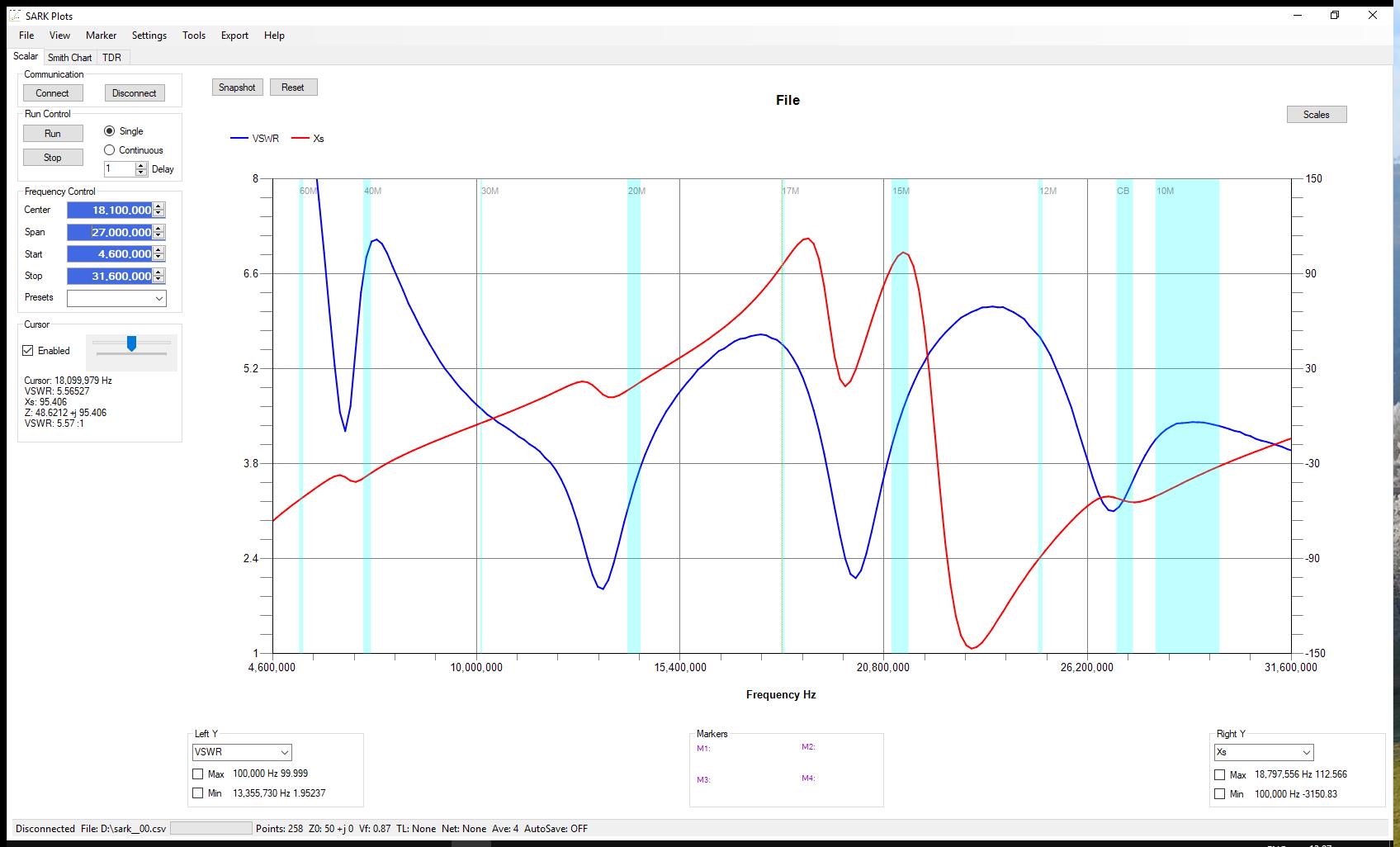
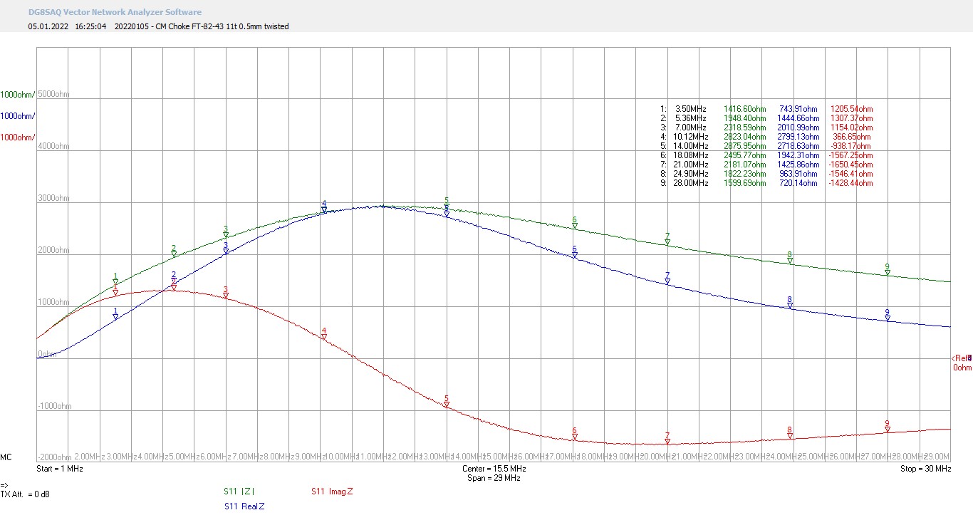
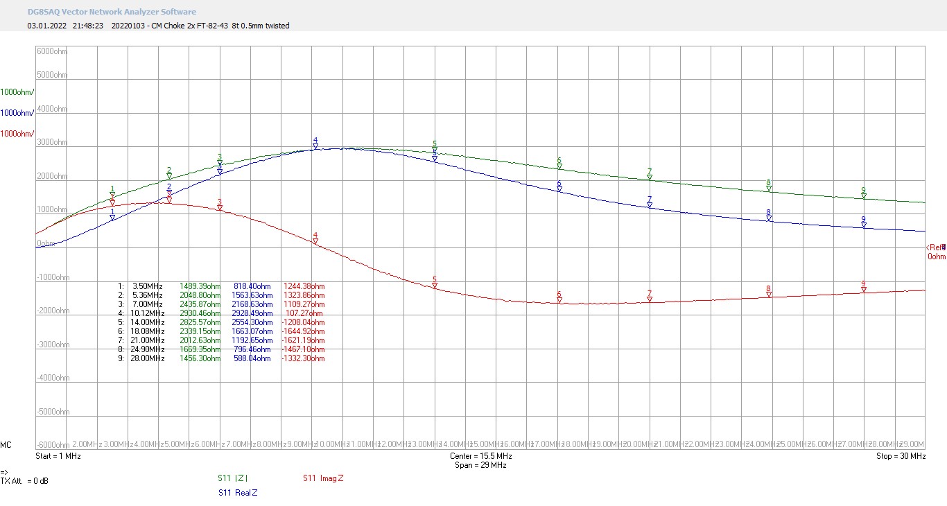
I have learnt quite a bit in the course of building quite a few of these antennas. Firstly, getting sufficient impedance from the current balun is of paramount importance. Although there is some leeway with the choice of ferrite material, at least one ferrite should be type 43 if the antenna is for 80m and above. Type 31 would be needed for 160m. Two ferrites give a big increase in impedance, and having them different sizes helps prevent any capacitive coupling between the cores (so I’m told). Below is a plot taken from a version that used two type 61 ferrites, an FT 114-61 and an FT 82-61:

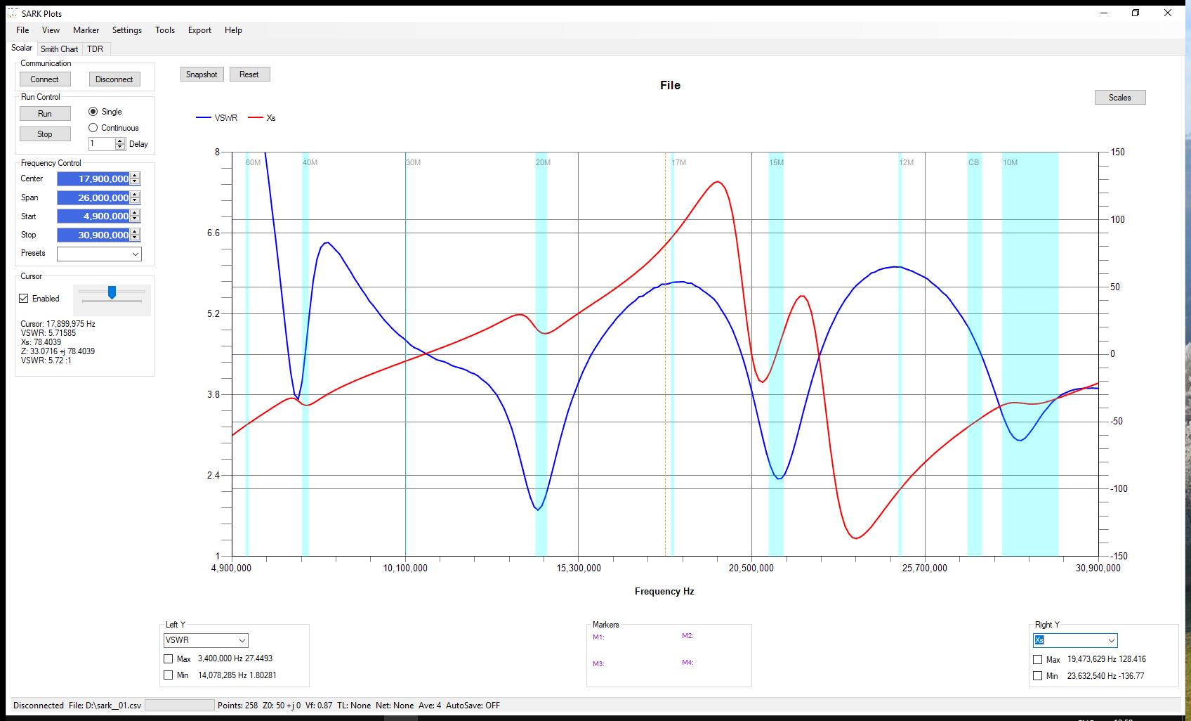
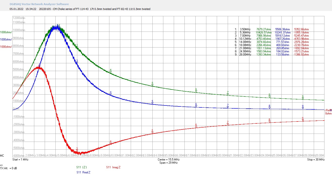
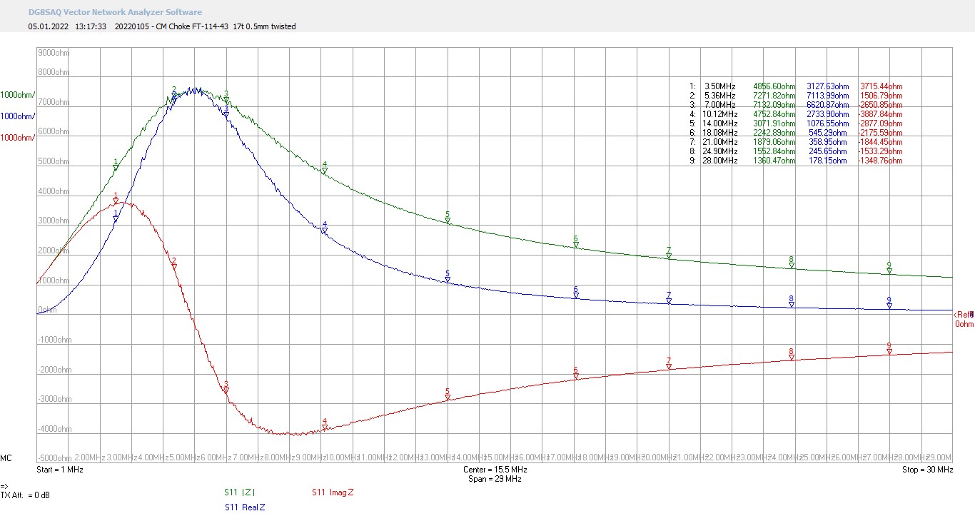
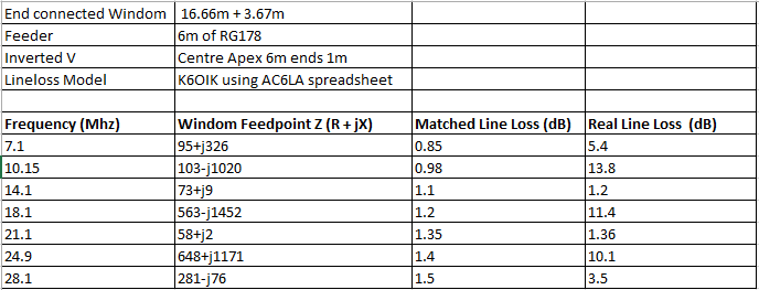
What interests me here is that F-res at 40m is much higher than it should be given the readings for F-res at 20m and above. Compare that with the plot I made for exactly the same antenna, but with the FT 114-61 swapped for an FT 140-43:

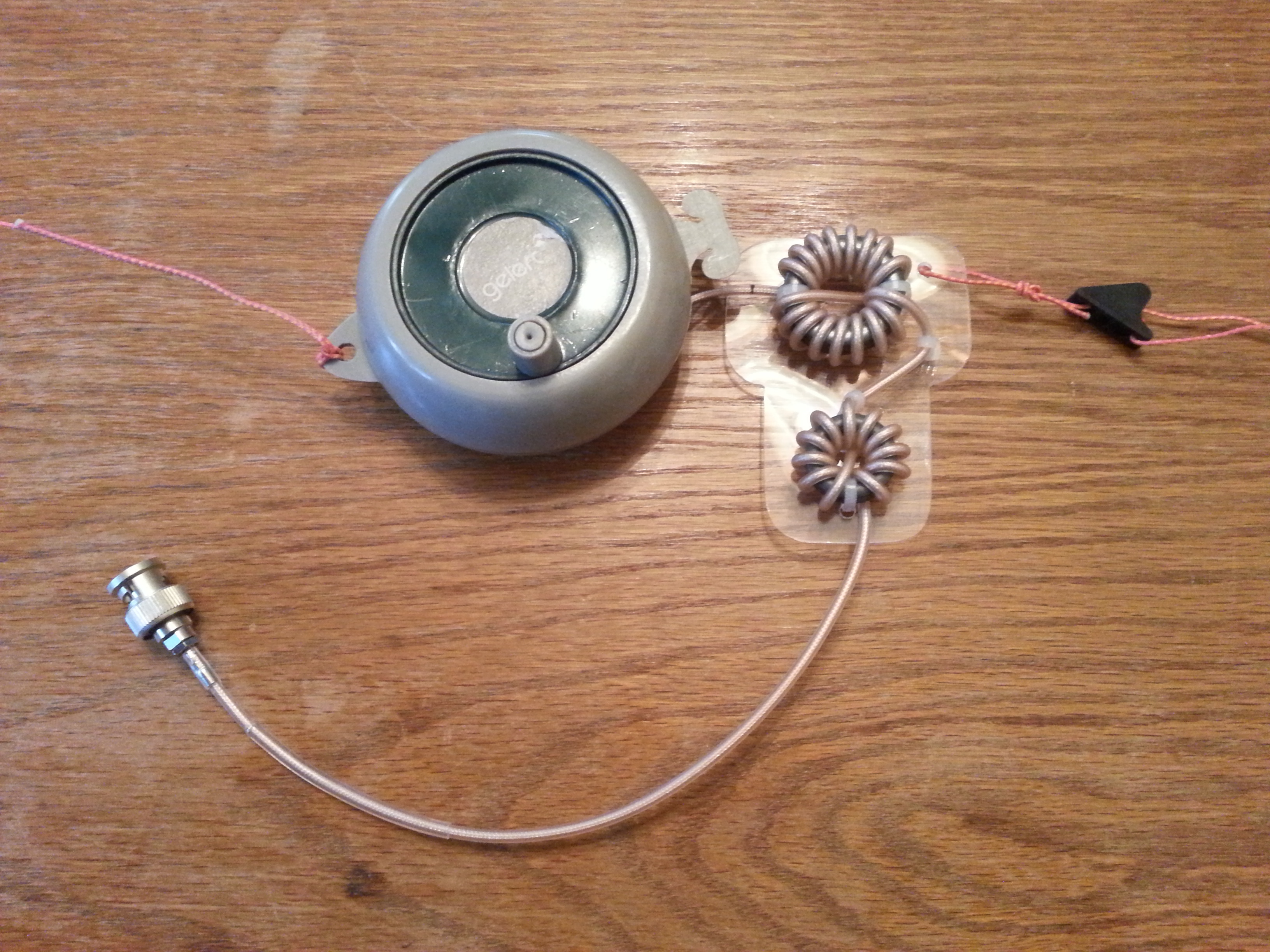
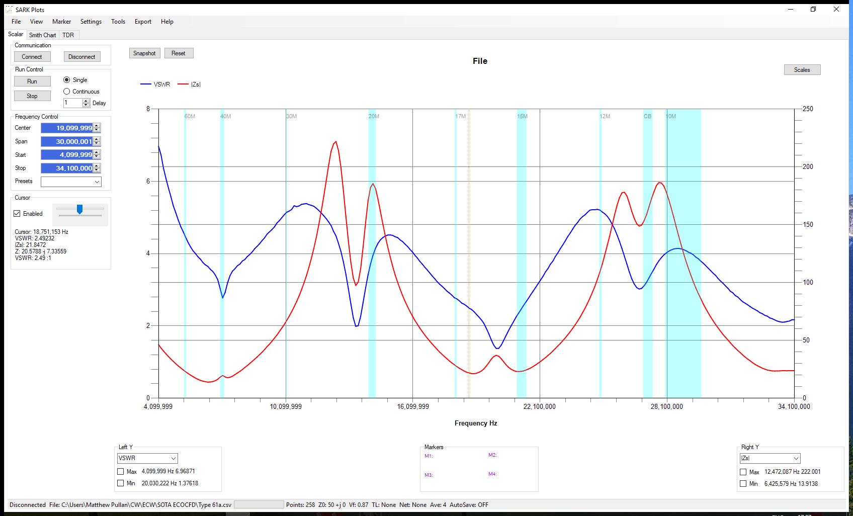
Here we see that the impedance plot is almost completely the opposite of the first version and looks much more like it should do. I should point out that the antenna would probably work fine with just one FT 140-43, and maybe even just one FT 114-43; that is for other people to experiment with. The one other point to bear in mind is that RG178 coax, just like RG316, has a rather thin PTFE sheath. This sheath got damaged on some of the first versions I made, especially where it was wound round the toroids. So, in later versions I began to protect the section of coax that was wound onto the toroids with some clear heatshrink tubing. Applying such a long length of heatshrink takes a lot of careful work from one end to the other, so as to avoid air bubbles. The finished article can be wound very conveniently onto a camping washing line reel:

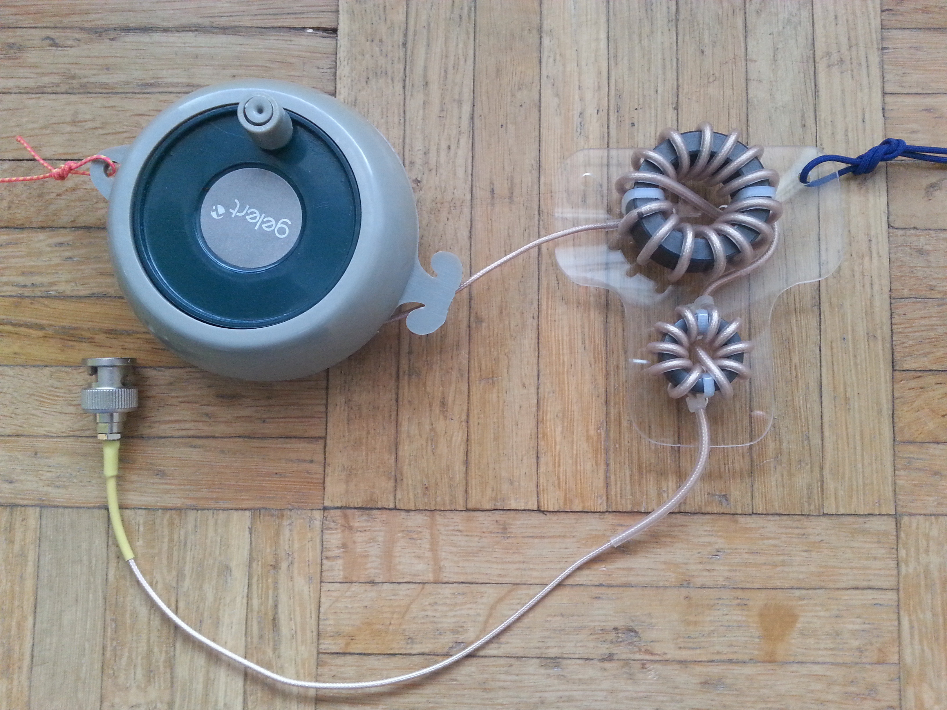
As can be seen, I mount the ferrites on a piece of 2mm acrylic. It is best to use some adhesive lined heatshrink for the feedpoint connection between the PVC wire and the centre conductor of the RG178. There are only 7 strands of very thin wire in that centre conductor, and yes, they have snapped on me in the field. The finished antenna weighs about 230g, but this could be made considerably lighter by someone with the time and inclination. It tunes up (with a KX3) and works acceptably well on all bands from 40m to 6m, I have had good DX contacts from this antenna on every band it can tune. Below is a WSPR plot using 1 watt TX power on 40m from the antenna (same design) that I use as my main station antenna:

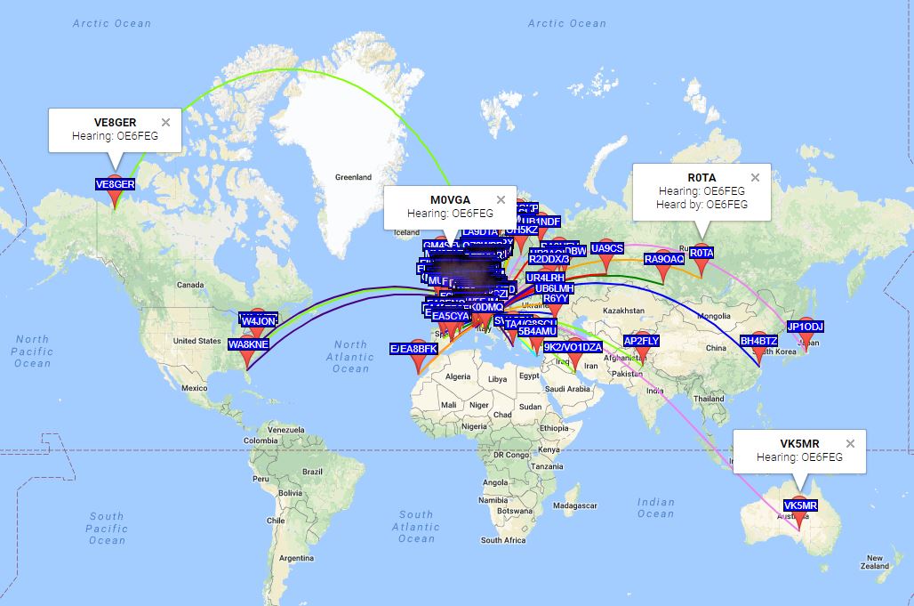
Of course, some bands will work better than others. You can, of course, make a perfectly functional, if somewhat heavier, antenna with just RG174. SOTABEAMS sells RG178:

https://www.sotabeams.co.uk/coaxial-cable-rg178-per-metre/

I use this antenna all the time with my KX3. I only swap to a Fuchskreis when there is likely to be a lot of BC and commercial interference, as the Fuchskreis give excellent out of band rejection. I’ve posted it before, but here is my log from the 03/01/2018:

This antenna works!

       de OE6FEG / M0FEU
                                         Matt
9 Likes

very interesting, I’d like to try it eventually. I assume you’ve experimented a lot to optimize lengths.

Barry N1EU

Actually no, I haven’t experimented a whole lot with lengths. I presume that M0RZF has done most of the tweaking. In any case, it seems widely accepted that a 5:1 split gives better performance over more bands than the traditional 3:1 split. Due to breakage, my short leg is now a bit shorter than 3.65m; it still works fine.
Matt

1 Like

Hi Matt,

Just sended you a PM.

73

Laurent de F8CZI

I still use the KX1, and with only about 3 watts output on a good day, I have been struggling with antennas. The antenna I will try out next time is very similar, 33 feet of RG174, to a balun (brings my SWR to +/- 2:1 on all relevant bands) and about 28 feet of 20 or 24 gauge wire either thrown into a tree or on a mast.

I used the RBN network and had good results, although WSPR seems to have more receiving stations (I need to get that). I think that set up will do the trick, but the one you posted seems like an interesting project too.

Thanks for the post.

Mike

Thanks for posting your antenna design.

I am pretty new to ham radio, SOTA and antennas.
I like to reproduce your design.
I got the material but have a few questions:

  1. How do you typically setup this antenna?
    Inverted V?
    Do you use a pole? (Which one?)

  2. The schematic says ‘Antenna Wire 18m (before trimming)’.
    I suppose the antenna has to be shortened by a few millimeters/centimeters for
    optimal SWR on all bands.
    How does the trimming procedure work?
    I have a general idea, but would like to understand how you did it.
    Did you use an antenna analyzer on all bands, then shorten the antenna until you got an acceptable SWR?
    If you used an antenna analyzer, which one?
    Could I just use the built in antenna tuner.
    How did you setup the antenna while trimming it?

  3. Do you connect the BNC as shown in the picture directly to your radio?
    Could the feed line (wire between BNC and current Balun) be longer (lets say 1m) or should it be as short as possible?

Thank you for you input.
Friedrich

1 Like

Hello Matt,
Jorge EA2LU sent me about a year ago an article describing how to build this antenna and given that I was in the process of trying to set-up some type of simple station at the rental appartment we (my family and I) are living in now in Pamplona city, I decided to build it and get it installed in the balcony of the rental apartment exactly the same way I had a EARC antenna http://www.earchi.org/92011endfedfiles/Endfed6_40.pdf

So I did and the comparison I carried out demonstrated that the EARC antenna with counterpoise I had installed in the balcony was notably superior to the newly built according to the USA RBN skimmers copying my signal at the time. Various skimmers in NA were copying my signal when transmitted with the EARC antenna and not copying it when transmitted with the newly built one.
Once seen the results, I immediately took it off the balcony and it’s been living in a tray of my shack desk since then.

Although the EARC antenna buiding instructions say a counterpoise is not necessary because the shield of the recommended 5m of coax are acting as a counterpoise, I can tell you that I have tested the EARC with 5 m of RG58 with no other counterpoise and the same antenna with 7m of wire as a real counterpoise and this last is far superior.
That’s what I currently have installed in my apartment balcony.
That’s what I always use now in most of my SOTA activations.

Perhaps, the use of a counterpoise wire on this antenna you are proposing, Matt, might improve it’s performance.

73,

Guru

1 Like

Hi Friedrich,
the antenna in my post is basically an off-centre fed dipole, so it can be set up in any configuration that you would normally set up an OCFD. I personally use it with a 10m fibreglass mast as I like to get as big a signal out as possible when I’m on a day trip. I set up as an inverted vee, but straight, vertical, inverted L etc, will all work. You trim the antenna down much the same as any dipole: a few centimetres at a time. An antenna analyser is required for this, I use a SARK 110. I occasionally connect the BNC directly to the KX2, but I usually take 2-3 m of DXW-174, so that I can get the balun higher up off the ground in a tree if possible. Remember to use adhesive lined heatshrink between the centre conductor of the RG178 and the wire section, that centre conductor is very fragile.

I’ve heard it said that a counterpoise often improves performance with an endfed antenna close to a building, perhaps this is happening in your case. However, as the design I use is basically a dipole, I don’t think a counterpoise is appropriate. In an ideal world, there needs to be little or no current on the feedline, otherwise the antenna will appear longer than the resonant dipole it is intended to be. At home, I certainly have the coax earthed at the connection point on the roof and at the transceiver.
I notice the EARC did particularly badly in the WSPR tests:

But again, that was away from buildings and maybe was missing the all important counterpoise.
73 de OE6FEG / M0FEU
Matt

This shall be equivalent to the type of counterpoise I have for my EARC in the balcony, where a very short wire of about 20cm coming out from the 9:1 unun is connected to the 9m long metal (steel) fence of the balcony, which might possibly be connected to the whole building ground. Your grounding of the coax at the roof feed point surely enhances that antenna performance.

I think so, and according to my testing of the EARC antenna on summits, it made big difference.

73,

Guru

1 Like

Both my antennas at home are earthed on the lightning conductor network, which provides a good enough ground plane to allow me to use a mobile centre loaded whip for 80m and brings the SWR down to 1.3 without a tuner. With the OCFD, it is important to remember that whilst it is connected at the end, like a normal EFHW, the actual feedpoint is one fifth of the way along the antenna where the centre conductor of the coax meets the long pvc wire. The impedance at this feedpoint is not more than 300 ohms, easily dealt with by most auto ATUs. If the coax were grounded on the antenna side of the current balun, close to the true electrical feedpoint, it would no longer be a dipole, but something like a long wire working against a ground. That said, a relay switch to ground on the antenna side would perhaps allow a 20m long OCFD (lowest band 40m) to be tuned up and radiate effectively on 80m, which would be useful for restricted spaces. Here is an updated link to the page maintained by M0RZF on the End Connected Windom:

Whilst the grounding helps, the hybrid SDR function of the KX3 allows me to use full pre-amp on 80m whilst only getting about S1-2 noise in HDSDR. On the KX3 side, there is about S8-9 noise in the receiver. Antennas aside, I wouldn’t be on 80m at my home QTH if it wasn’t for HDSDR.
73 de OE6FEG / M0FEU
Matt

Hi Matt,

Thank you for the clarification. I have built the antenna by now.
Still need to get the antenna analyzer for trimming.

Also I am interested in your 10m fibreglass mast.
Is ist a telescope mast? If so, how small/short does it get and how heavy ist it?
I have researched quite a few different versions and can’t decide which one to pick.
I rather had one that collapses to <0.8m to fit my backpack.
Could you please share the type/brand you are using?

I also see a lot of people using fishing poles. Did you ever try one yourself?

73 de K2CI
Friedrich

1 Like

I have just finished a new, lighter version of the antenna:

Changes I made to this antenna include using a thinner gauge (1.1mm) wire for the long leg and a smaller acrylic T piece made possible by the use of a smaller toroid. For this version I used an FT 114-43 and an FT 82-43. The SWR plot is similar to the one made with the FT 140-43. Here is the version before trimming:

And after:

You may notice that I have optimised this version for use on 20m, which I normally do. I made the short (coax) leg 2cm longer, so that if there is a breakage in the field, there will be a bit I can cut off without the short leg getting too short. After trimming, the dimensions are:

Short Leg: 3.67m
Long Leg: 16.66m

This new version weighs 184 grams, but there is still scope to make the antenna even lighter by using a light gauge of enamelled wire to make a bifilar winding on just one FT 82-43. In the field the antenna is indistinguishable from the previous version, so much so that I simply plugged it into the KX2 and started transmitting; no need to re-tune. That’s one thing I like about these antennas compared to a random wire: the SWR is very stable regardless of how the antenna is set up. Here are a couple of photos from a few weeks back when I was QRV on the border with Hungary:

It is the old version in the photos, but it goes to show just one of the many ways this antenna can be used.

            73 de OE6FEG / M0FEU
                          Matt
2 Likes

I am doing a video series on how to build this antenna:

Hope you find it useful.
73 Matt

3 Likes

Part 2 is finished:

73 de OE6FEG
          Matt
4 Likes

Hallo

Definitely an interesting antenna -
somehow it reminds me of the W3EDP

73 Armin

Matt,

When I saw your “artwork” of a common-mode choke some time ago, I was a bit surprised:
Why is a CMC with such a special common-mode impedance Zcm needed for an OCF antenna of this design?

The VNA plots below show the approximate Zcm (frequency-dependent) for your original version with baluns on the toroidal cores FT-114-43 and FT-82-43 in series and, for information, for each of the two baluns.
The VNA measurements were carried out on twisted pair wound Guanella 1:1 baluns.

Please note that the tolerances of the ferrite material and the cores are quite wide.

The Zcm characteristic resulting from a toroidal core FT-82-43 with 11 turns twisted pair should be well suited.
For transmission powers in the range of 10-15 watts, 2 of these toroidal cores (stacked, not in series) with 8 turns could be used.

BTW, if anyone is interested in how to measure Zcm incorrectly or correctly, Owen Duffy’s contribution “Baluns - show me the numbers” might be worth reading.

73, Heinz


2 Likes

I don’t quite understand your question, but I’m assuming that you are not asking me why a CMC choke is needed on an OCFD.
Firstly, the common-mode impedance is not intended to be special. I just tried to get as much impedance as possible whilst gradually reducing the size of the balun.
I’m afraid I’m not an expert on antenna design, but I dare say you are entirely correct in your calculations. However, I prefer to use coax rather than bifillar windings as it does not require any waterproofing. I used two toroids of slightly different size as the original designer of this type of antenna (M0RZF) suggested that two different sized ferrites would increase impedance whilst reducing capacitive coupling. I did not calculate the impedance required, but rather worked by trial and error. I try to put as many windings as possible on the ferrite whilst staying short of 1/4 the wavelength of my highest frequency (10m = 2.5m). It has been pointed out, that the balun would work fine with just one ferrite, or even no ferrite; if the antenna was connected directly to the rig. My preference was always for an antenna that can be mounted high in the trees and then connected to the radio via a short piece of feeder. I always accepted that 2 ferrites may be overkill, but I tend to go by how much hum I get in my noise cancelling headphones, which are rather sensitive to CMC, mainly on 7MHz.
73 Matt

1 Like

As Heinz posted this, I decided to share some analysis I did last year of Matt’s original version. Its an interesting antenna if you want a 3 or 4 band end fed antenna with coax feed, say out an apartment window.

Good antenna on 20m & 15m. Might be possible to tweak it further to get good match on 40/20/15. However like many coax fed antennas where the impedance is far from 50 Ohms on some bands, the feeder loss is very high on these bands. I concluded it was not the best choice for multiband SOTA use with an ATU.

Modelling was done on Eznec in a typical SOTA layout, then these feedpoint impedances applied to the AC6LA line loss calculator spreadsheet. I guessed 6m of RG178, which covers the 3.67m in the antenna + the chokes + a tail to the radio.

image

73 Gavin
GM0GAV

2 Likes

Ok Matt,

My question was of course to be understood as a rhetorical question.
For me it was/is clear that the designer of this CM choke was not familiar with its functionality and the measurement of its complex impedance.

Please note that my intention was not to criticize, but rather to point out a possibility for improvement and, above all, for simplification.

The VNA plot for the original CMC version shows that the self-resonance is around 5 MHz, which results in a respectable common-mode current suppression on the bands 80-40 and still on 30 m.
However, this is at the expense of the higher frequency bands because Zcm decreases rapidly and continuously.

For a 40-10 m antenna, it would therefore be advisable to design the CMC for self-resonance in the range of around 9-11 MHz.

Leaving out the CMC would mean that the previously short leg of the OCF antenna would be extended to the TRX, because the radiating common-mode current would no longer be stopped on the outside of the coaxial shielding braid. That would significantly change the geometry and properties of the antenna.

Now I wish you a lot of fun and success with experimenting - and especially with portable radio.

73, Heinz

1 Like

Gavin,

You must have overlooked the sketches of the two final versions (slightly above in the thread) and probably also the different coaxial cable sections

  • RG178 is only used for the short leg of the OCF

  • RG316 for winding the toroidal cores and an approx. 0.5 m tail

  • RG174 for the feed line of approx. 6 m

BTW, The EZNEC simulation of the 13.72 m OCF, source placed at 20% from end, wire horizontal at 6 m height, results in the following impedance values:

40 m: 30-j88R
30 m: 192-j70R
20 m: 488-j1734R
17 m: 69-j460R
15 m: 120 + j25R
12 m: 1192 + j1176R
10 m: 243-j789R

73 gl, Heinz

2 Likes