Hi everyone,
I just added a translation to the following article:
This antenna can be connected directly to the TRX and works very well. Building is simple.
Only drawback: Its a monobander ![]()
73, Roman - DL3TU
Hi everyone,
I just added a translation to the following article:
This antenna can be connected directly to the TRX and works very well. Building is simple.
Only drawback: Its a monobander ![]()
73, Roman - DL3TU
Hi,
Are there any dimensions available?
73
Ron
VK3AFW
Ron,
Go to the linked website. Scroll down to the English version. The first link in the English description will take you to a German site - Chrome will give the option to translate automatically. The second article on the page is “The half-wave coaxial antenna (LHKA) after DL5PC / DJ8EI” after translation. At the bottom of the article are some links, including an Excel file to do all the calculations.
Good luck,
Peter VK3PF
Ron,
here is the direct link to the (almost self explaining) Excel- Calculator:
http://www.darc.de/fileadmin/_migrated/content_uploads/Excel_Rechner_fuer_Lambda_Halbe_Coax_Antenne_II.xls
If you have trouble using it, just let me know.
Here is the direct link to the construction manual (unfortunately in German):
gl, 73, Roman - DL3TU
Thanks very much Roman and Peter. A simple roll-up mono-band antenna makes sense for a mono-band rig.
73
Ron
VK3AFW
… now I created a new calculation spreadsheet. I hope it’s self explaining.
The link can also be found in the above mentioned article.
http://www.dl3tu.darc.de/EFHW-Dipole_Calculator.xlsx
Happy antenna- building!
73, Roman - DL3TU
H Roman,
The link to the HB9ACC presentation on mods-ham.com doesn’t work. There appears to be a problem with this site as it comes back as “Diese Domain ist unkonfiguriert.”
The link with this problem in both the German and English section of your interesting article is: http://www.mods-ham.com/21_Rund%20um%20die%20Antenne/Rund%20um%20die%20Antenne%20Teil%207.pdf
I guess the domian will get fixed at some point, but I just wanted to let you know.
73 Ed DD5LP.
Hi Ed,
thanks for the hint!
It seems Max, HB9ACC, has removed the files from the server. Hopefully he makes them available again as they are really useful.
73, Roman - DL3TU
Actually it’s the complete domain - just try going to www.mods-ham.com and you get the same message.
I’ll be building one of these antennas for 20m (14.285 SSB) in the next few days - looks like a great idea - an EFHW that doesn’t need an ATU!
73 Ed.
… 20m is my favourite one - workes like a charm and can be deployed on a 10m fiberglass pole (if wound in a few turns around it). The coaxial stub can actually lie on the ground without any impact on the performance.
If you find it cumbersome to take care of the T-piece and the short coax, you can put both pieces of coax in parallel. Fix them with some shrinking tube and solder both ends into one plug large enough to hold two cables.
Electrically it’s the same but looks like the short coax has gone.
good luck then, 73,
Roman - DL3TU
Hi Roman
I have a 10m version from Herbert OE9HRV. Very happy with the antenna performance, of course 10m propagation has to open. With the same antenna I have worked UK chasers from VK1 summits.
You may also consider the antenna design as J-Pole.
73 Andrew VK1AD
Here is a picture of my 10m version used at Booroomba Rocks VK1/AC-026 (Dec 15)
The stub (L1) is folded back on (L2) and the common feed point fits inside a PL-259 used for RG-213.
This is a good view of the stub L1 and L2 side-by-side. (Dec 15)
73, Andrew VK1AD
Hi Andrew,
excellent! A picture is worth a thousand words.
73, Roman - DL3TU
Hi Roman (et al),
Well I built my 20m version - no T-piece, just soldered together. Cost of parts €0,00 as I aready had a lngth of coax with a plug on one end and I have some really llightweght (24 AWG) PC boardpatching wire which I use for antenna projects.
The results on the Analyser after building to the dimensions from the spreadsheet -
Resonant freqency 14.285 MHz (as required by me for SSB operation),
SWR 1.42:1
IZI = 52.4 ohms
R = 49.4 ohms
X = -17.4 ohms
C = 634 pf.
Very impressive for an end-fed simply cut and soldered - no trimming at all was neccessary!
Now I just need to get it on a summit to test it out.
I suppose I should call my implementation a “Helical vertical” as I had to wind the wire around the 10m GFK mast a lot to make it fit in the height available - in fact the lower coax portion was half on the ground.
73 Ed.
Hi Ed,
I’m glad you achieved such good results at the first shot! Congrats 
From my experience it’s no problem if the coax is lying on the ground as it is supposed to carry no RF on the outer side of the shielding.
The only thing one may want to watch is the open end of the coax (where the antenna wire is connected). At this point the voltage reaches its maximum - almost 1 kV peak with 100 Watts. Some shrinking tube is recommended to protect this point against mud and moisture (as can bee seen in VK1AD’s photo).
Good luck with the new antenna,
73, Roman - DL3TU
The Archive knows all!
Hi Roman - yes that point in the antenna is well insulated. I think with some closer winding of the open (but insulated) wire piece on the 10m fibreglass pole, I should be able to get more of the coax on the bottom of the pole.
Looking at perhaps gettng out to a summit with it tomorrow to test it out (Just EU though, I wont be getting up early enough for Long Path to VK).
73 Ed.
Thanks Bruce,
Looks like Web archive is like the “way back machine” site (or is this the same site perhaps?).
Great to get the PDF file. For those who can read German, this is a nice collection of descriptions of interesting antennas from Max Rüegger HB9ACC, well worth the read.
Once I am happy my 20m EFHW vertical works, I’ll build another one using the thin coax (adjusting lengths for the velocity factor of the cable) and that will then be a very lightweigth and compact antenna. It’s not bad with RG58 but given I only operate mostly QRP going to the thin lightweight coax (as long as I insulate the high voltage point well enough) should be a good move.
73 Ed.
Hi Bruce,
thanks a lot for digging out that link! The antenna handbook of HB9ACC is definitely worth reading.
73, Roman - DL3TU
BEWARE OF BETTER QUALITY COAX!
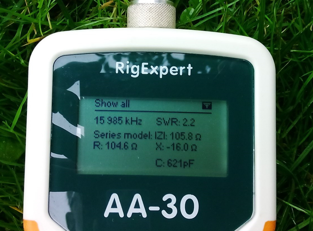
Having had such success with my first attempt, I decided to produce a lighter version using RG-174 coax rather than the RG-58. Well RG-174 has the same velocity factor as the RG-58, so I cut the same lengths and built the antenna. when I tested it though … best SWR 2.2:1 way out of the top of the 20m band!
Checked the connections - all OK. Then I looked at a different site for velocity factors to find that the lower loss, higher frequency, more expensive foam version of RG-174 has a VF of 0.735 not 0.66. What this means is that I cut the coax lengths too short! “RATS” or words to that effect!
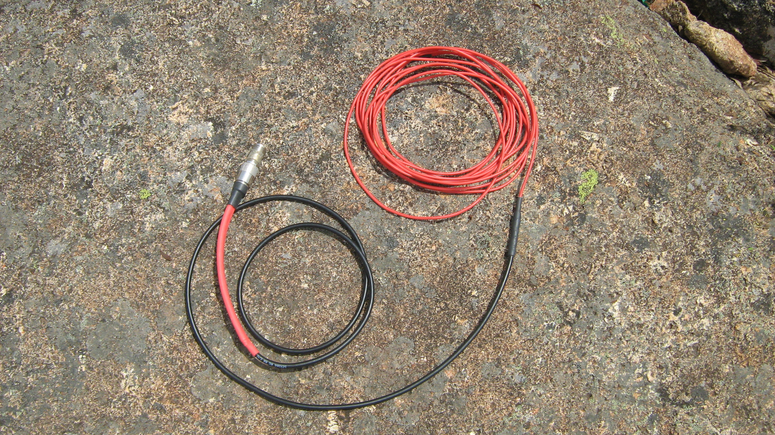
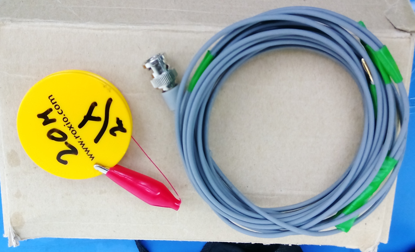
Lets see if I can fix this as the RG-174 version is really easy to pack. I have even added a golden link conector on the end of the coax and the insulated wire section (which winds onto an advertsing gift - YoYo ) to enable easier handling.
(the clip, simply clips to the top of the mast).
Ed.
UPDATE: In the end, with a lot of help from Roman, I found the real problem. The coax which I thought was RG-174 was actually 75 ohm RG-179. Not that the fact that it is 75 ohms rather than 50 ohms is the problem. The problem is that the Velocity factor of the coax is 0.70 not 0.66 (PVC RG-174 coax) or 0.735 (foam RG-174 coax) and of course with the wrong velocity factor the lengths from the calulator spreadsheet were wrong.
After length correction my (now 15 metre J-Pole) made 4 contacts into North America on Tuesday from DL/BE-093 with just 5 watts of SSB, so the antenna works very well and it’s great that it can be packed away so small!