Cable for USB power banks with KD1JV rigs (ATS / MTR models)

I’ve seen lots of postings about designing/building your own power sources using 18650 cells. Being lazy (and not terribly mechanically gifted), I was looking for an easier way, one that would allow me to use the ubiquitous inexpensive off-the-shelf 5V powerbanks.

There was a previous post by Tommy SA2CLC, who was kind enough to even send me some blank PC boards for a power booster. But again, I’m not terribly gifted in such projects, so I kept looking.

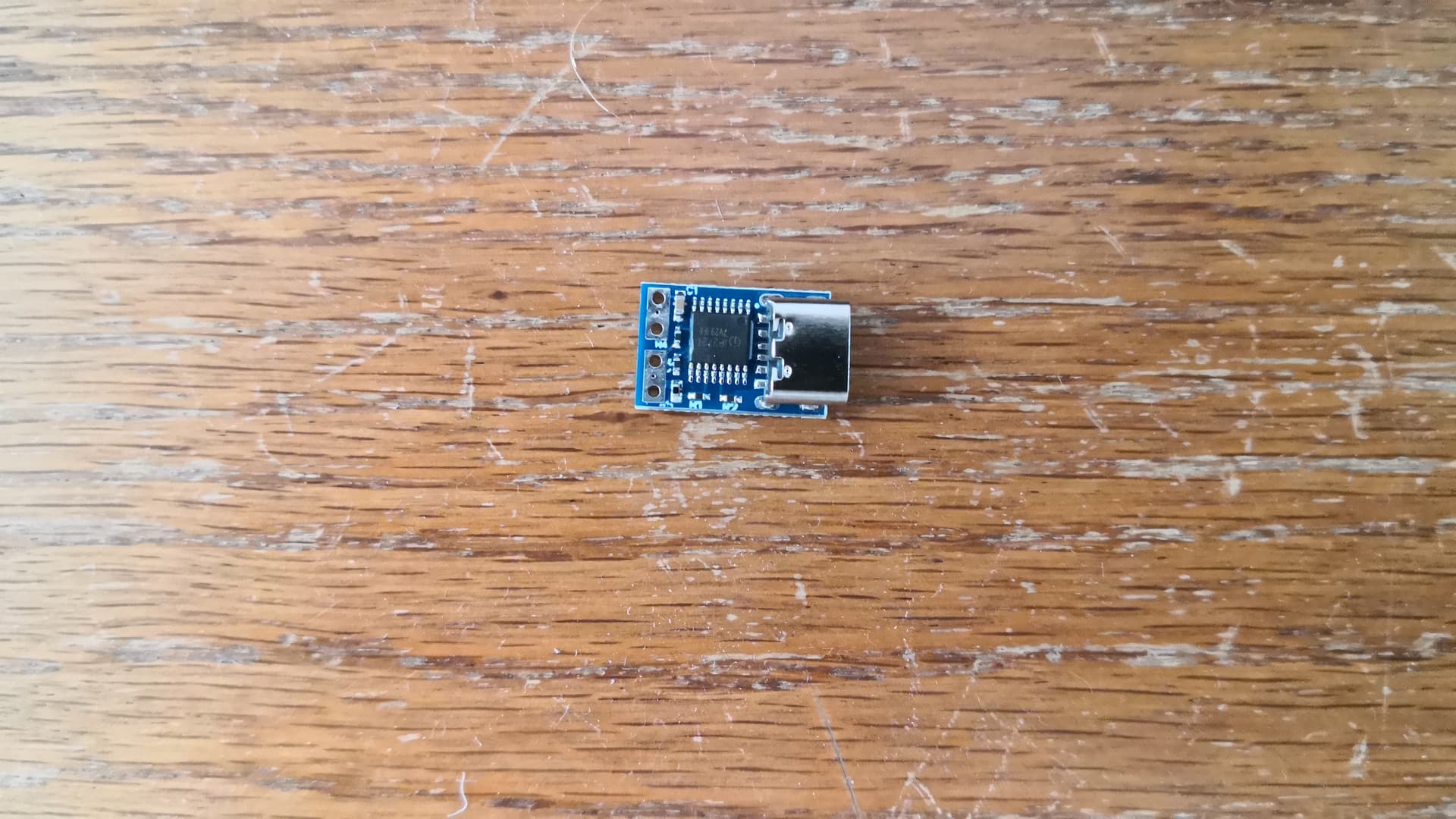
I have found a first solution with the Adafruit Model 2778. I love the idea of being able to pick up a cheap powerbank to use with my MTR-5b with the help of this very cheap ($US 6.50) cable. There is also a 9V version available (Model 2777).

The cable is rated for 500 mA, but the factory got 700 mA out, and I’ve been getting 960 mA out during initial tests using an MTR-5 and a dummy load.

Note: when I used the powerbank/booster cable with my KX2, the rig shut down the second I started to transmit due to insufficient current.

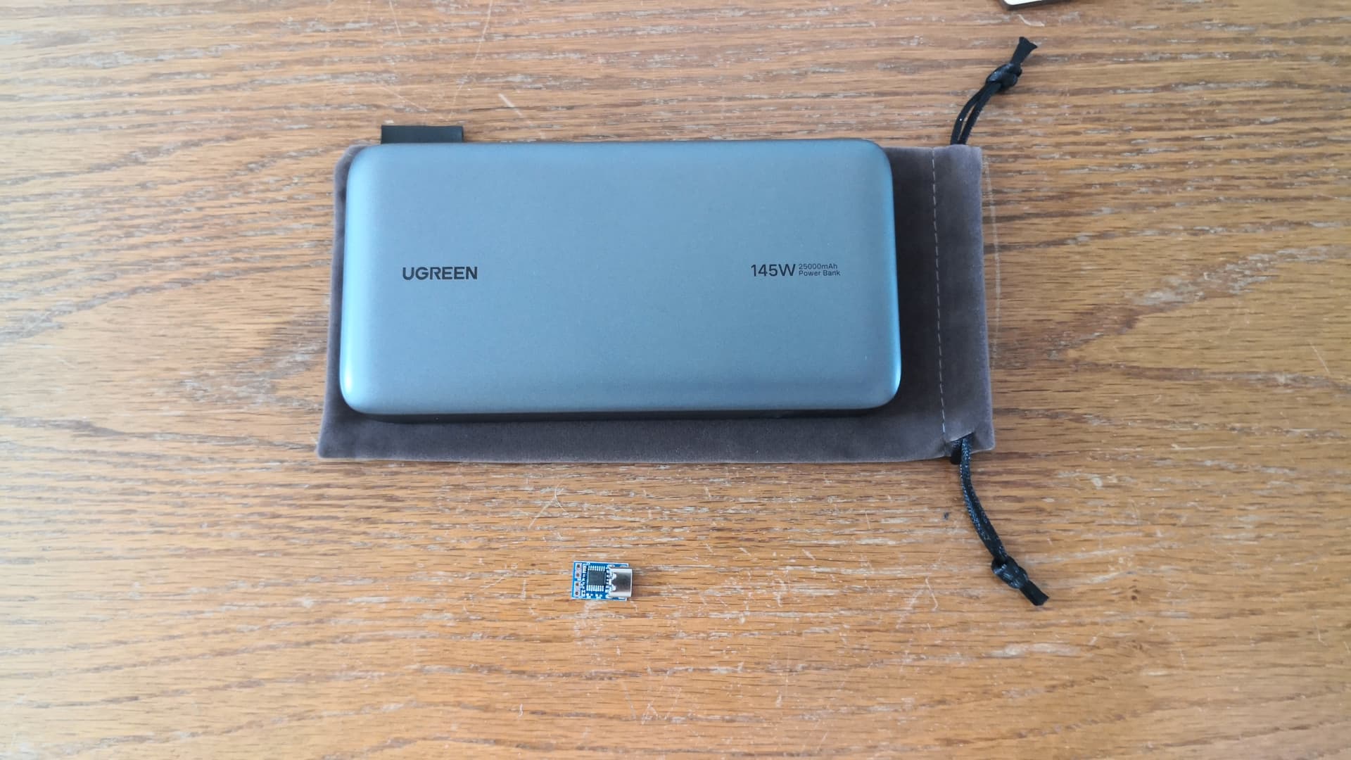
One key thing to be aware of is that the cable/MTR setup does not work with every powerbank. Some of them switch off if the load draws too little current. On receive, the MTR5b from LNR is spec’d to draw 30 ma @ 6V and 20 ma @ 12V. On my tests with a KD1JV 5b kit, the rig/12V converter cable setup was drawing an average of 60 mA from my powerbank. This was adequate to keep my Varta powerbank turned on during receive, but my larger Voltcraft powerbank turned off after just a few seconds of receive. Note that one workaround is to add a device such as the Sotabeams “USB battery pack keep-alive load” – but it’s not really practical for outdoor use.

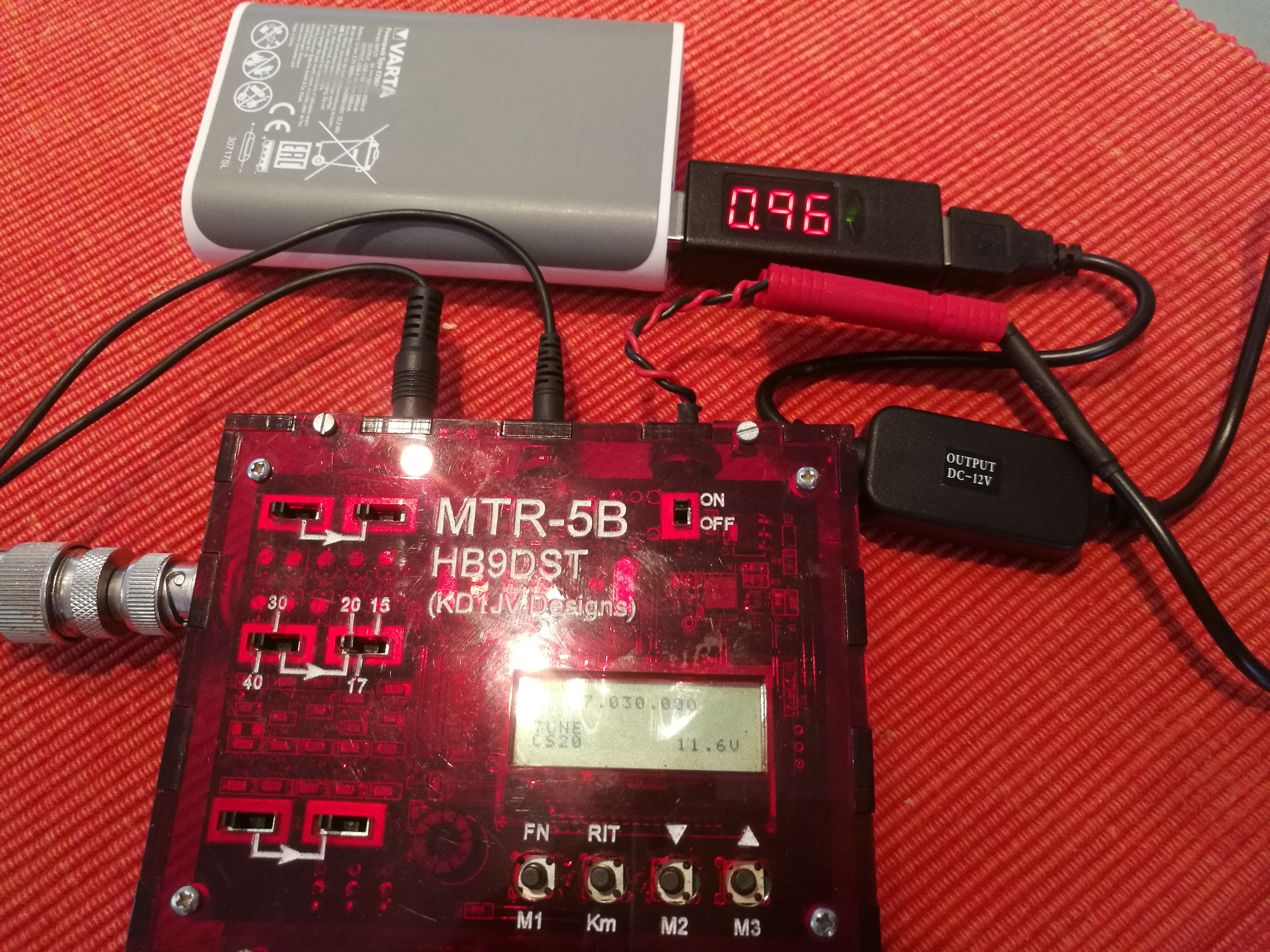
Here is a photo of my test setup with a dummy load; field trials to follow shortly. I have the MTR5b in Tune mode (continually sending a carrier into the dummy load). You can see that the MTR is detecting an input voltage of 11.6V (lower right display). The current draw in Tune mode was 0.96A (as measured with a LogiLink Model PA0067 1-Port USB power meter). I left it running for a good 15 seconds continuous.

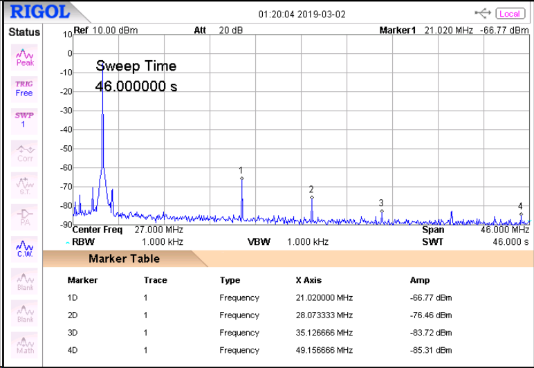
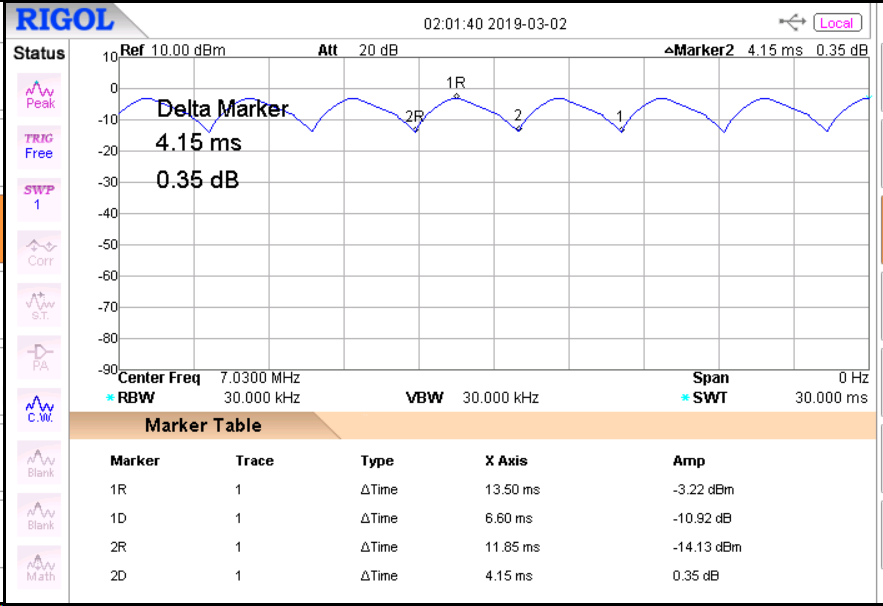
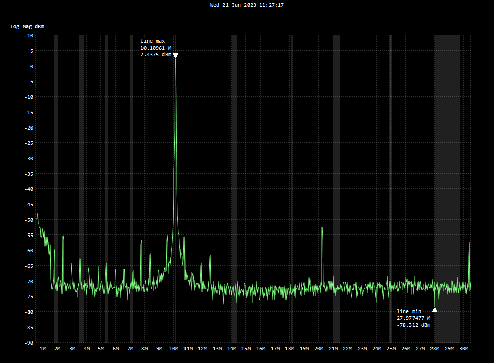
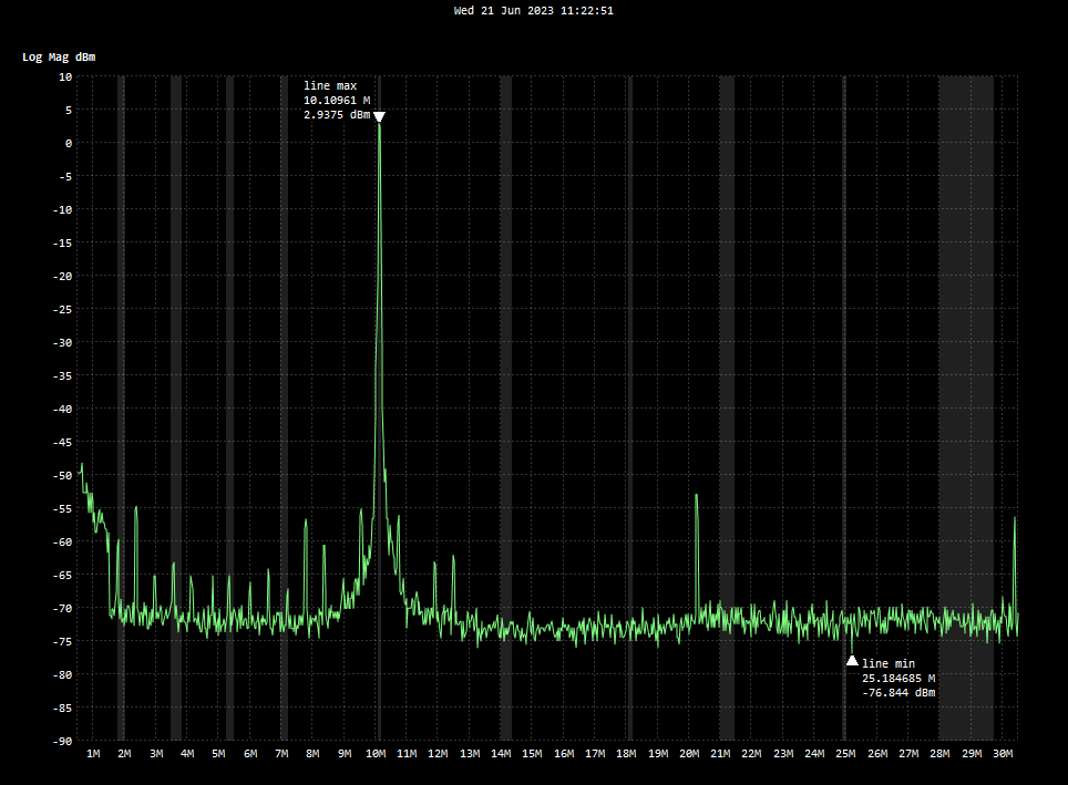
I was wondering if I would get QRM from the converter module, but there was no discernable difference in noise from the powerbank and a LiFe battery. I was also concerned about chirps in my signal, but I monitored transmission into the dummy load from my desktop xcvr and heard no difference from the powerbank to the battery.

Thus far the results are encouraging, next are the field tests. If you hear me on the air in the near future, please give me accurate signal reports (I won’t be offended if you give me a 595C).

73,
Paul HB9DST / AA1MI

1 Like

Instead of running a radio directly, these boost converter cables look like they would be useful for charging small 12V lithium packs, such as those we use in the KX2 and similar radios.

Based on Adafruit’s testing, it would take 6-8 hours to charge a 12V battery in the 2500-3000 mAH capacity range, using the boost converter cable running from a 5V power bank.

It’s not really a plug-and-play charging device, although it might work. It would be good to add metering and current limiting, so it would be a small project to make a reliable, safe charger. The voltage output looks to be just about right for a 3S lithium ion or LiPO battery. Limiting the current to 500 MA or less would be smart. With charging there’s no problem about the auto-shutoff of the 5V power bank. It would be a good feature and would terminate the charge before the battery was topped off. This is probably a good idea when charging overnight, camping, etc.

Most of the larger 5V power banks have two or more USB outputs, so it seems that you might be able to run TWO of these boost cables as chargers simultaneously, so you could charge two KX2 batteries at one sitting. The larger banks have enough energy to do this, based on the numbers available. The 5V bank would shut off once the energy is down too low - they offer self-protection from over-discharge.

Has anyone tried these boost cables for this? Or similar?

73
George
KX0R

i have a similar setup for the smaller MTR3b … i have 2x powerbank that gives out 1A max from the USB port. i originally just wired them both serially, but the powerbank turns off after a few minutes. same as your observation. MTR3b RX power draw is a measly 30mA, according to specs.

on a trip to Akihabara i bougth some DC boost boards based on the X​L​6​0​0​9 chip [Japanese warning DCDC-XL6009]. works like a charm for me. the board has an accesible VR so i adjusted the Vout to about 9.4V (this is a magic number since i have a number of Mizuho pico TRX that also want <10V). the converter also seems to be quiet in my case (i had the luxury of using cable lengths as short as possible).

73
Mela JI1KBF

1 Like

Further analysis of the “Powerbank/Adafruit voltage booster cable” approach…

Some hams have speculated that the dc/dc converter in the Adafruit cables would create spurious emissions larger than those allowed by the FCC (-43 dB). I wanted to investigate this point, but I don’t have a spectrum analyzer at home, much less a high-quality instrument. Thus, I turned to my friends at a special department at the University of Applied Sciences in Rapperswil, which also has a ham radio club HB9HSR. This department, which provides university-industry cooperation and consulting, is the Institute for Communication Systems (ICOM, www.icom.hsr.ch), and obviously has a fully equipped lab for performing radio experiments and research. Special thanks to Nicola HB9FIM who knows how to make these instruments dance – he needed just minutes for tasks that would have taken me days to figure out.

I took my MTR-5b along with a 3S LiFePo battery as well as a powerbank along with the Adafruit 9V and 12V booster cables. We used a Rigol DSA875 spectrum analyzer (9 kHz - 7.5 GHz), which accepts a maximum signal of +20 dBm. Because the MTR 5b has a max output near 5W, we added 40 dB of inline attenuation.

Test 1: Spectral purity of the MTR-5b in Tune mode when using the battery. The fundamental frequency was 7.030 with a signal level of -4.49 dBm. I was pleased to see the largest spike (at 21.020 MHz) was down 61 dB – far below the -43 dB required by FCC Part 97, Para. 97.307(d).

Test 2: Spectral purity of the MTR-5b in Tune mode using a powerbank (Varta Type 57961, 4x2500 mAh) and the Adafruit Model 2777 9V boost converter cable. Would the dc/dc booster create spurious signals? Actually, not at all – the output was just as clean as before, we could not see any noticeable difference.

Test 3: Same as Test 2 but with the Adafruit Model 2778 12V booster cable. Here we again noticed no increase in spurious emissions.

However, to our surprise we saw that the output voltage was oscillating up and down. The voltage trace under load – the attenuator – looked like the following curve where the peak-peak Tx power variation is 10.92 dB, i.e., the output power goes from 4.7 W (-3.22 dBm + 40 dB) down to 0.39 W (-14.13 dBm + 40 dB) and up again within 4.15 ms => 240 Hz.

We also examined the output of the 12V cable with an oscilloscope; unfortunately, we did not take any images. In the no-load case, we saw a sawtooth ripple voltage of approximately 100 mVpp at 142 Hz. When we loaded the booster cable with the transceiver pushing its output power into the attenuator, we saw some ripple – a combination of the slow oscillation and fast spikes from the dc-dc converter’s switching circuitry, where the spikes had a repetition rate of 1.7 MHz. These ripple components did not cause any problems because they have levels far lower than the largest existing spike at 21 MHz and they are not clearly identifiable on the spectral diagram. Even so, transmitting a signal that varies in peak amplitude by so much is not optimum – we’re not looking for amplitude modulation!

Conclusion: Powerbank/Adafruit 9V option is viable, the Adafruit 12V option is not.

3 Likes

Update/correction: 12V Adafruit booster cable also viable

After reviewing the tests I conducted, another local MTR owner brought the following to my attention (thanks, Peter):

Paul, you used Tune mode for testing – and so the ripple you observed is likely an intended feature by Steve KD1JV which is described on page 4 of the MTR-5B Manual:

NOTE: If the DC power supply exceeds 10 volts, the output power is reduced by turning the supply to the PA ON and OFF at about a 1:3 ratio. This ensures no damage to the PA if excessive SWR is encountered while adjusting the antenna tuner for lowest SWR. Since this PWM of the PA supply voltage has no feedback, the output power switches low and gradually builds until it stabilizes at about one-third its steady-state output.

This would be consistent with your observation (fine at 9V, ripple at 12V). To do ‘full power’ measurements on 12V, try setting up Straight Key mode and then do a key down. In this case the SWR protection from Tune mode is not active.

Well, based on this info about Test mode, I ran some additional tests and observed the resulting behavior on my “antique” Tek TDS210 scope.

  1. 12V Test mode – again shows the wildly varying amplitude
  2. 12V Straight Key mode – very stable amplitude

So far, so good. But I was still worried about drawing too much current from the 12V booster cable. For Straight Key mode at 12V, the USB adapter located at the powerbank output indicates 5V @ 1.21A, whereas the Adafruit device is rated for 500 mA. However, the 500 mA limit is at the booster cable’s output, not the input, according to the description on Adafruit:

50 mA (12.4V output), 150 mA, 83% efficiency
100 mA (12.4V), 290 mA in, 86% efficiency
200 mA (12.3V): 570 mA in, 86% efficiency
300 mA (12.2V): 870 mA in, 84% efficiency
500 mA (12.1V): 1500 mA in, 81% efficiency
700 mA (11.4V): 2140 mA in, 75% efficiency

Thus, if the booster draws 1.21A @ 5 V from the powerbank, we can surmise that the booster outputs approximately 400 mA @ 12.1V, which is below the 500 mA limit – great news!!

Conclusion: Both the Adafruit 9V and 12V booster cables – when used with an off-the-shelf commonly available powerbank – are viable for use with MTR series rigs.

2 Likes

I’m currently planning a longer trek with my MTR3b next year. It will be so out of the way, I’ve been looking at solar panels as a power source. The Powerfilm Lightsaver Max would be my first choice, but it’s out of stock at the moment due to the chip shortage. As it may not be back in stock before summer next year, I ordered one of these cables to play around with.
SinLoon USB to DC 5V to 12V Step Up Cable 3FT DC 5521 Power Adapter Cable with 7.9 x 5.9 mm, 3.5 x 1.35 mm, 4.0 x 1.7 mm, 5.5 x 2.5 mm, 6.3 x 3.0 mm Connectors (5 V to 12 V) https://amzn.eu/d/6GnTTx8

It has a maximum output current of 1 amp, which will be plenty for the MTR.
However, whilst looking around on the internet, I found these USB type C PD trigger cables, that utilise the newer ‘power delivery’ function of USB C to supply a range of voltages:

DSD TECH MagicConn SH-CP12A USB Type C to DC Power Cable 12V https://amzn.eu/d/jgqTrrD

I just wondered if anyone has used these successfully to power a rig? The description says it can output a maximum of 3 amps, so enough to power a KX2/3.
73 de OE6FEG
Matt

I use two methods to power from a powerbank the first is a dc-dc converter similar to the ones mentioned above

This will work with most powerbanks, but you should note that basic powerbanks max out at 10W…not enough for the ft818 but enough for most qrp rigs, such as the venus sw3b

The other option is I use is a usb-c PD cable, as you suggest:

This makes use of the usb pd protocol, which allows powerbanks to supply up to about 60W (and higher?) at voltages up to 18V (and more recently even higher). This requires a good quality powerbank and it must advertise PD capability at 12V. Even with pd comparability advertised, i have found not all power banks manage to negotiate the full advertised power

The concept of the PD cable is great, but the DC DC converter method is more reliable as it doesn’t rely on the PD protocol working

As an aside I also have a TS80 soldering iron that uses USB PD…this even gives enough power to solder PL259 connectors.

I use both of the above methods with my cw radio, an SW3B. I also use the above methods to charge my Yaesu HTs from powerbanks (and of course, works with USB mains chargers too)…very convenient.

Neither method seems to generate any spurious emissions that are a problem.

2 Likes

Just ordered, thanks very much. Yes, I noticed that not all powerbanks have the PD function. And not all supply the same amperage. Looking forward to playing around with it.
73 de Matt

I may repeat myself, but when using powerbanks or other power sources with a switch-mode DC-DC converter, it is wise to check the transmitted signal for additional unwanted emissions. The switching frequency of most circuits is between a few hundred kHz to 2+ MHz (plus harmonics) and the amplitude of ripple and noise varies greatly between brands and models (and often also by applied load/current). The PA stages of most QRP radios are more or less directly connected the input voltage and its ripple/noise, with just passive components (chokes and bypass capacitors) in between, and the frequencies are low relative to our operating frequency that the LPFs will not attenuate them.

So ‚it works with my radio‘ is typically not sufficient evidence, not very scientific, and not suitable for generalization (‚powerbanks and DC-DC converters are fine for QRP transceivers‘) :wink:.

73 de Martin, DK3IT

PS: Maybe useful link: switch mode power supply - How to filter out the switching noise from a DC/DC converter - Electrical Engineering Stack Exchange

4 Likes

Yes, thanks Martin. I have my tiny SA, and I always check the output.

 73 de Matt
1 Like

Just to add another note of caution to those above. I got my cable yesterday:

SinLoon USB to DC 5V to 12V Step Up Cable 3FT DC 5521 Power Adapter Cable with 7.9 x 5.9 mm, 3.5 x 1.35 mm, 4.0 x 1.7 mm, 5.5 x 2.5 mm, 6.3 x 3.0 mm Connectors (5 V to 12 V) https://amzn.eu/d/gHKYjrh

Naturally, I checked the voltage carefully before attempting to plug it into the MTR3b. I found that the output is 13.2V rather than the stated 12, so way too high for the MTR. Still, it does provide a more favourable voltage for the SW3B.
I must now wait for my PD USB emulator cable, to see if that provides a more suitable voltage.
73 de Matt

I think you are better off carrying a 3S lithium battery and cheap USB charger. You can get a 2 pack of 2 USB 3S chargers on Amazon for around $10 USD. I’ve been using one for a couple of years, and it has yet to fail. It says it’s for 3S LiPo batteries, but it charges my 3S 18650 packs perfectly. A 3S 18650 pack will run your MTR for a very long time. Pair with a cheap folding solar panel that has USB ports and you are all set for charging the battery and/or your phone.

2 Likes

A quick update to this discussion. I got 5 12 volt PD emulator boards for €21.56 from Amazon.

https://www.amazon.de/dp/B09GYCM5FM?psc=1&ref=ppx_yo2ov_dt_b_product_details

I plugged one into my new 25,000mAh PD powerbank and was please to find that the voltage output is 12.12V; just within limits for the MTR3b. In fact, I tested all 5 and the output was exactly the same, which is to be expected, as the board is a PD trigger and the voltage switching is done by the powerbank. When I have more time I will have a look at the output on the spectrum analyser. I also want to check the stability of the voltage, as I noticed one powerbank that a friend used had the output at 15v, but that would jump slightly on T/R switching, which would then cause an overvolts message to appear on the KX2. The solder pad board is quite useful, as it can easily be covered in some heatshrink and a diode added to drop the voltage further if need be. You might ask why I don’t just carry a 3s lipo. The main reason is that I want to be able to do everything with one battery, and that it be possible to hook the battery up to a solar panel for recharging. The recharging is more for the smartphone than the MTR3b, which would run happily all summer long off 4 18650 cells and a buck converter.

The only fly in the ointment is that the solar panel is rather heavy. I might just try to rely on the external battery pack and use the smartphone as little as possible outside of logging. I’m on the waiting list for a Lightsaver Max from Powerfilm, but that is not going to arrive in time for this summers expedition. More on that to follow.

                        73 de OE6FEG
1 Like

Well, it’s bad news for people hoping to use the PD protocol for powering their transceiver. I hooked up the MTR3b to the Tiny SA and had a look at the output. First, for control, I used a regular 3S lipo:

Next I tried the PD emulator cable that I had soldered up:

As you can see, there is barely any difference at all. The output is not the bad news. The PD emulator results in noise on the RX not the TX. Both output plugs produced some noise, but output 1 was slightly better: just a high pitched tone at around a few 1000KHz. I’m going to have to get a USB 3S charger cable and take along a small LiPo.

Oh well, nothing ventured nothing gained.

         73 de OE6FEG
                     Matt
1 Like

Thank you for sharing your results. However, wouldn’t the noise depend on the PD power source? After all, that is where the voltage conversion (if any) is happening. The trigger module is just telling the USB PD source to supply the voltage.

I didn’t notice any added noise when I powered a rig using USB PD from a Nitecore NB10000 power bank compared to directly powering via a LiPo battery, but I will try and do an A/B test some time when I am away from the city with our bad RF noise background.

73, Roy

2 Likes

Hi Roy,
yes, you’re absolutely right. Sounds like it’s just my powerbank. Bad luck for me it seems. However, I will keep the powerbank as it is very useful to me.
73 de Matt

2 Likes

The presence of rf on the lead wire is one thing.
My concern is that the up converter radiates rf energy along with the piece of cable like a dipole, which is then picked up by the antenna. I’m happy about every db of little noise at the summit and have a jammer with me.

73 Chris

3 Likes

My thoughts exactly… part of the reason we hike to remote locations is to get away from RFI. Bringing it with you makes no sense! I will stick with battery packs that provide the correct voltage. Less to go wrong and no RFI.

4 Likes