Z-tuner as a Christmas handicraft

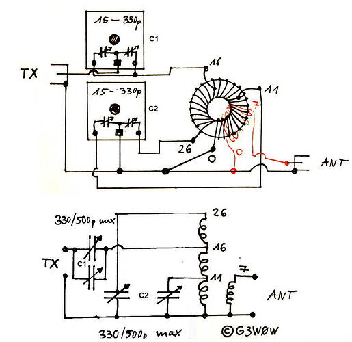
For the winter evenings, I would like to suggest tinkering with a qrp antenna tuner.

What do you need for that?
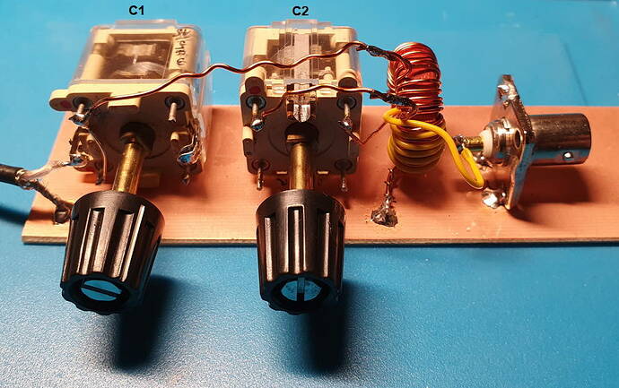
2 small variable capacitors from old transistor radios with rotary knobs
1 Amidon toroidal core T2-100 or slightly smaller or larger
2 BNC sockets
enamelled copper wire 0.2-0.5 mm diameter and isolated wire

The variable capacitors usually have 6 connections for AM and FM superhets. Use the one with the high capacity, try it out if necessary. At C1 the 2 stators are connected.

The tuner works from 80m to 10m up to approx. 10W. Reduce the power to tune. With the Yaesu FT-817, I switch to AM with a maximum of 1.25W and press the PTT.

The attitude is sensitive and you need a little patience.
First put C1 in the middle position.
Then find the minimum SWR value with C2. There can be two minima.
Then change C1 and C2 down to the smallest SWR

I was able to use it to tune my 20m long EFHW (40m/20m/15m/10m) in addition to the 1:49 transformer to 80m, 60m and 30m as well.

Have a nice day and - if we don’t meet on the band beforehand - a happy and healthy New Year.

73 Chris


11 Likes

Add a small switch on the earth side of the secondary coil and a pair of banana plug sockets, one each side of the secondary, and you have a matcher suitable for both balanced and unbalanced antennas.

3 Likes

like here:

73 Armin

2 Likes

The ZM4 is a good tuner, but sometimes has problems with the switches.
Too many error prone switches :slight_smile:

the less switches… the better the approach…

73s
Ingo

2 Likes

Manual tuners are very personal. Depending on how you operate, with various antennas, tuners can take many forms. The more you know about your system, the more effective a particular tuner can be.

Switches give you options to match a variety of impedances, across many frequencies. If you understand your tuner, and build it yourself, the advantages of switches are obvious. Certainly too many switches can be confusing, and they may lead to bad matches, without knowledge of their function. If you have too many variables in a system, there may be unexpected consequences.

The ZM4 is somewhat similar to the ZM2 and the USA version of the BLT. The ZM4 is a true Z-match, using a double variable tuning capacitor, attached to different taps on the tuning inductor. Z-match circuits that tune two or more frequency ranges have been around since the 1940’s or earlier. They are useful, they sometimes are miraculous, but they are not very intuitive. Their functioning is complex, especially with reactive loads or high-Z loads. They can be very effective also!

I have found three main problems with the manual tuners I have used:

  1. Unwanted resonances at certain settings
  2. Common mode matches when a balanced match is desired for balanced lines
  3. Loss when feeding very high or very low impedances

Unwanted resonances usually cause loss and lead to incorrect settings, with little power going to the antenna. You can often find them using an analyzer connected to the input of your tuner, using very low power. Connect no load to the tuner, or a short circuit, and you can still find a match or matches at incorrect settings. These are caused by unwanted coupling, inevitable series resonances, and other parasitic behavior among the components. They often occur when trying to match a high-Z load near, or above, the upper frequency limit of a tuner.

Common mode matches occur with the BLT tuners, and probably with the Z-Match tuners. When feeding an antenna with balanced line, especially when the feedpoint has a high impedance or a very reactive impedance, an additional matched tuning occurs, usually at unexpected settings. This is because the tuner is matching the feedline and antenna as an end-fed system, with both sides of the transmission line IN PHASE. This may occur more easily if the IN PHASE impedance is easier for the tuner to match in common mode, than to match the feedline in balanced, push-pull mode. The common mode feed relies on stray capacitance to ground, as well as unwanted coupling within the tuner, spurious resonances, etc. The radio may see 50 ohms at the tuner connection, and the antenna may well radiate effectively. The antenna has become a T antenna, effectively single-wire fed, with both sides of the feedline more or less in phase. It’s really a top-loaded vertical system. Usually when this occurs, the operator either doesn’t know it’s happening, or he fails to understand it. He may know it’s not the normal match, because the tuner settings are different from what’s expected, or the adjustment of the tuning is very critical. Beware of sharp tuning!

Significant tuner loss is often caused by using a design that is not appropriate for the impedances involved. Often this is because the taps on the the main inductor are not quite right, or because the secondary circuit has too few or too many turns for an optimum match. This is almost inevitable when using a single antenna or wire on many bands. Switches or manual taps may be needed!

It is likely that autotuners have similar issues, and often the operator would not realize there was a problem, as long as there is a match for the radio.

In my experience, the Z-match and BLT-type tuners are very useful and wonderful, but they may not be ideal for feeding high-Z end-fed antennas, like the 20M wires we use for SOTA on 40-20-15M and other bands. The simple tuners I use and have described are easier to tune with fewer issues, and probably have less loss when feeding impedances above 1000-2000 ohms.

Using tuners and making contacts is a lot of fun, and there is much to be learned by experimenting and trying new tricks!

73
KX0R
George
14 Likes

Thanks George for your insights about tuners. :+1:

Cheers, Geoff vk3sq

In my opinion, the tuner always belongs at the feed point of the antenna. I consider everything after the tuner as an antenna.
That’s the beauty of SOTA. As a rule, you sit next to the feed point and therefore such tuners, as Chris @DL1CR has presented here, also work wonderfully.

73 Armin

2 Likes

Yes I agree with you George. In my successful attempts with the 20m long EFHW, the 1:49 transformer was connected between the antenna and the tuner.

At 3.5, 5.3 and 10.1 MHz the wire is 1/4, 1/3 and 2/3 wavelengths respectively. And the impedance is less than the approx. 3kOhm at 7, 14, 21, … MHz with significant capacitive or inductive components. In addition, there is the loss resistance of the non-optimal counterweight. The 1:49 unun transforms this total impedance into ranges that the tuner can adjust.

With my KX2 tuner it works without any problems and with amazing success even on 80m (Phil, G4OBK, 729km, 10W, CW, 1330utc) . The z tuner should do it the same way.

73 Chris

5 Likes

A good idea, perhaps also to be realized for the less technically experienced Ham.
73
Paul

3 Likes

I had some problems using the delivered switches and replaced this parts two years ago by ones with a different quality. It’s described here (sorry, only in German).

The problems were gone and don’t came back until now.

73, Ludwig

3 Likes

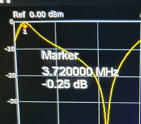
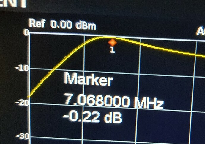
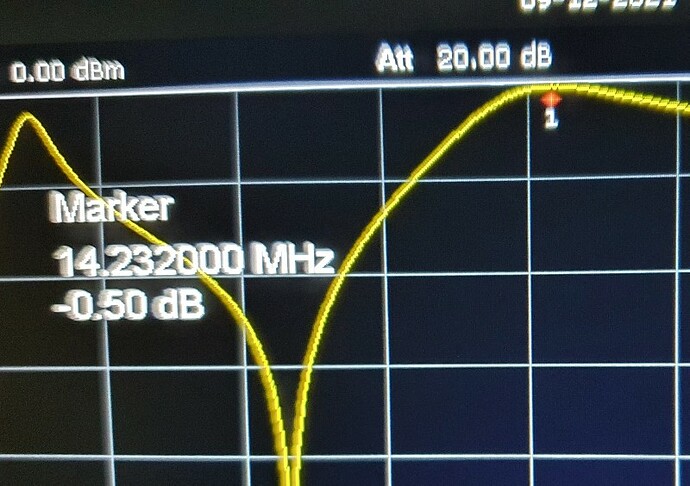
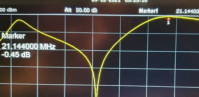
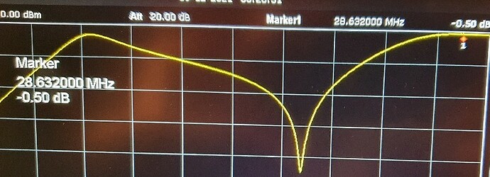
Tonight I quickly measured the attenuation at 50Ohm of the z-tuner. On the bands 80 to 10m the value is below 0.6db and is negligible.

73


2 Likes

Hi Chris,

Thanks for these, very interesting :slight_smile: I’m assuming this is 50 ohm in and out, ie no transformation of impedance? Have you tried with any other load impedances? (Not a trivial exercise in my experience :frowning: )

73 Paul G4MD

1 Like

I will do it tomorrow. Today I was able to test the z-tuner for the first time at a summit. Here is my report
https://youtu.be/s8Vp6Ssbed8

The contact to a 9A station at 80m was particularly surprising.

73 Chris

3 Likes

For those who care.

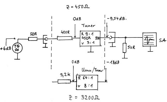
The attenuation measurement at different impedances is done with the help of appropriate resistors.

Example 1
Measurement of the tuner with input impedance of 450 ohms and output impedance 50 ohms

The tracking oscillator of the spectrum analyzer is set to 0dbm. + 6dbm are generated internally and 50Ohm applied, so that with the usual 50Ohm terminating resistor, the output voltage is 0dbm.

Due to the external resistance 400 ohms, there are also 0dbm at the 450 ohms tuner input. The tuner transforms the 450 ohms to 50 ohms (1/9) with -9.54 db (1/3 gain). Assuming lossless transformation -9.54db should be present at the RF input.

With my Z-Tuner I measure from 3.5 to 30MHz -10db to -11db resulting in a 0.5db to 1.5db loss.

Example 2
Measurement of my 1:64 ununs with input impedance of 3.2kOhm and output impedance 50Ohm

External resistance 3.2kOhm, unun input again 0dbm, transformation from 3.2kOhm to 50Ohm (1:64) with -18db (1/8) RF input -18db

Measurement 3.5 to 30MHz -19.8db, resulting in a 1.8db loss . This coincides with previous measurements

73 Chris

4 Likes

Thanks for this Chris interesting method will work through it and try myself! My previous efforts have been based on using transformers to provide the higher impedance load which proved to be very problematic and produced inconsistent results.

73 Paul G4MD

Addendum
The Z-Tuner can also be used directly on the EFHW, i.e. without Unun, but the losses are significantly greater, as George KX0R has already mentioned.
That’s why I didn’t follow that. I think it was -3db at 7Mhz, - 6db at 14Mhz.
I should be much better with more output windings. (Do you say so?)

1 Like

Paul, I have had the same experience.
By the way, I usually use 1 / 4W carbon film resistors

73 Chris

2 Likes

Thanks Chris glad it’s not just me :rofl:

I’ve found paralleled 0.6W metal film resistors to be very good for QRP dummy loads up to 2m despite the (theoretical?) inductance due to the spiral track involved.

73 Paul G4MD

2 Likes

Yes, works fine including 2m.
I tried to find out how big the inductance of these resistors is. I did not find anything in the data sheets.
I’ll do a test with a spectrum analyzer tomorrow.

2 Likes