Today we used our CW tube transmitter for the first time on a summit.
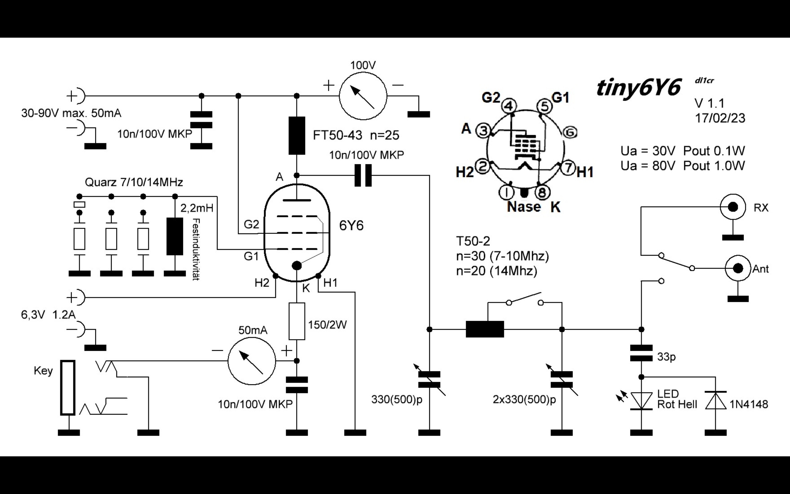
I developed the crystal-controlled 1W transmitter for 40, 30 and 20m and Uwe, DK8OA built it in an exemplary manner. A Lipo battery for the filament and 10 standard 9V batteries served as the power supply.
A Swedish straight key was used, which Lars, SA4BLM had given me as a gift.
Although the conditions didn’t play along, the spots on 20m and 40m were successful. Switching from transmission to reception, which used in early 20-50th and the unusual straight key demanded a lot from us. Nevertheless, even an S2S call gets between the chasers.
It was great fun and will definitely be repeated. Now I will develop the appropriate receiver. Uwe is already waiting for the circuit diagram
TNX to ON6ZQ, HB9AGH, OE8TIR, HB9FAB/S S2S on 40m and EA7GV, HB9AFI/P S2S, EI6FI, OE6FEG/P S2S, IK2LEY on 20m.
Very cool! I love tube stuff. I wonder how long those 9 volt batteries
will hold up though. We used 6Y6 tubes in the telegraph industry for switching
because they ran on low anode voltage!
73,
John, K6YK
The schematic diagram brought back memories of my early days as SWL. My first SW-RX was a home made tube 0-V-1. An aluminium baking tray was the source for the chassis. Long time ago.
If I remember correctly, there used to be mechanical oscillators (think electromagnet opening its own supply switch) that generate a 200 Hz square wave, to be voltage-transformed to 200-300V with a transformer, then rectified with a Graetz circuit, for producing the anode voltages for tube circuits back in time - like for the Paraset. So maybe a mechanical boost converter would be the gold standard for authenticity .
73 de Martin, DK3IT
Good stuff, Chris…and memories galore! Nice building display as well.
How times have changed; compare a 1N4007 diode (1,000V, 1 Amp) diode with an 0Z4 valve (typical auto radio rectifier) Then, along came synchronous vibrators, so no rectifier needed! I can still remember the hum…
Vibrators are available everywhere. All those I have seen are 6 volt. The last one I owned was in a Ford, and it was balky. It started every time when I slammed the door after turning on the radio.
Great fun, Heinz!
We spent a good part of the last century getting the lowest possible distortion. Western Electric 300B amplifiers, Partridge transformers, etc.
Then, after rock-n-roll, trying to emulate the sound of over-driven guitar amplifiers: big distortion, breaking up, FUZZ, etc. Warm and fuzzy will never mean the same thing!
Ken
Here is one circuit of the Paraset from the Google Groups “Paraset Builders”
The transmitter is pretty basic and works well enough but the two valve receiver is something of a tuneing horror. Unstable and was orginally intended to cover from about 2.5 MHz to 8MHz which makes for a very cramped and finicky tuneing.
I wound plug in coils for both 40 and 80 metres which made things a lot better.
In my SWL days I built a copy of the paraset receiver. The reaction was very finicky, and I found that I got better results by having an RF stage and dispensing with the AF amplifier, the audio into high impedence headphones was quite adequate, and in wartime conditions it would have prevented the radiation that the enemy could detect.
Here’s a little power supply you can duplicate or maybe find one at a swapmeet.
It’s a Heathkit GP-11. Puts out about 250-300 volts at around 100 Ma or so with 12 or 6 volt input. Quite small and light. It’ll make a little transmitter put out a few watts. It was made
for the Heathkit HW-29, HW-30, etc.