You’ll note that the secondary and primary share a common ground connection.
It seems to me that this galvanic connection between primary and secondary is an invitation to common mode interference on the antenna feedline.
If we connected the counterpoise only to the ground of the secondary, and had no galvanic connection between primary and secondary, wouldn’t that solve the common mode interference issues that plague these (and so many other) antenna designs?
Why do we build these transformers with a galvanic connection between primary and secondary?
Perhaps in QRP EFHW antennas, common-mode interference is not a major concern. By connecting the primary and secondary windings, the coaxial cable shield can serve as an effective counterpoise.
If the primary and secondary are not connected, an additional wire must be attached to the secondary ground to provide a separate RF return path (counterpoise).
… unfortunately, this is wishful thinking, because converting large impedance ratios inevitably also generates common-mode currents, even with the most exemplary implementation …
Like Andy I wind my antenna matching ratio transformers with isolated windings and fed at 5% of wave length from the end specifically to minimise CM current.
They are not baluns.
If you want DC isolation for a 1:1 unun it needs to be wired as a 1:1 transformer. It will have a reduced bandwidth cf a length of coax wound on a core.
I read this thread with interest. I have been a link dipole man, fed at the centre via a current balun all of my Sota life. I saw no advantage in using an end fed.
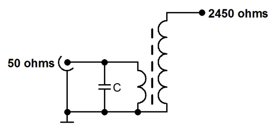
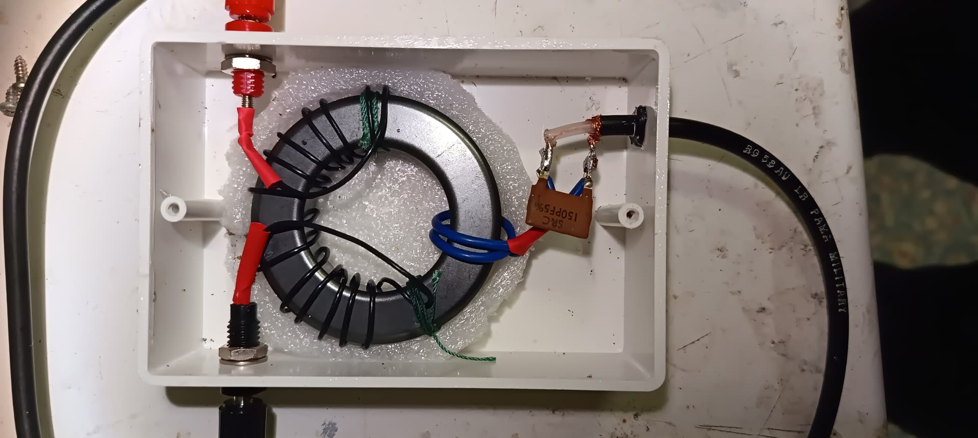
Then a few weeks ago I needed an HF aerial in my daughters garden in Germany. Due to the shape of the garden I decided to give an endfed a try. This coniguration would place the high current part at the middle of the aerial 6m above ground. A trawl of the web found examples of the UN-UN winding matching unit to be popular, but this configuration is widely reported to be plagued with common mode feedback. I decided to go back to basics. Yes the impedance as Ron says is in the order of 2500Ohms about 1m from the end of a 7MHz halfwave. I could visualise the required matching unit. A transformer was needed to match 50Ohms to 2500Ohms. This was achieved with a 2 turn primary and 14 Turn secondary. The windings were separated to avoid capacitive coupling. The dipole is DC isolated from earth and feeder. At 100W input about 500Vrms and 200mArms being generated in the transformer secondary. It was then that I realised that the commonly used term “Counterpoise” was misleading. The 1m of wire I had fitted after the coil was simply the last bit of the resonant aerial. Without it the coil current has no where to go! I followed the guidance of others, (probably over engineering the core for 100W), by using an FT240-43 ferrite core. The LT winding is simply 2 turns of pvc insulated wire, The HV winding is 14 turns of silver plated PTFE instrument wire (‘cos I had it). On the bench I tried it out using an analyser and a 2500Ohm carbon resistor load. The match was close to 1:1. Again following the work of others I connected a 150pF siver mica capacitor to the LT terminals. Using the analyser this indeed improved the match above 20MHz. I mounted the matching transformer on my 6 m Glass fibre mast about 2 m above ground. The total length of aerial wire being about 19m.
During field trials I easily achieved SWR of 1:1 on 7 MHz and 1.5:1 on 14MHz. The match at 21MHz was 2.5:1 and rubish elsewhere (a good sign). Running 100W I had no evidence of common mode feedback to the rig. Taking hold of the feeder did not affect the SWR, another good sign.
I thought a balun was any type of balanced-to-unbalanced transformer or choke?
In this case I suppose it is an unun, since both antenna and feedline are unbalanced.
You are saying that DC isolation results in reduced bandwidth? Is that why all of these transformers (balun, unun, EFHW, etc) are usually wound with common ground, to increase bandwidth?
Of course there is some leakage capacitance between primary and secondary. And you will get some common mode current due to near field effects. But if you eliminate the galvanic connection and provide a proper counterpoise, I do not understand why significant common mode current would flow. Near field effects are a separate issue and can only be solved with ferrite beads, as far as I know.
And that works fine? Good to know, then I will try it with the next one. Maybe I will add a jumper to optionally connect the common ground, for when I do not want to bother with a counterpoise wire.
An EFHW always requires a counterpoise, contrary to what many believe. With an EFHW, the coax will ALWAYS serve as counterpoise unless you connect your own separate counterpoise.
Without a dedicated counterpoise, the feedline must be the correct length (approx 2m for a 20 meter long wire, if memory serves) to get good performance from the antenna. And you should put some ferrites on the coax just before the radio to keep common mode currents entering the radio.
So yes without the connection between primary and secondary, a counterpoise is necessary.
But, even with a proper counterpoise, common mode currents can be an issue, especially once you get bit above QRP power levels.
That sounds very poor on the higher bands. I’d expect 1:1 on 14m and 21m and 2:1 on 17m from any of my EF40mHW. Intetested to know if you have put a VNA on it to see where the full-wave & 1.5-wave resonant frequencies fall? If so, does the absence of useful frequencies on the multiples result from the different transformer configuration? Like you I use a 150pF cap across the input, but a 8:1 coil ratio (64:1 transformer) with common ground & no counterpoise other than the coax.
Indeed. Even RF current has to flow somewhere. Nobody expects a torch (flashlight) lamp to light up if one wire is disconnected from the power source. And the antenna works by creating fields, magnetic and electrostatic, between the two halves of the antenna.
It is not an end fed antenna at all, it’s an off centre fed half wave antenna. the total length from the 1m wire end to the other end of the half wave, is a half wave, minus an allowance for “end effect” as in any dipole with ends, usually around 5% depending on wire thickness and wavelength.
The omission of the last metre of antenna is sometimes compensated for by using the outer conductor of a coaxial feedline as the missing piece of the antenna, with a choke at the appropriate 1m point, or wherever resonates the antenna. Hence the non resonant end fed wire with a “counterpoise” floating around the transformer to produce the right swr. ie. to resonate the wire labelled “antenna” with the wire labelled “first metre of feedline”.
Galvanic connections are a good idea to allow discharge of static charge that builds up on wires. A 1 Mohm resistor in lieu of a copper link will be satisfactory and have very little effect on antenna balance. Antennas on a mountain in a breeze on a dry day can build up many kV and give you a nasty whack if you touch the wire.
If you treat an unun as a black box it doesn’t matter how it is achieved, at the design centre frequency. The bandwidth is usually greater for a transmission line device than for a conventional transformer. So a 1:1 RF transformer will have less bandwidth than an optimised coil of coax but be galvanically isolated. This transformer is sometimes called a braid breaker. It was popular for minimising tvi back in the analogy tv days when feedlines were hf antennas in disguise.
Mostly when dealing with antenna we want a current balun or a transformer with the secondary floating and not grounded. See remark about static charges.
Using the coax as part of the antenna without a ferrite isolator is agricultural and poor cheapskate engineering. It is sadly common with the perpetrators loudly proclaiming how good it is.
What you describe is exactly what I was getting at. By building the transformer with no DC connection between primary and secondary, the EFHW becomes a pure off-center-fed dipole. I think the “counterpoise” section plays the role of a “capacitative hat” – one could probably replace it with a suitable construction.
Anyway, if the EFHW transformer works fine (as I suspected) with no DC connection between primary and secondary, why not build the baluns used for center-fed dipoles this way as well?
Maybe I missed a section of the antenna handbook, but none the dipole baluns I’ve seen had DC isolation between feedline and antenna.
I see. And the battery-powered radio sitting on bone-dry sand has enough conductance to earth to dissipate the charge coming down the cable?
Okay, now we’re getting somewhere. But the “ugly balun,” “stack of ferrite beads on the coax shield,” or “RG-316 wrapped around an FT240-43 core” approaches have clear and obvious reasons why they have wider bandwidth.
My question was specifically about building the RF transformer with or without a galvanic connection between primary and secondary. Does that galvanic connection also affect bandwidth?
Agreed. But with a battery powered radio doing 5W and the correct length of feedline, it works well enough to get beginners on the air, so I’m not complaining too loudly. It’s a more sophisticated version of the “agricultural dipole” consisting of two wires approximately cut to length, and a BNC to binding post adapter.
I will say that I have been surprised at how much commercial antennas and accessories can under-perform. I’ve seen commercial EFHW antenna couplers (1:49) rated for 50W that get noticeably warm at 5W, or rather expensive portable antennas that only work properly if you use them with a QRP radio AND an ATU.
My DIY EFHW coupler, made with an SMA jack, and carried with a 2m length of RG-316 cable (terminated with SMA plugs), has, on the other hand, proven to be not just bulletproof, but also far smaller and lighter than any commercial solution.
A 1 Mohm bleed resistor won’t have any measurable effect on the antenna or the matching. Did you think it would be a problem?
Well obviously there needs to be some conductivity into the ground to bleed the static charge. Anything below a few megohms will be fine.
I used to carry a steel tent peg with a flexible lead to connect to the ground lug on the FT817. However few of my activations are in such dry nonconducting places as you envisage so I haven’t bothered with the earthing.for a long while. My judgement might be faulty. I’m sure you would be a better judge of the risk.
The last time I strung up a wire in such conditions (high altitude, bone dry conditions – literally a desert at 4000m altitude) I had zero issue with static buildup.
Probably there is or was some mitigating factor bleeding off charge regardless of the fact that there was no good earth connection within sight.
But adding a 1-10 MOhm resistor across the transformer can’t hurt either way!
It is a long time since I delved into transformer theory, but I seem to remember transformer inductace as L1+L2 +2M (please correct this formula as necessary), where M is the mutual inductance between the windings. I suspect that with the transformer windings I have used it will not provide the broad band performance we would expect from Bi or Tri filar close coupled windings. I suggest that for my transformer to work effectively on the upper HF bands a different core would be needed, but that is not my interest. I am satisfied with a useful performance on 7MHz to 14MHz and 21MHz.
As a consequence of this discussion however I am considering installing a link to enable the aerial to resonate on 10MHz when required.
Well, even if you still consider it sporty to conceal your identity on the SOTA Reflector, here’s a hint about a few things.
As correctly mentioned in the thread, from a physical point of view, no current can flow in a single wire that is open at the end. The term EndFedHalveWave (EFHW) Antenna is therefore misleading
When this so-called EFHW antenna is completed with a 2nd leg (part of the half-wavelength!), an ExtremelyOff-CenterFed (EOCF) half-wave antenna is created
When the feed point is moved from the center of a dipole (differential-mode current in both legs ~equal, common-mode current ~0) to one end, the common-mode current increases continuously, at the expense of the differential-mode current in the shorter leg (due to the significantly different impedance at the feed point of the two antenna legs).
Rick, DJ0IP, an old OCFD expert, explains in detail the CMC problem typical for OCFD antennas (and of course also for EOCF) antennas The Hitchhiker’s Guide to OCFD