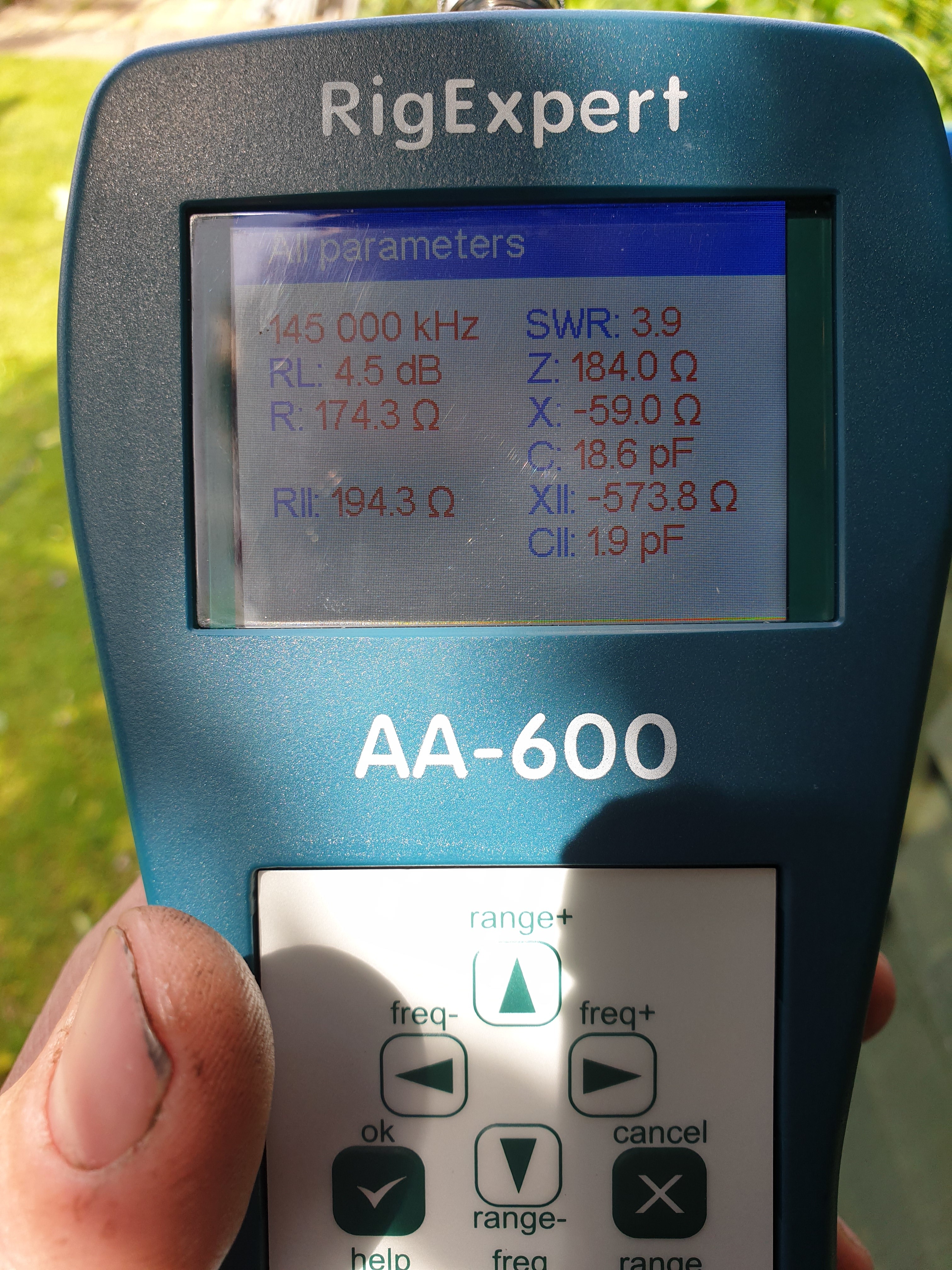
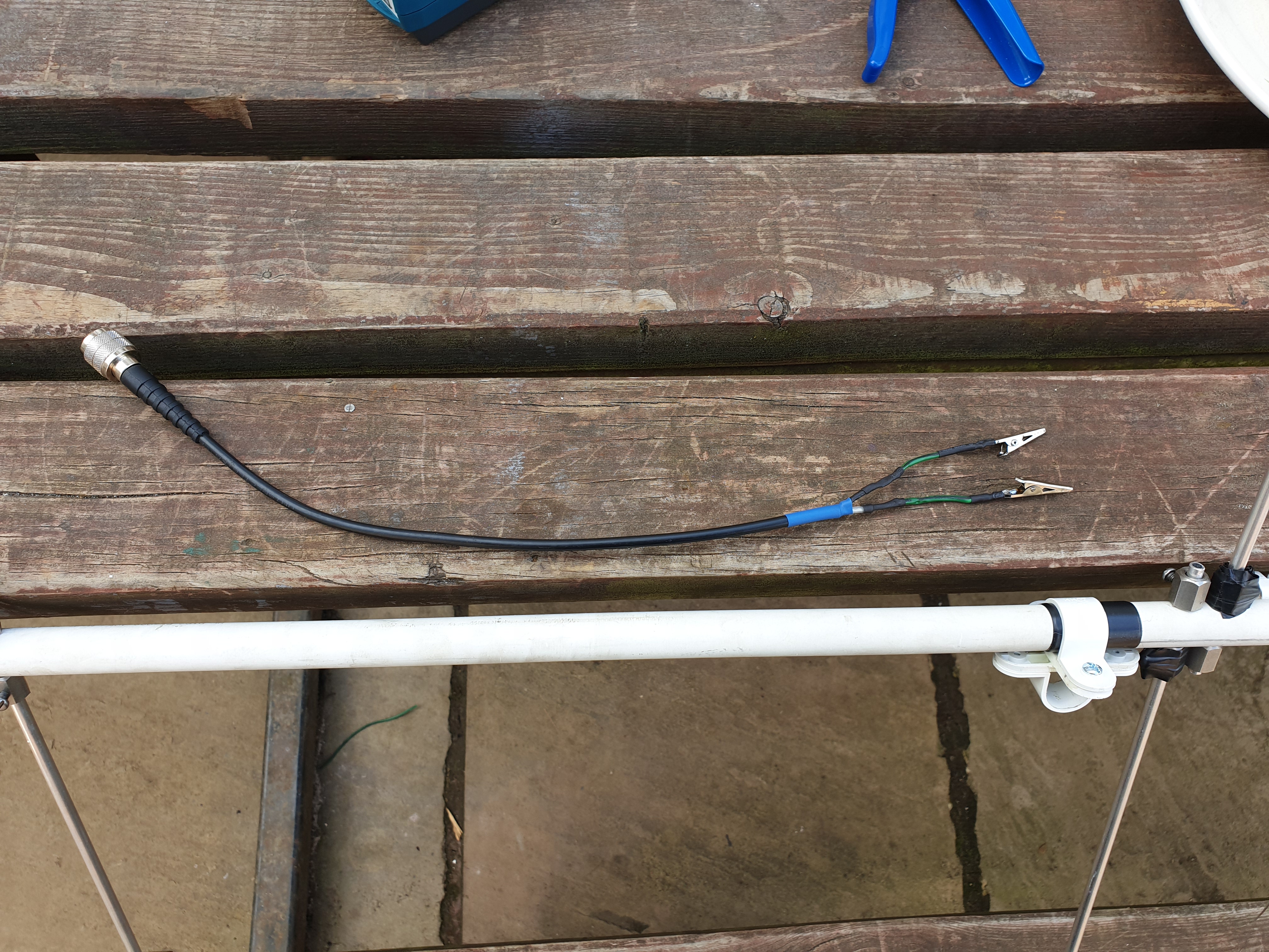
At the moment i have a rig expert analyser but the results are still sky high . Took it apart re measured assembled it again and still the same . 3 coax leads 2 with bananna plugs other with croc clips and tested with meter and no shorts . But still high …
We need to know what the resistance and reactance readings are before we can be truly helpful.
However, just looking at the pictures, it appears the only thing standing between you and success is a simple piece of wire bent into a simple hairpin match. Look up the feedpoint scheme on a tape measure yagi and duplicate that. I bet you get the feedpoint match down to near perfect with a hairpin match.
Looking at the original article, I don’t think there are any figures given for SWR. It may not have been tested in that way.
There is also the comment “The reflector should be 40" - you can add a stub of aluminium rod to make this length up if you wish, I just ignored it, and left it at the 1m length as it came”.
Which doesn’t speak of great attention to detail
Roger (original builder) says that it works, and I’m sure he is right - it will have transmitted and received - but that in itself doesn’t prove that it provided a good match.
Like this:
However, I would be wary of trying to make a “mix and match antenna” using dimensions from different designs.
The hairpin will only work properly if the dipole is the correct length, and spaced from the other elements so that it presents a certain impedance at the centre. It isn’t there to mask inaccuracies in the design.
I wonder if the Antenna Analyser is being fooled by either common mode signals on the coax or actual RF being fed into it. I had a lot of problems tuning a big 70 cm antenna when all the analysers showed rubbish results - RF pickup. Testing it using my Bird Thruline and it tuned up perfectly.
Get well away from the antenna (but then coax loss might fool you unless it is really low loss) or, my preferred option, get some sort of choke balun close to the antenna to get rid of common mode signals but, whatever you do, make sure you and the test gear are well away from the radiated field from the Yagi to keep radiated RF out of the test gear.
Have you ever tested another VHF antenna with this device? Can you be sure that it works?
What is the SWR at lower frequencies? If it is better then you can cut the driven elements.
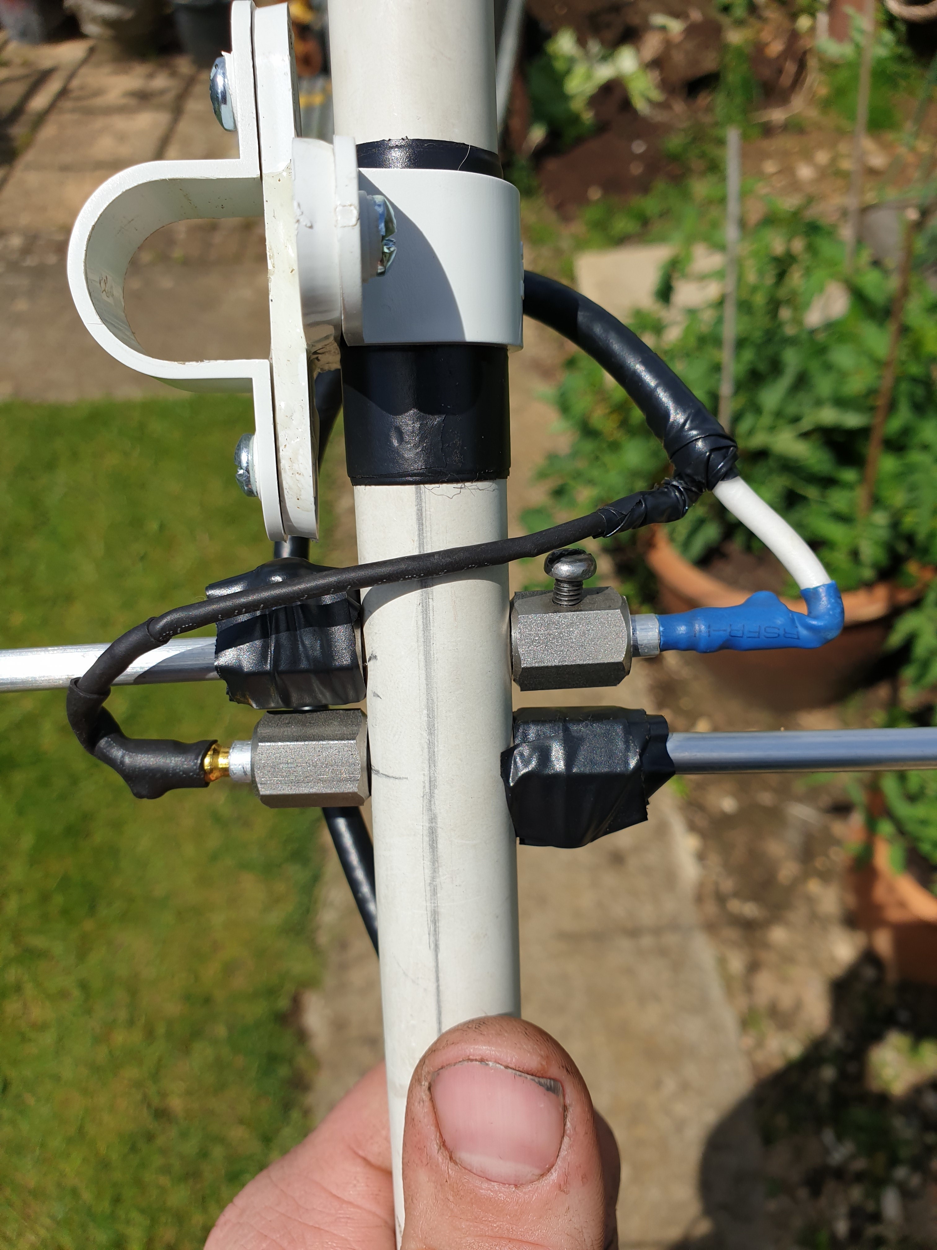
I suggest those connecting wires are part of the problem. On 2m such wires should be about half an inch. Those in the picture look like 4 inches. Those wires would be detuning the driven element. At that length they have to be considered part of the antenna.
In addition, the long overlapping sections of the driven element would be affecting the resonance. I would think an overlap of an inch, max, would be ok but would still detune the driven element. For the length of the overlap, equal and opposite currents are flowing in those elements so that length is cancelling out, effectively shortening the driven element, hence the negative reactance.
There are many simpler ways to improve on the stubby helical.
I have followed the design and i couldn’t mske the wires any shorter to plug in with banana plugs they just plug in if the other side is plugged in . And the design has a overlap , the only thing j could do as the croc clip idea was a fail is to make another long lead with equal tails .
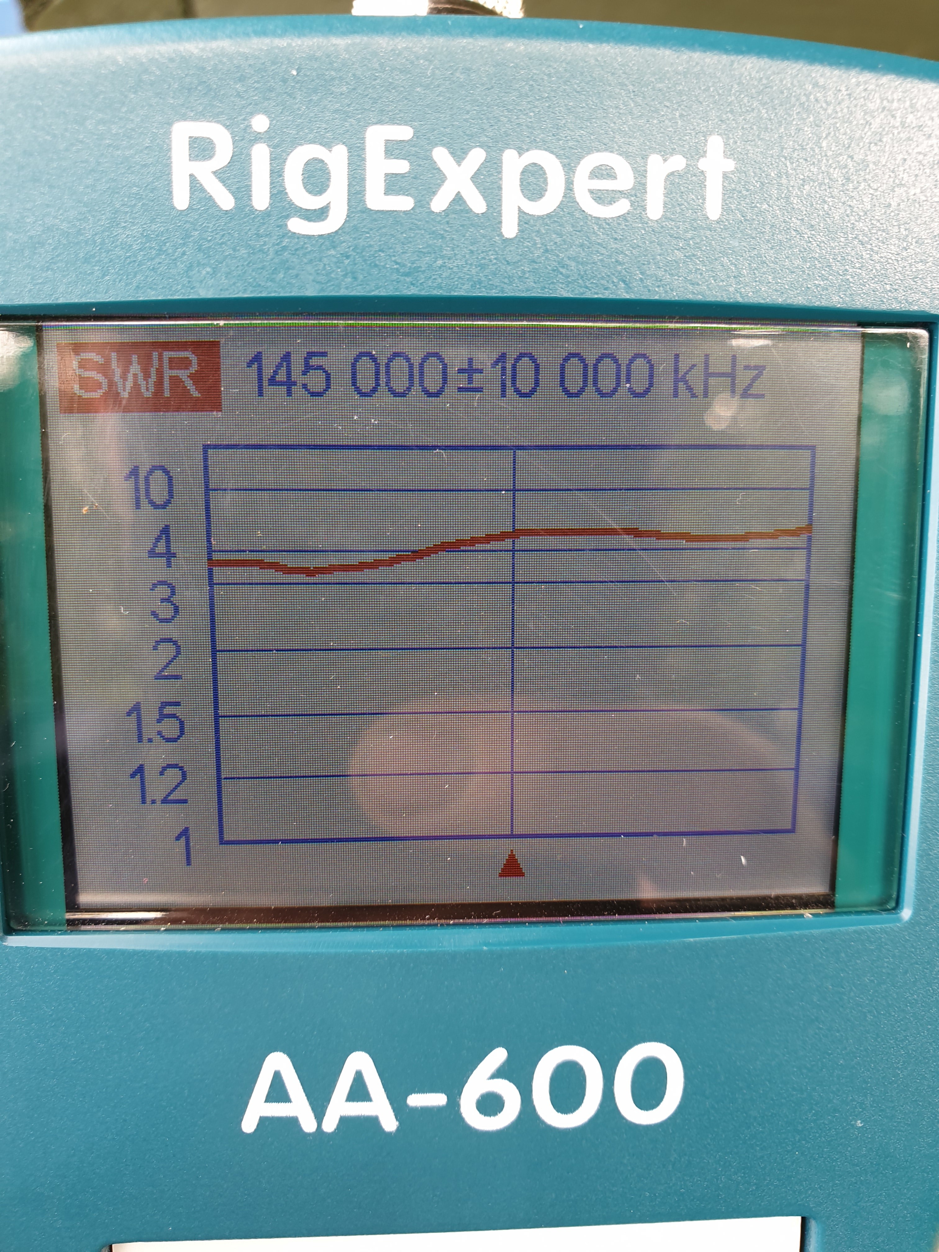
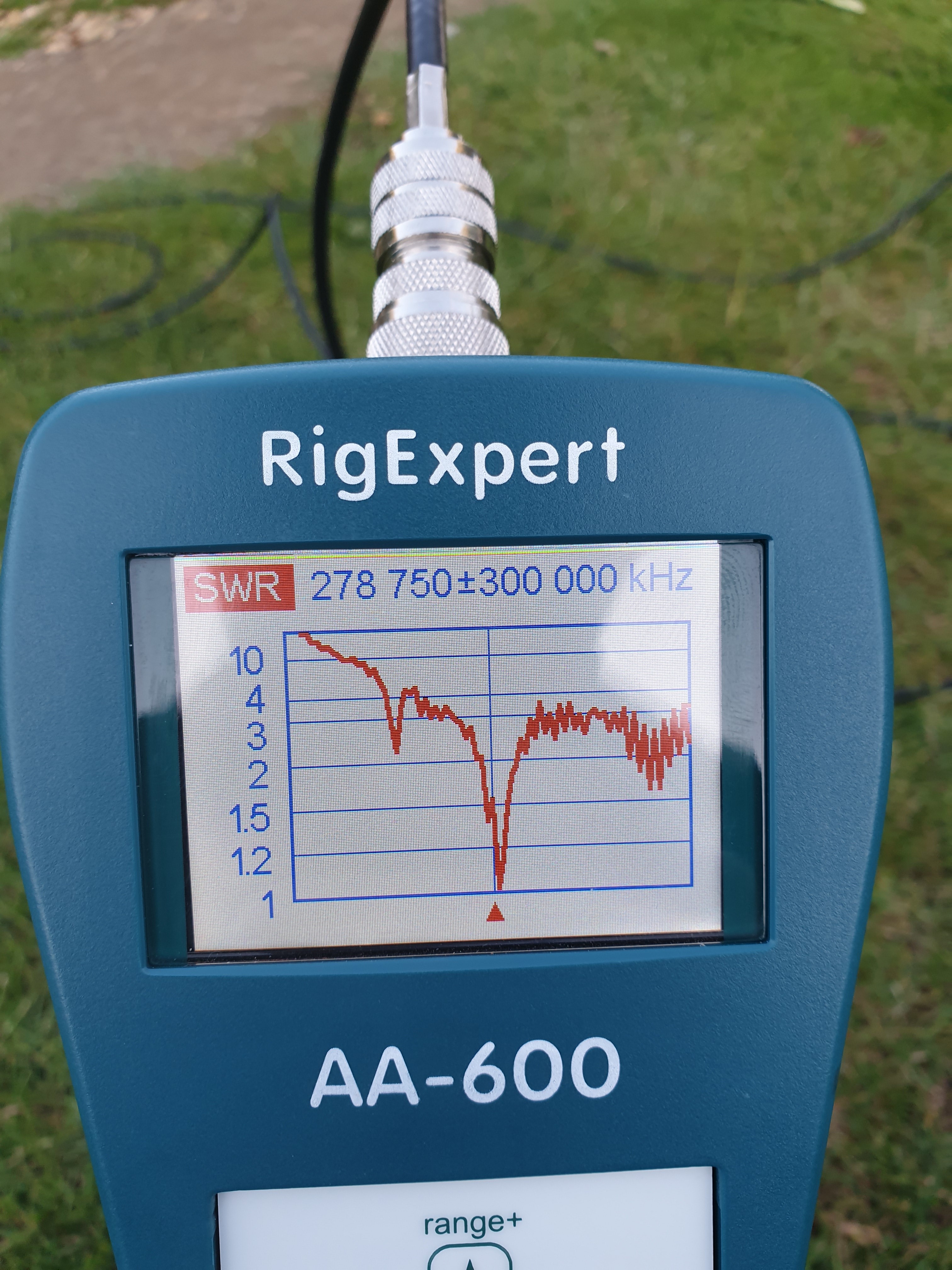
I had another play with analyser and found 2 dips in swr sweep .
Even though the elements are the corect length and as short overlap as i can get and the same size tube its still looks like i can still improve by moving the 2.1 resonant point which is obviously better than what i have now .
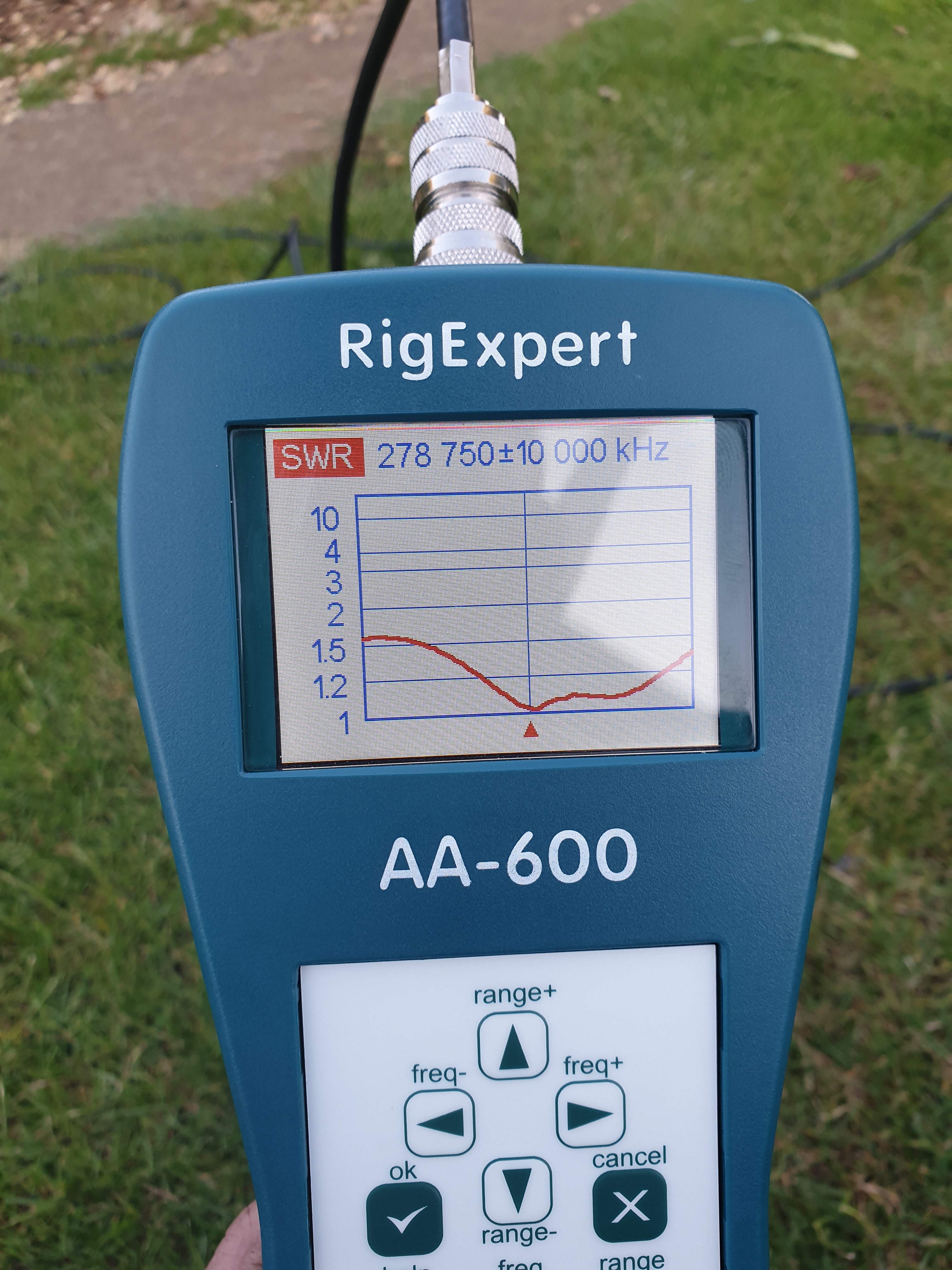
That trace at 128MHz is more the shape I would expect. Now that you have found that, you could try making the tails as short as possible, even if you have to temporarily just twist a thin bit of wire around the rod close to the boom and solder to it - and see what effect that has.
Roger said that his design was based on an ARRL article, which by the marvel of Google, I guess is this:
The coax tails are very short, and also the rods are actually thinner than the ones Roger used, and the article suggests that you adjust the driven element in the range 37 - 39 inches.
As others have suggested, all of these little things could have an effect.
But I think you are right, now that you have found a dip on the analyser, just change one thing at a time - a little bit - and see what happens…
Thing is that i can not make the tails any shorter or you can not plug in the bananna plugs , You push one side in and the other side just reaches to plug in . I tried a choc joining block with croc clips but that did not work too well , only thing i can think is cut the stop clamp down to get as small as i can to reduce the overlap but im only going to reduce by 10mm each side max .