I built this yagi 3 times now and every time i get the swr at the lowest of 3! checked all meaurements on each yagi 4 times , checked all coax leads with a multimeter and on another coax antenna its perfect tried lengthening and shortening and not much change .I even check continuity from the centre core to the driven and same for braid and crossed and nothing shorting out … now im lost !
Any other designs without the cross part driven element ?
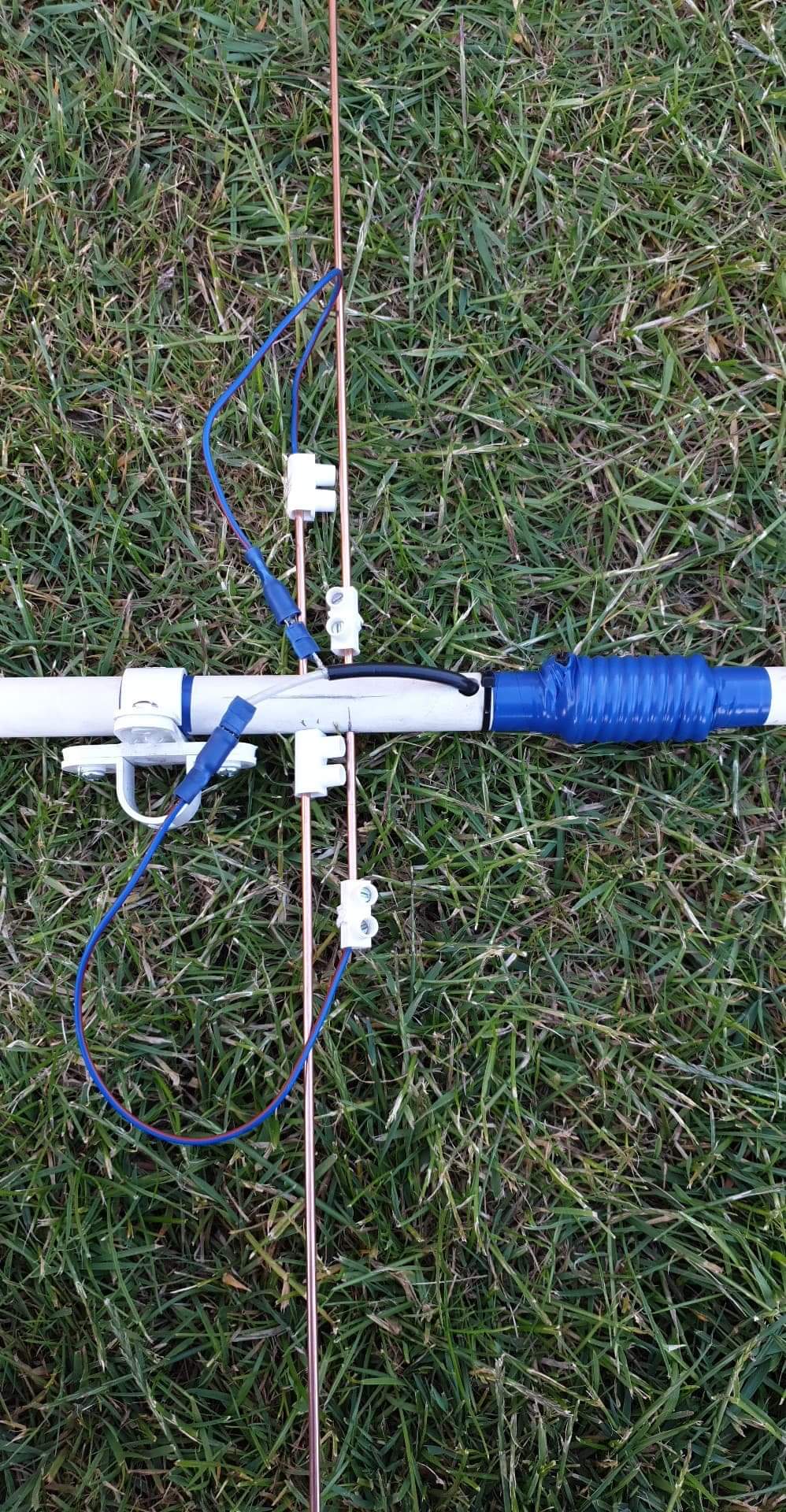
The wires from coax to the driven is long only due to experimenting with adjusting driven length . The original’s was 2" long .
I did think could glue 3 peices of chocolate block on the boom . One for reflector and director and a double peice following the length of the boom. Then the 2 peices you could bend a right angle to be clamped into the block and other side would be the braid or the centre .
I would suggest those 2 massive fly-leads are the primary cause of the poor match followed by the significant over lap of the ends of the driven element.
As well as what Andy says above, the original design uses 6mm diameter rods, and from the photo it looks as though your elements are thinner than that. For thinner rods, they will need to be a little bit longer, and that will apply to all three elements.
Here is a useful link to a calculator which might help:
Don’t give up, it’ll feel great when you have cracked it!
Adrian
G4AZS
Actually, this was the website I was thinking of, my saved link wasn’t working:
It is well worth a read to understand a bit about antenna design, lots of good stuff.
Small crocodolile clips, as used in the SOTABeams portable yagi, are pretty good. But do keep the connections from the coax to the dipole as short and straight as possible…
The Lucar spade is 6mm wide so that suggest 15mm or so of each driven element is poking through the other side of the beam and the fly leads are about 40-50mm long.
Changing to those kind of dimensions may get you into a more acceptable match area.
Just for interest when you measured the match and got 3:1, did you sweep the frequency up or down from 145MHz to find out where the best match was and did you measure the impedance (R+jX) at 145MHz. Those figures would probably suggest whether things were too big or small. Or maybe not.
Andy , i did got from 144 - 145.999 and swr did not move a huge amount all moved was the reflected . The readings are at home . Im tempted to go and get some 6mm Ali rod or tube.
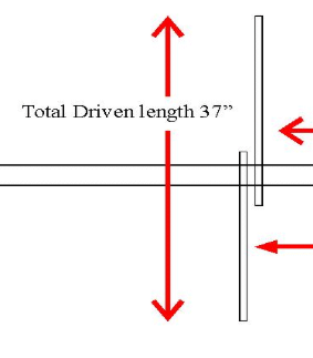
Another thought - the instructions for your dipole could be misunderstood, I think. Refering to this part of the diagram:
When it says “Total Driven Length”, it means the measurement from the tip of one rod to the tip of the other when they are in position - not the length of the two rods added together.
There’s no commercially available VHF beam that really fits SOTA operations in regards of leightweight, small packing, easy deployment, and dB’s. It’s worth to make your own exactly fitting your needs.
I don’t think the difference in diameter is going to explain the whole problem, you say that the SWR is high from 144 to 146MHz, with very little difference, which suggests that something is quite a way off.
Are you putting the antenna up and clear of all obstacles when you measure the SWR? Trying to do this indoors is likely to give strange results, for example… (because you can get strong reflected signals coming back into the antenna)
I see further up the thread that Andrew @M0TRI recently built one of this design, so maybe you could compare notes. (putting the @ sign should alert him to this message, I think!)
It could be bad quality coax cable. I have one flexible RG58 that was only suitable for shortwave. On VHF it was showing similar results: high swr, impedance missmatch and so on.
They’re handheld. I don’t want to sit on a summit concentrating on pointing the antenna in the right direction. Yes, they have an optional mast bracket. It’s made of steel - not that good on a glass fibre pole and quite heavy. It has a wing nut - fiddly in cold and wet weather.
Anyway, what is the gain, F/B, and pattern of these antennas and why don’t the maker give these information? I wouldn’t spend $ 85 for a 4 element surprise yagi (mounting not included).

 Yes, they have an optional mast bracket. It’s made of steel - not that good on a glass fibre pole and quite heavy. It has a wing nut - fiddly in cold and wet weather.