This post is directed to activators who are using their KX2 or KX3 with 4S LiPO batteries. My question is very specific. I have a power cable fashioned with an in-line switch so that I can add a pair of diodes in series when needed to drop the voltage slightly when the batteries are fully charged (16.8V). I’m not really happy with the mechanical reliability of my kludged cable. I’d appreciate hearing from anyone with a good (simple, reliable) solution to this specific issue.
I use a small DC/DC step down voltage converter rated at 3 amps maximum, with the output voltage set to around 11 V. They are cheap from the usual on-line source. I have not noticed any untoward RF hash from the converter. I simply boxed one up in a plastic case with appropriate connections on a DC lead on each side of the converter. Used it for several years with an FT-817 and now with the KX2.
Would it be out of line to consider suggesting a 4s LiFePO4 instead? They peak out at 14.6v which means you don’t need a diode to drop the voltage. My (limited) understanding of forward voltage in diodes is they drop the excess power as heat similar to a linear voltage regulator which means you’re losing a non-trivial amount of battery capacity.
Otherwise I’d agree with some sort of step-down voltage regulator that doesn’t generate too much noise, that way you’re at least getting ~90% efficiency.
You could install powerpole connectors on all the bits, including on each side of the diodes. You can leave out the switch then. It’s all a bit risky though, as you know, the voltage LIPOs are too high for almost any radio. Perhaps include a voltage alarm that is enabled whether the radio is on or not. Odd things happen on summit especially in inclement weather.
You can also reduce the voltage using a FET or a PNP transistor as a series regulator. The 3v lost in the regulator x current drawn is then the lost power. The dissipation in the diode or the pass transistor is lost power.
I have a similar 4S LIPO and plan to use an inverter such as Peter mentioned, but with an overvoltage crowbar circuit as suggested in another forum by Ron vk3afw.
Running the radio from 13v instead of 16.8 should extend the battery life for each charge, as the power used from the battery will be 13/16.8 of what it would be when dropping the voltage via diodes or series pass device. Inverters aren’t lossless though, I will acknowledge that before it is pointed out. But they are likely to be over 90% efficiency and can be left running all the time whatever the charge level is in the battery (this has the potential to over-discharge the battery, of course. no free lunches…)
[quote=“VK1DA, post:4, topic:16227”]
install powerpole connectors on all the bits, including on each side of the diodes. You can leave out the switch then
[/quote]Andrew, I thought of doing just what you suggested with a PowerPole jumper plug. Instead, I think I’m going to get a very small plastic enclosure and mount a DPDT switch on its panel and just switch between the diodes and a short.
[quote=“ki7est, post:3, topic:16227”]
Would it be out of line to consider suggesting a 4s LiFePO4 instead?
[/quote]That’s actually a good idea, except I have a big stock of inexpensive LiPO batteries on hand.
[quote=“ki7est, post:3, topic:16227”]
they drop the excess power as heat
[/quote]I’m no semiconductor scientist but I think the voltage drop is due to the inherent reverse voltage of the PN junction which simply subtracts from the battery voltage when the PN junction is forward biased.
Yep, Ohms law still applies (P=EI). I’m sure you notice your diodes getting warm/hot when you’re transmitting for awhile. Not sure I would want to use a manual switch as I’d eventually screw up and have it in the wrong position! But I’m getting forgetful ;-).
This lost power probably won’t matter as much for short CW activations. You can calculate the operating time reduction and decide for yourself if it’s worth adding a more efficient voltage regulator. Or take more battery packs!
My preferred and proven solution consists of a LT1764 (with R2 divided into a fixed and an adjustable part).
The low dropout voltage of 340 mV @ 3 A allows a max. output voltage of up to approximately 14.4 V with only a minimal heat sink.
To answer a previous question about “why not 4S LifePO4?”… I have a couple of the Zippy 4S2P LifePO4 4200mAh batteries and have used them a ton for SOTA and NPOTA. Those are definitely the best bang for the buck out there and work excellent straight to the rig! However, there really aren’t any smaller than 4200 mAh LiFePO4 batteries if you are looking for a smaller/lighter solution. Especially a cheaper/lighter/smaller solution. So I got a Zippy 2200 4S1P LiPo and built the double diode drop and have been using it exclusively for SOTA the last year and a half.
Barry… I built the diodes up with Powerpole jumpers and taped it to the top of the battery to make it easy to take the diodes out of line, but even after a couple of SOTA activations without a recharge I have never removed the diodes. Just keeps chugging along even with the KX3 at 15w and running 30-45 minutes of a SOTA CW pileup. I think I have to put ~ 1200mAh back in after 2 activations. The battery voltage should be at about 15.2volts after that drain. So with a couple volt diode drop you are still running a pretty solid voltage into the KX3.
Anyhow, diodes were 6A2 6A 1000V (10-pack on ebay for $3.80). Here are a few pix of the setup: https://photos.app.goo.gl/IVnYOy4EeJEynL9l1 The first few pix show it under construction, then the summit shot shows it fully wired up with powerpoles.
Whether saving a half a pound is a big deal, I am not sure… but it was a good project (especially if you have a bunch of 4S LIPO’s around) and it is nice to have a compact battery setup when I need it.
http://www.ad5x.com/images/Articles/AutoLiPoVoltageReducer.pdf
Barry,
This article references a nicely designed voltage reducer. I have the components and the board but haven’t built it yet. Phil Salas, ad5x, has put together a nice descrition of the limiter. He has been very helpful to me.
Gary Kulling
K3TCU
Maybe it has something to do with why I’ve always owned cars with manual transmissions, but I seem to prefer a manual DPDT toggle switch and two diodes to AD5X’s nifty auto voltage reducer
(or a pluggable PowerPole dongle with diodes to reduce voltage or jumper wires to not reduce voltage)
A drawback to using powerpole connectors for all parts of this kind of project is that it is possible when on a summit in the cold and wind to connect the kx3 directly to the 16.8v battery and connect the regulator to itself.
Using different coloured connectors for 16.8v and 13.8v can help, but using a different connector for the dangerous voltage altogether that will not mate with powerpoles would be better. Then only 13.8 can go to the radio.
This can of course be constructed with powerpole components. Put a blank connector shell between the usual two shells, you then have a connector that you can plug a two way connector into but get no electrical connection and no danger to anything.
I guess you could also put the powerpole connectors in the usual side-by-side configuration for normal volts, and one above the other for higher voltage?
I have a KX3 and I use a diode soldered in line between two sets of Anderson power poles - no switch, clean and simple. The unit is then covered in heat shrink. Its tiny and easy to use. I use yellow heat shrink and put an arrow on it in the direction of current flow. Don’t put it in backwards - radio won’t turn on!! I have two in case I loose one.
When my Lipo is fully charged I put it inline and get about 15.8 volts on the KX3 (on the menu for BATT voltage). There is a voltage drop across the diode and also in the KX3. Lipo = 4 x 4.2v = 16.8. Then the diode drops 0.6 volts = 16.2, and the KX3 seems to have a little drop down to 15.8volts.
I say that I can remove the diode but in actuality I rarely do - I just keep it in. I believe Elecraft recommends 13.8volts for 15W, although it works down to 12.8 - just what I’ve read not tested personally.
So if you think about it when each cell is discharged to 3.5 volts = 14 volts - 0.6 diode = 13.4 volts. The KX3 probably reads 13 volts because I have noticed a small voltage drop. This is just about right for you to operate at 15W even with the diode inline with the battery almost drained.
Simple is best - so the only issue is the wasted power across the diode. I use a 1400 mAh battery and I have never drained it even with 1 hour of operating. Within that hour I am calling CQ a lot! I always use 15W SSB for my SOTA activations.
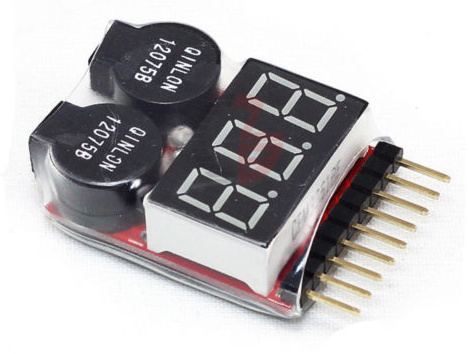
You should use a battery monitor plugged into the cell voltage sensing socket of the battery pack. I use the kind that beeps at a set voltage and the voltage at which it beeps can be adjusted.