My 1/4 wave vertical whip has some nasty common mode current issues. I have some T200-2 ferrite cores. A little bit of digging turned up this design for a 1:1 balun based on this toroid.
Is this likely to do the job and fix my CMC problems?
My 1/4 wave vertical whip has some nasty common mode current issues. I have some T200-2 ferrite cores. A little bit of digging turned up this design for a 1:1 balun based on this toroid.
Is this likely to do the job and fix my CMC problems?
Why not just fit a common choke on the feeder?
I will if I can figure out how to make it with a T200-2 and some wire…
Eric - For ham radio purposes, as you may know, there are two main types of toroid in use:
TYPE 1: Powdered-iron, which has a relatively low permeability, eg T200-2, T94-2
TYPE 2: Ferrite (Nickel-Zinc etc), which has a notably-higher permeability, eg FT240-43, FT114-43
Your preferred AI companion will detail core types, sizes, uses and performance.
For ‘choke duty’ with a coax feeder expect better results with a CURRENT balun compared to a VOLTAGE balun. For a CURRENT balun, a TYPE 2 core is the better choice.
73 Dave
PS Spend a few EUROs on a suitable Ferrite core, and keep the T200-2 for another day.
These seem to be contradictory statements. I think you are saying don’t use type 2 for a choke, but use ferrite such as type 43. I would agree with that.
Richard - Perhaps some confusion with describing the two main toroid types as TYPE 1 (powdered-iron) and 2 (ferrite) - a labelling convenience, rather any reference to mix type.
For clarification:
The better choice for ‘choke duty’ with coax is a CURRENT balun.
Ferrite toroids are the preferred choice for CURRENT baluns.
The size of ferrite core is informed by the power you intend to run; higher power, larger cores. For example, pick an FT-240 for 100 watts, pick an FT-114 for 5-10 watts.
The choice of ferrite ‘mix’ (31,43,61 etc) is informed by the frequency range you wish to cover; AI has the details.
73 Dave
I would absolutely love to, but I am currently on the road so it isn’t practical to get a different core right now. All I’ve got is the T200-2 core I tossed into my bag “just in case.”
Eric - Were you on the road in Scotland, we could have met up, and I would have given you a suitable ferrite toroid ![]()
73 Dave
Hah, noted, next time I will vacation in a place with more amateur radio operators ![]()
You could make a trap with the shield as coil on the -2 core, and a variable capacitor over it.
The optimal core to use needs to consider what is available at the time!
Powdered iron (red #2 material) certainly isn’t ideal, but if that is what you have, then try it and see how it works.
The design for a 1 : 1 voltage balun that you posted on the other thread probably isn’t the best approach, however, as voltage baluns do little to reduce common mode current. But if you have enough wire handy, you can make a current balun / choke (same thing) by winding a pair of wires through the core and connecting that between your coax and antenna.
Normally you’d do that with your coax, of course, to maintain a 50 ohm impedance. But if you don’t have enough coax length, the resulting parallel conductor will provide the choking function, but with a shift in feedpoint impedance due to the impedance mismatch (the impedance of the two wires as a feedline might be 125 ohms or so if they are close spaced). Fortunately, that primarily affects the reactance more than the resistance, so retuning your antenna for lowest SWR may make it usable if the total wire length in the core isn’t too long for the frequency you are using. (One advantage with ferrite is that it doesn’t need as many turns for the same inductance, so less wire, so less impedance transformation due to the impedance of the winding.)
Given that you are travelling perhaps look at this from another angle - If you have access to wire, (any wire), try adding more radials to the bottom (base) of the antenna on the earth side. This may reduce the common-mode currents from going back up the coax braid.
73 Ed DD5LP.
Edit: This sems to be an overlapping thread with
Feeding 1/4 wave vertical - how are you doing it? - Equipment / Antennas - SOTA Reflector
where also adding more radials has been suggested. I personally would try that first, before resorting to the choke. Length of radials - I like 3 metres long and 6 to 8 of them, but whatever you can manage… (I don’t “tune” the radials, rather just lay out a good coverage, on the ground, equally spaced over 360° around the base).
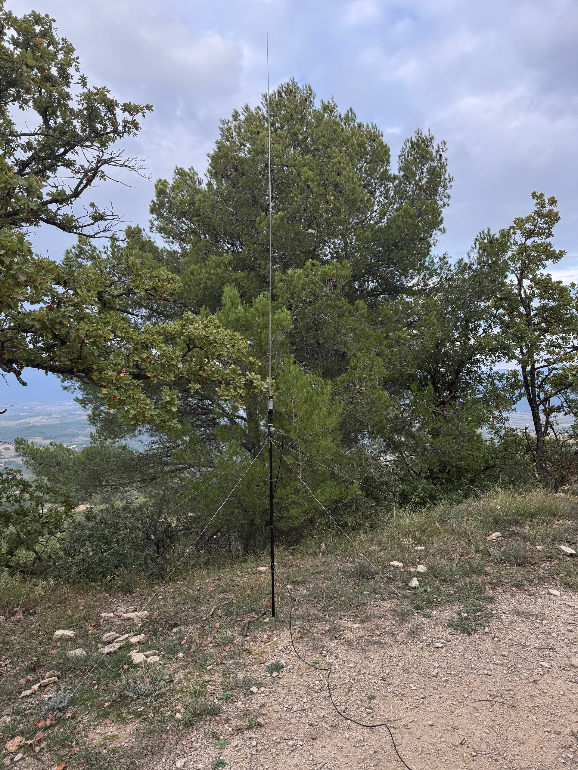
Hi all,
No choke on my side, here using an JPC-12 (1/4 wave vertical with 5 1/4 wave radials) and an KX3, the photo was for 10m
73, Éric F5JKK
That’s a great idea, thanks! What equations or calculations do I need to do to determine how many windings of the wire I should use?
Very nice! But I do not have a tuning coil, just a 1/4 wave whip, a stand, and some radials.
That’s not as simple of a question as it might appear. It depends on the wire size, opoerating frequency, capacitance between the windings, the details of your antenna, and whether or not you are using a tuner.
So I took the pragmatic approach: a T-200-2 core from my junkbox and some scrap hookup wire I had on the workbench, wound a choke, and measured it.
With two wires in parallel, I got 15 turns on the core. You probably could squeeze a few more, but that was the length of wire I had, and probably is a reasonable number.
The choking impedance on 20m was 300 ohms, which is certainly less than ideal, but would probably help with resonant radial(s) (which are likely to be 15 - 20 ohms or so). It was higher on 15m, and close to self-resonant on 10m (a couple thousand ohms).
On the other hand, the 68cm of wire used in the winding causes an impedance transformation due to the impedance of the feedline. I used insulated, stranded hookup wire, which was not as cooperative in laying neatly on the core as might be the case with solid magnet wire. That affects the impedance of the short feedline.
I found a 51 ohm resistor and measured it - SWR was about 1.2 : 1 at 30 MHz. I connected to one end of the winding and measured the SWR looking into the other end. At 20m it was 1.9 : 1. At 30 MHz it was 3.3 : 1. If you are using an ATU, this might not make a difference. But if you are feeding it directly from the transmitter (which is one reason for using a quarter wave wire) then it won’t be as satisfactory.
And that is one of the major trade-offs: the more turns (up to a point), the higher the impedance, but that requires a long feedline, which makes the SWR worse with a 50 ohm load. Of course, winding with 50 ohm coax eliminates that problem, but only if you have some available.
I will note that my measurements aren’t perfect, which particularly will affect the self-resonant frequency of the choke. That’s a problem with too many turns: at some frequency it starts looking like a capacitor instead of a choke coil. And the impedance was mostly reactive (inductance) without much resistance component: that means that, if the antenna is capacitive, it can cancel the choke impedance and actually make matters worse with the choke in place.
An effective choke will have a short enough winding (fewer turns) so there is little impedance transformation, the self-resonant frequency is well above the lowest desired operating frequency, and it will provide resistance instead of just reactance, to make it less dependent on the rest of the antenna system. Those are all reasons why ferrite is preferred over powdered iron cores.
There are techniques that might improve performance over the simple coil that I wound, but it’s probably typical of what you would encounter trying to wind a choke in the field.
Thank you very much for testing! That makes good sense. I’ll try that. I do have an ATU, but it doesn’t fix the CMC problems.