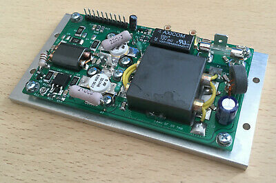
What is the difference in performance or something else… with the 5:1 UNUNs with copper pipes
Like the one attached and other designs like X turns around a FT240/FT140 etc… for example? (like popular 9:1, 4:1 etc)
Im talking about the general design not the ratio (5:1) difference.
That transformer is what the Alpha Antennas “Alpha Match” and the Chameleon Matching thingy is based on. I have had mixed results with the Alpha version mounted mobile. Requires a tuner.
Assuming that you meant “But what is the antenna theory”, it’s a transformer with a specific turns ratio between primary and secondary. From the turns ratio an impedance transformation can be derived. The impedance ratio is the square of the turns ratio. The purpose of the ferrites is to increase the inductance of the wires passing through the cores, to allow them to operate as a transformer at a lower frequency than would be possible if the cores were say, cardboard or plastic. Using ferrite cores allows for reduced number of turns, which means lower losses. However ferrite cores have limits to their power handling and also they have ideal frequency ranges; outside of their ideal range the inductance doesn’t have the same increase.
Usage with an antenna. If the antenna impedance is not close to the impedance of the feedline in use, some means of transforming the impedance of the antenna to that of the feedline must be used. For example a high impedance antenna of 2500 ohms could be fed by 50 ohm feedline if you had a transformer with an impedance multiplication of 50. 50 is not a square of a simple turns ratio. The nearest perfect square you can find is 49 which would use a turns ratio of 7.
Tuned circuits can be used for changing impedance too, in an adjustable antenna matchbox or antenna tuning unit. The antenna matchbox has the slight disadvantage of requiring tuning for each specific frequency or band used. It doesn’t tune the antenna, it transforms the impedance of the antenna so it looks as if it is 50 ohm.
Broadband transformers like this can transform the load impedance to one that is usable with typical feedline/feeder and operate without adjustment over a range of frequencies and bands. A typical frequency range for such devices is 3 to 20 mhz, 3 to 30 or 2 to 10 MHz depending on the cores used, the number of turns, thickness of wire, configuration used. If increased losses are tolerable for the convenience of a no-tune device, wider frequency ranges are possible.
Entire text books have been written on this subject. I hope this description provides the basics.
No doubt some of the finer points are missing from my description will make the purist weep. But I think this is adequate for practical applications.
I have a basic understanding of the UNUN/transformer theory.
Do you know the theory behind this design in the image (with the copper tubes etc) and the “classic” FT240/FT140 ring with a number of turns around them?
Do you get what I mean or Im giving the wrong description?
These are all variations on a lossy transformer. Alpha and Chameleon don’t actually tell us that, but the broadband SWR charts tell the story. An efficient antenna has sharp SWR dips at resonance. Resistive losses make those very broad.
The classic design of this sort is the Comet CHA-250B. Comet is totally up front about the losses in their description of the transformer.
CHA-250B Transformer Section
This is a the “magic” behind the CHA-250B, the transformer matching section.
The transformer on the original CHA-250 had smooth sides. The current version has a heat sink to dissipate heat created inside the transformer.
Yes, some of the RF that enters the power feeding section is turned into heat rather than transmitted as RF, but that is one of the compromises needed to create a broad-band, low SWR, multi-band HF antenna with minimal visual impact.
I don’t trust either Alpha or Chameleon because they don’t explain that tradeoff.
There are a few efficient broad-band antenna designs, but they aren’t convenient for portable use. Either they have fat, low-Q elements (cage dipole, bowtie dipole, discone) or multiple elements (fan dipole, log-periodic dipole array).
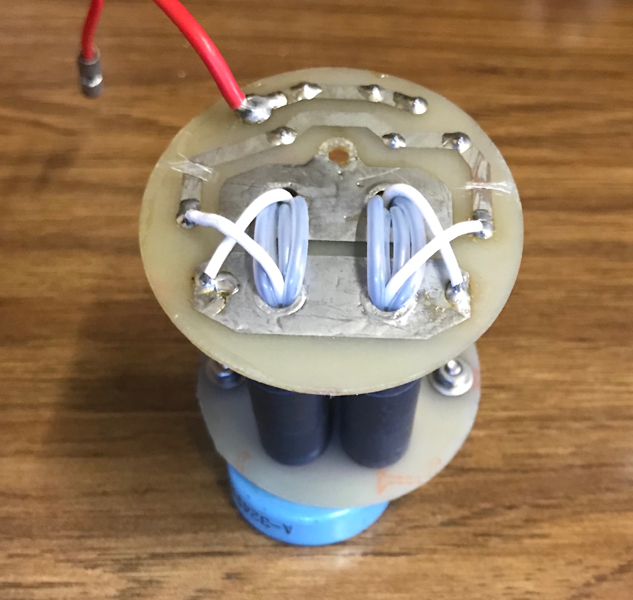
The copper pipes form a very low loss conductor to use as the primary of the transformer. You can see that if you trace the connections in the diagram, the input to the transformer from the coaxial connector goes to the left copper tube, across to the other tube at the top and then the bottom of the right hand tube, connects to the earth side of the coaxial feed. That forms the primary of the transformer.
The secondary of the transformer starts at the lower right hand side where the wire connects to the earth side of the primary. Several loops later it connects to the output connector.
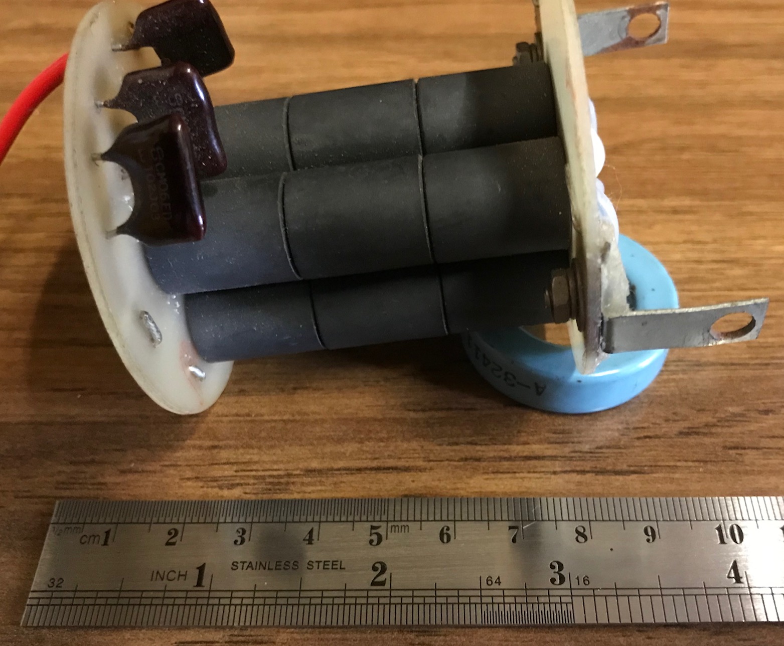
The copper tubing is used in the transformers inside higher power amplifiers to reduce the losses of ordinary wire when very high currents are needed by the low impedances of transistor amplifiers. But they have many more ferrites than 5.
I don’t think copper pipes are necessary for an antenna transformer. And I am doubtful whether a single turn primary is sufficient for the lower HF bands. That would mean it is just a few bits of wire in open space with a coupling loop.
But as Wunder K6WRU has pointed out, the device isn’t achieving low loss power transfer, so it amounts to a smoke and mirrors device.
This type of transformer is used in all current RF amplifiers. It transforms the very low impedance of the transistors, usually switched in push-pull.
Winding ratios of 1: 3 are common. The two metal tubes are regarded as one turn. A block is used instead of many ferrite rings. This is clearly visible in the picture.
Here, however, a very low impedance of 5.5 ohms is transformed to the 50 ohms at the output, so that the losses due to the transformer’s own impedance and capacitive coupling remain low.
The situation is quite different with the usual transformers for EFHW antennas. Here primarily 50 ohms are brought up to maybe 3200 ohms.
One turn is inadequate for 50 ohms and the capacitive coupling of the tightly wound secondary winding limits the upper limit frequenc enormously.
Note the higher impedance windings go through the copper tube. This is an attempt to increase the coupling between the tube single turn and the wire turns. transmission lone devices inherently have close coupling of the windings but transformer devices will not, even with a good core.
Test your device with a resistive load and if the SWR is less than 1.25:1 across the range it will be qood for QRP.
I have been playing with some cores and revisiting work I did several years back on 1:1 and 1:4 transmission line transformers. I have built a 9:1 unun and a 9:1 current balun. Both do a very good job from 1.8 to 30 MHz and 3 to 50 MHz respectively. I can’t measure the losses as they are too low for my instruments to show. I usually build two and connect back to back with the rig on the input and an absorbing watt meter on the output. The resolution is a couple of percent.
I’ve also built a 49:1 transformer. It shows up to 2:1 swr from 3 to 30 MHz when connected to a resistive load of 2,500 ohms. This seems to be par for the course. I need to build a second one to see if it is efficient.
The reason for less than a perfect match is primarily the leakage of flux as not all turns see the same flux. At the higher frequency end some capacitance compensation brings the ratio back to near where it should be. This is necessary due to the distributed capacitance between turns.
Some of the cores I use are type 42 ferrite and others are unknown being bargains bought for a low price. I wind 8 turns of 100 ohm wire transmission line on the core and test it as a 4:1 device. If the results look OK then I put it in my Good box. CAT5 cable has 100 ohm balanced transmission lines inside. Cut off a m length and strip out a pair, Really good for medium sized ratio devices.
Hello I’m new here and wanted to dredge up this old thread. I’m curious about the purpose of the half turn. Is it to get the impedance ratio of the unun to 5:1? The square root of 5 is about 2.24, so a 5:1 impedance ratio would have a turns ratio of 2.24:1. A 2.5:1 turns ratio give an impedance ratio of 6.25:1. Also, why is this unun lossy? A 5:1 impedance ratio unun should not be inherently lossy. Many thanks.
G8JNJ used to have an excellent series of articles describing these transformers (which is where the previous drawing came from), but they appear to be offline now. You might find them copied on other sites, or via the wayback machine. He actually came up with an improved design (which was then copied by at least one manufacturer without giving him credit). He also measured the radiated RF vs. a reference antenna on each band, using different transformer designs.
Basically that folded stub doesn’t work as half a turn. Rather, it increases the losses to improve the SWR bandwidth at the expense of efficiency. The losses are due to the choice of ferrite and the winding configuration.
Remember, the radiator that these transformers are used with is not all that wideband by itself. Yes, if you use large enough aluminum tubing it helps reduce the impedance variation with frequency, but there is a practical limit to what you can manage. The impedance ratios are chosen to try to get a reasonable SWR over a reasonable range of frequencies, but the radiators attached to them rarely provide 250 ohms or 450 ohms or whatever impedance that would result in 50 ohms. Most hams can measure SWR, but few can measure efficiency with a convenient meter in the shack, so you can guess what many antennas are optimized for…
Thanks that clears up a lot for me. However I’m still trying to figure out the impedance transformation. My eyes count 1 primary turn and 2+ something secondary turns. Is this correct and does this give you a 5:1 impedance transformation (2.24:1 turns ratio)? Not that an exact 5:1 is important but I’m just trying to understand this.
I would also interpret it as 2.5 : 1 turns ratio, as the folded stub shouldn’t contribute anything (the currents are in opposite directions in the folded piece, so should cancel each other). That would give you an impedance ratio of 6.25 : 1 in theory (312 ohms). But it may be that, with the proper choice of ferrite, there is an effective series resistance in the folded stub of ~60 ohms, which, added to a 250 ohm load, would give a good match. (I know that G8JNJ’s design relied on a particular mix of ferrite to find the right mix between loss and impedance ratio, but I don’t remember the details.)
Many thanks guys. I now understand the transformer in my Chameleon Antenna EMCOMM III. I took it apart (could’nt resist) but could still not understand how it works. I have had decent results with it but I do undertand it is somewhat of a compromise antenna.
I live in an HOA so I have to be really carefull not to get busted with an antenna. The 130 foot antenna wire is green and goes up and over a tree in an inverted V configuration and the transformer is mounted to the side of my house. I do notice when using FT8 that probably about 90% of the time the other station has a better signal report than mine even when I’m using 100 Watts. However a 130 foot antenna is not ideal for the upper bands so I’m not sure how much the transformer is the fault. I dare to only put up one antenna wire so this is it. I do like that I can work all the HF and 6 meter bands with this setup even if it is a compromise antenna.
I might try a 9:1 unun with an external tuner and see if I get better results. Many thanks I have learned a lot here.