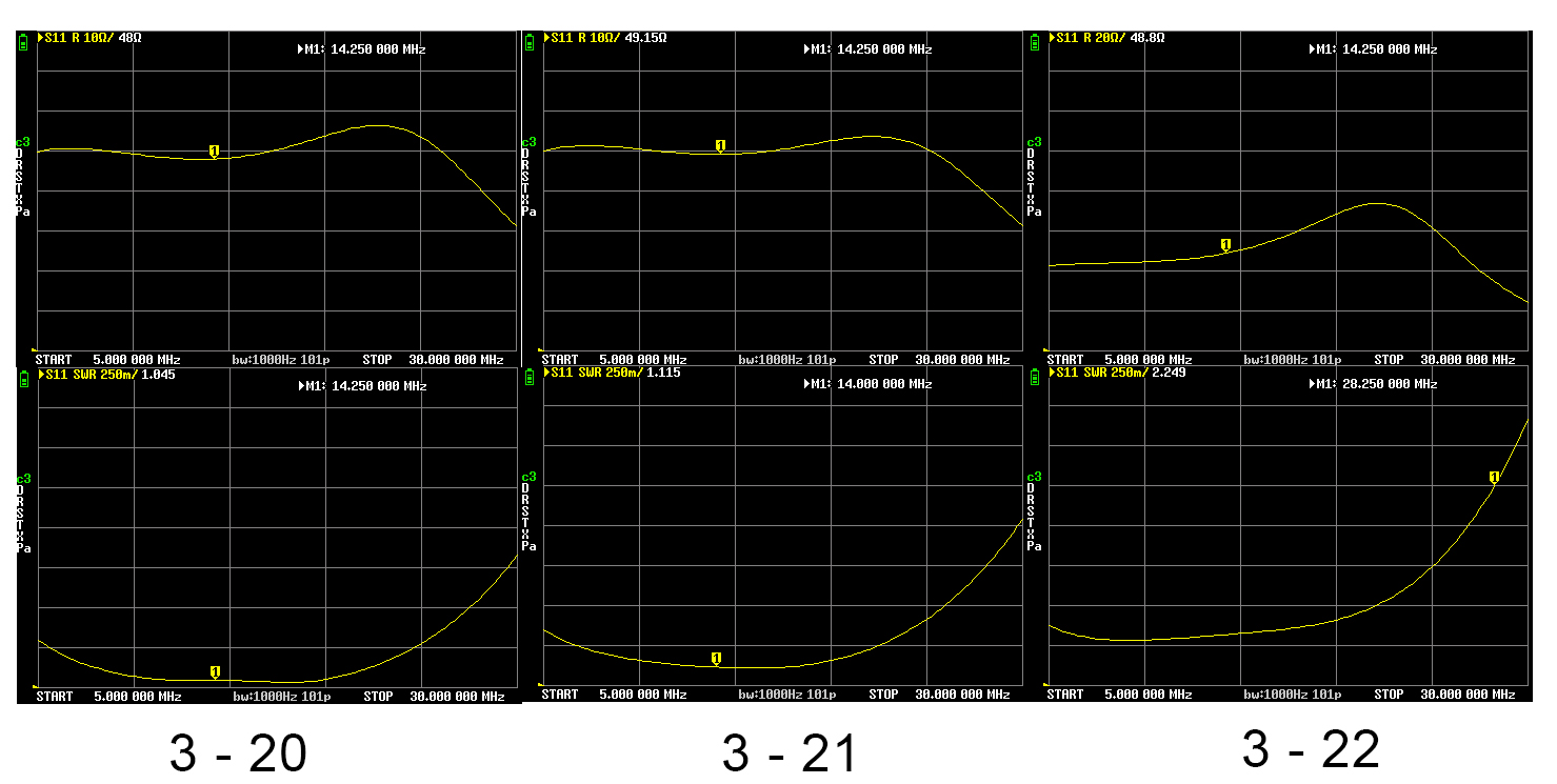
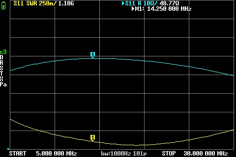
Then I ran some tests with my vna and a 2525 ohms resistor.
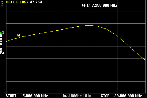
Here is the result :
I get a nice 50 ohms from 5 to 25 MHz but then it’s a collapse at 28 MHz…
Then I connected a 10m antenna wire and measured indeed a good 1.1 on 20m but a slighlty less good on 10m, close to 2.
First question :
I red a lot of articles and posts but I’m still very confused about the way to improve the situation on 10m since I still don’t understand the physics behind tis behavior… Is it the permeability of type 43 toroid causing it ? What else should I improve ? Capacitor ? Wiring ?
Second question:
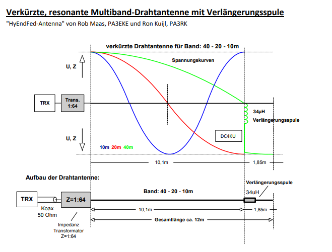
If I want to add 40m band to this antenna in a coiled / shortened version … I’ve seen a commercial antenna like this using a 35 uH coil and a 2m extension of antenna wire. Can someone tell me how it is calculated ?
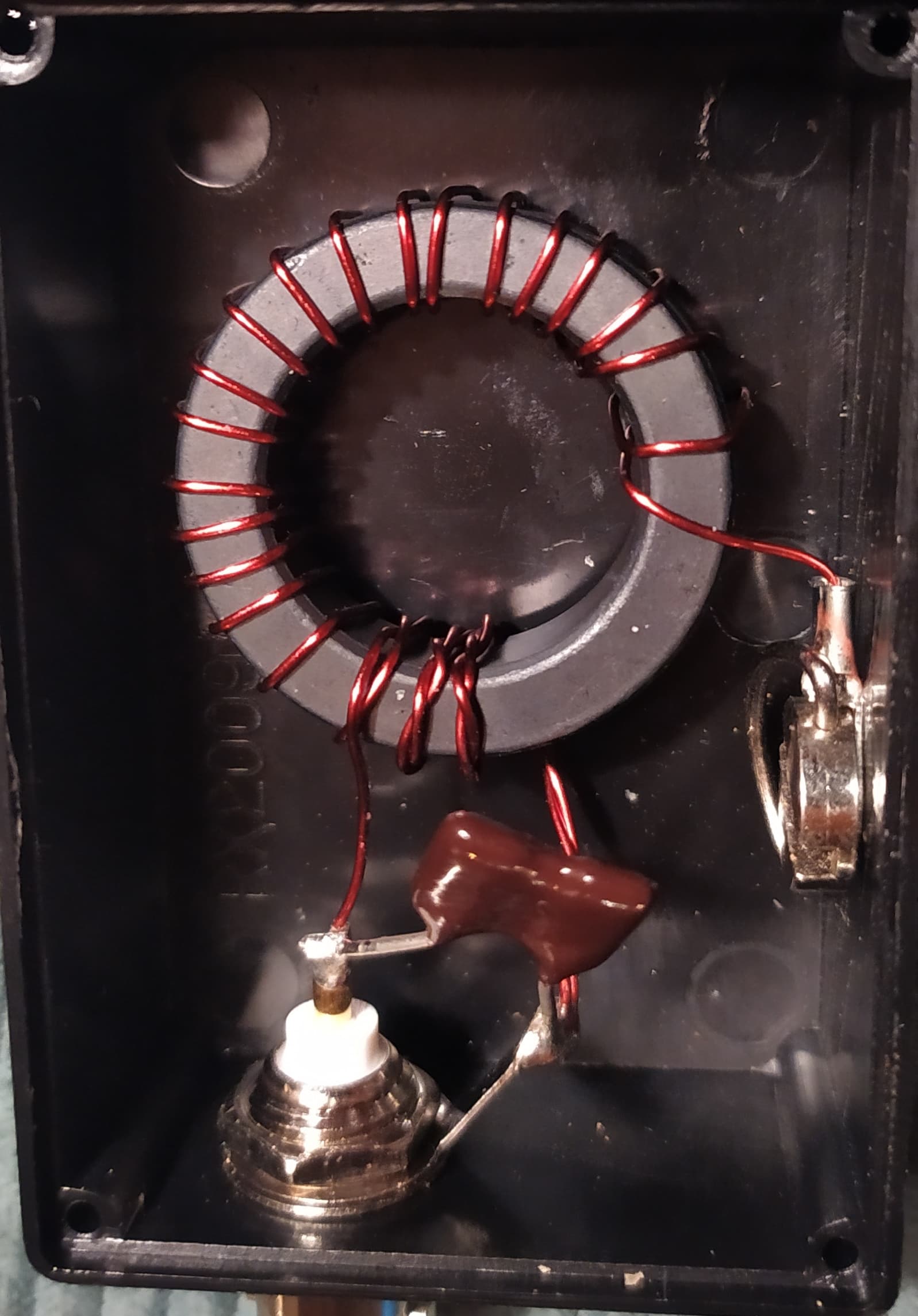
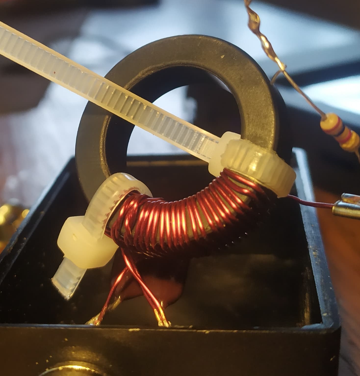
What we see is 3 primary and 22 secondary turns.
From a purely mathematical perspective, this results in an impedance ratio of 53.78 (50:2689 ohms), i.e. the load resistor for the measurement would have to have this value.
To successfully implement your project, the number of turns on the secondary side would have to be reduced by 1 turn to 21 and the load resistance would have to be chosen at 2450 ohms.
Of course it would be interesting to see the result of a transmission measurement (S21)…
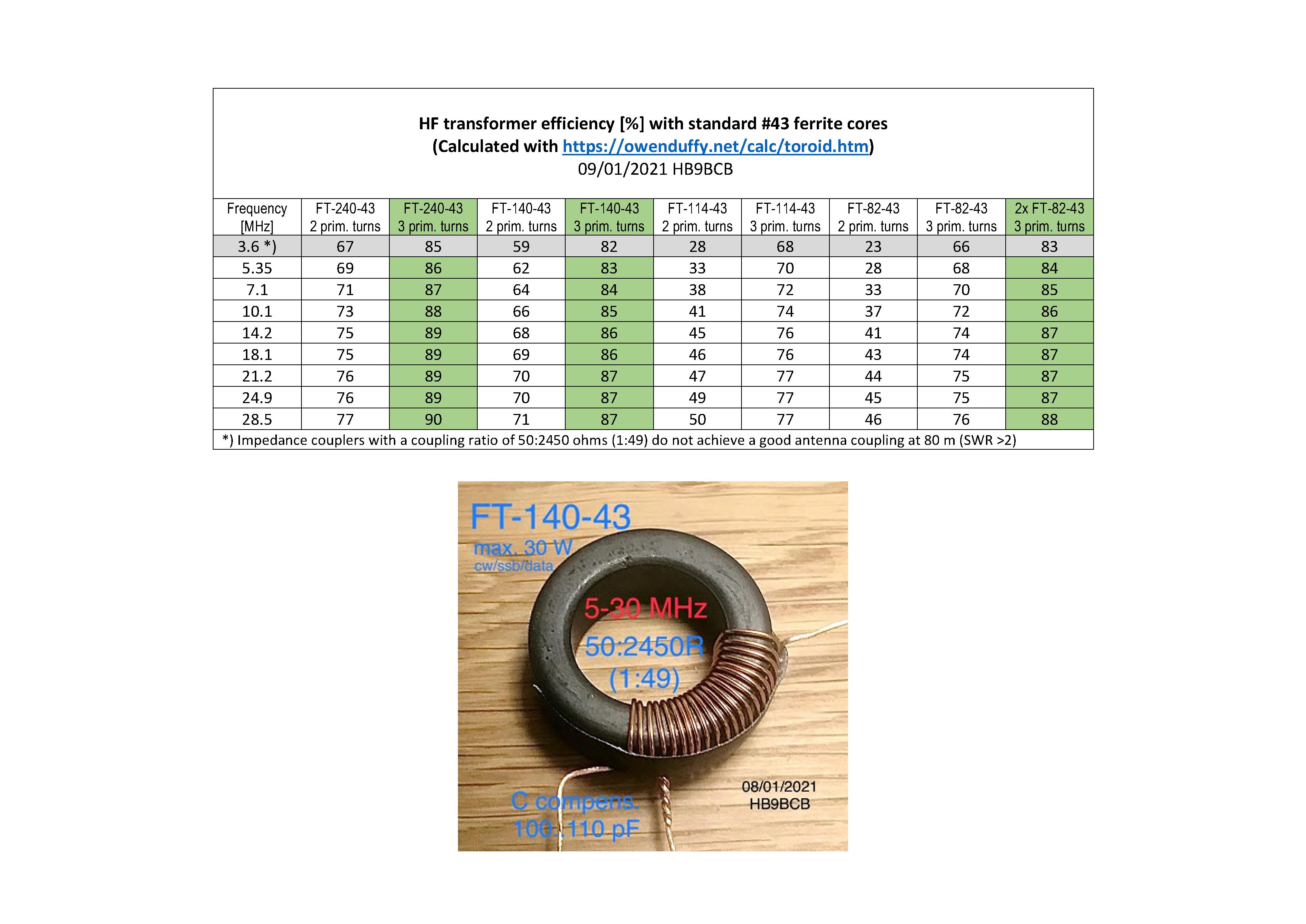
I have already built a few EFHWs and used different -43 toroidal cores depending on the application. The efficiency of 140-43 is probably better than 114-43. (see the table that Heinz has posted) But that doesn’t matter to me in QRP practice. For me it depends more on the design.
When measuring with the NanoVNA, it is possible to measure something incorrectly at higher frequencies… e.g. if the measuring cords for the resistance are too long, there are problems at 10m… and everything acts as an antenna.
I have only made EFHW for 40/20/15/10m and used the corresponding wire length of approx. 20m. I have no experience with coils… but with traps. But that is not the question here.
I always build the transformer first… and then cut the wire to length. There are always small differences. This has to do with the slight scattering of the components and wires. Sometimes it is interesting to unwind or apply a winding.
The SWR of the antenna also depends on the design in the application. I have not yet experienced a shift in the resonance point.
I think your transformer looks good and you should do a practical test with a wire!
If it is a multi-band EFHW, which is 2 or 4 half-waves long on 28 MHz and has a VSWR of 1 on 14 MHz, this antenna is inevitably too short on 28 MHz, i.e. the resonance will be around 150-200 kHz higher than expected.
This arises because the mechanical antenna length for harmonic frequency bands is not an exact multiple of the antenna length of the fundamental frequency.
The solution would be to choose a compromise antenna length, which, however, does not exactly produce a satisfactory result (SWR) on the lower and upper bands of a 40-10 m EFHW for use without an ATU.
For this reason, for my small radios without an ATU, I only used monoband, linked and later trapped and hybrid EFHW antennas.
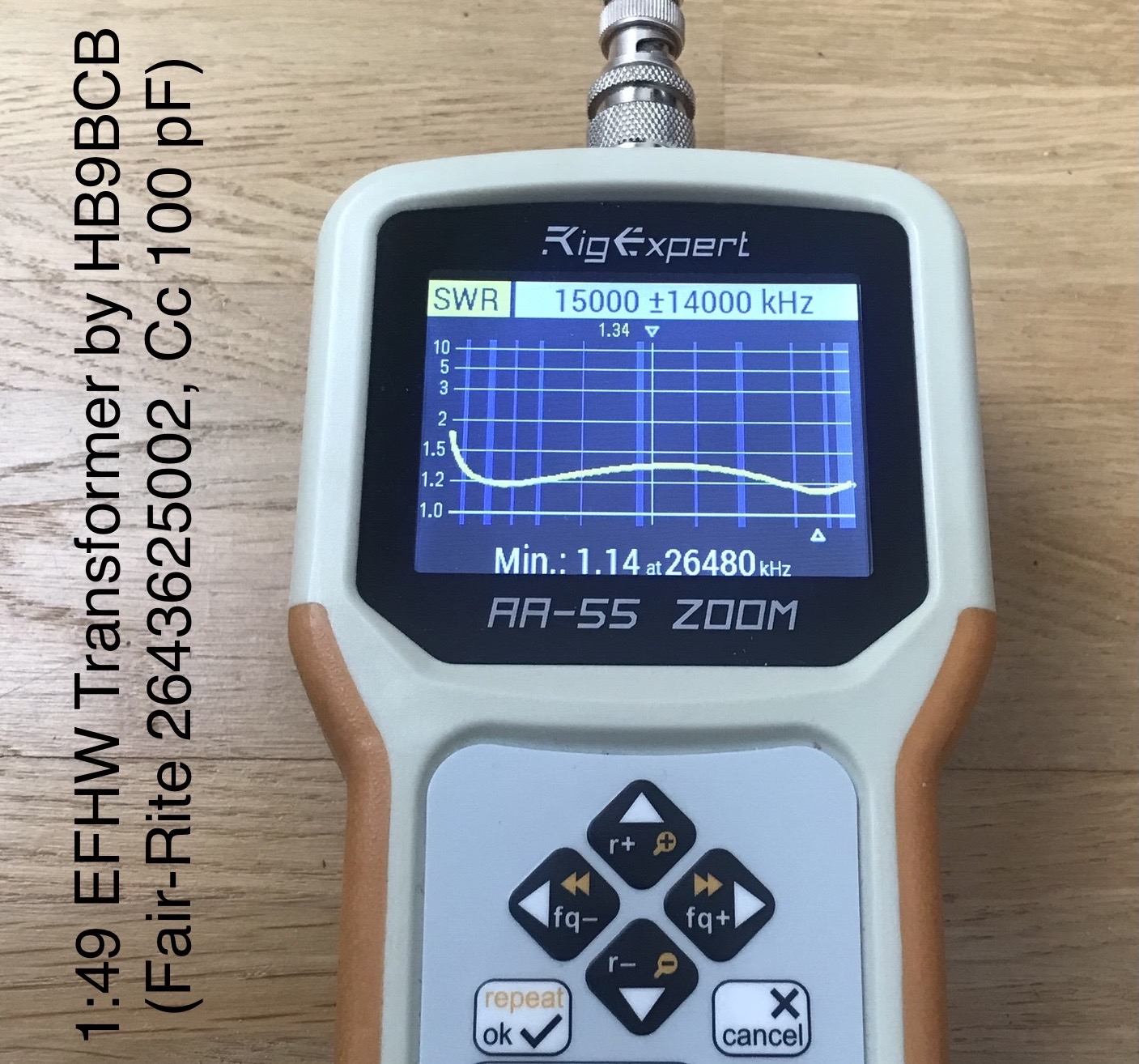
EFHW Transformer design verification
The main purpose of a reflection measurement with a non-inductive resistor of the nominal value on the workbench is for the designer to check his design (e.g. to favor the low or high frequency bands or for broadband applications). For information only, the photo below shows the VSWR curve of one of my 1:49 EFHW broadband transformers.
Due to the significant increase in the VSWR at approx. 20 MHz of your EFHW transformer, it must be expected that this also applies to the transmission losses (s21) and that this transformer is therefore not sufficient above approx. 20 MHz for efficiency reasons.
What else could you try? If you want to stick to this toroidal core size, all 21 turns could be pushed together completely so that the turns on the inside lie against each other without any gaps.
Indeed is not looking normal.
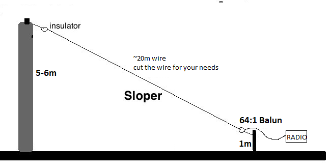
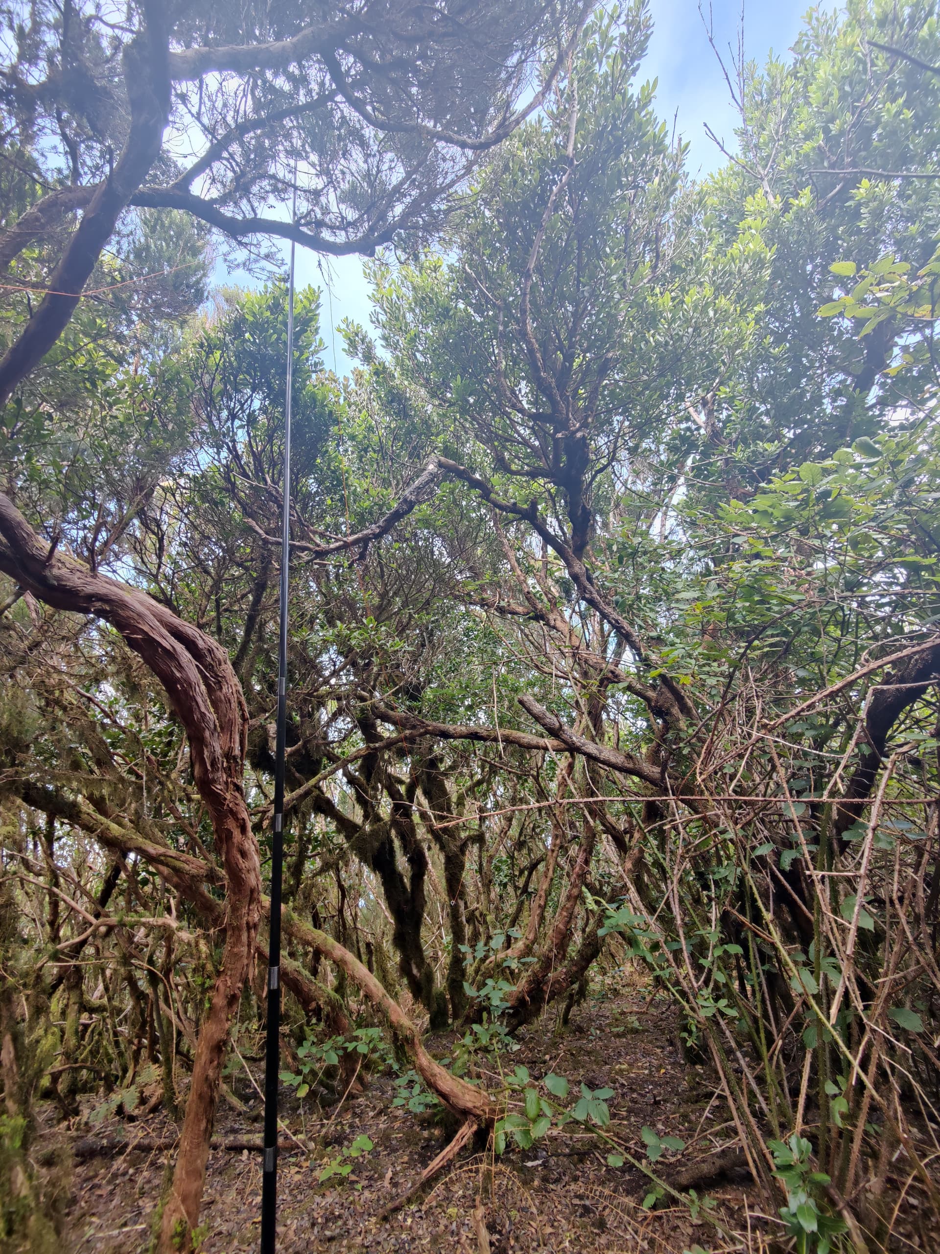
Try a longer wire like 20m (19,xxm) build up as sloper. I used only ~20m and only 2 turns primary and 14 secondary.
But the SWR should go much deeper.
In my case on 14 MHz its always deeper then at 28MHz.
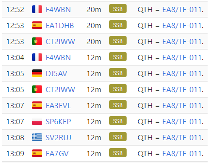
My Antenna is resonant on 40m, 20m, 15m, 12m and 10m. No tuner is needed.
HB9BCB Thank you for those explainations. I apreciate. I will give it a try and let you know.
IN3JIB I do not want a 20m slopper. Originally I thought about EFHW because of limited footprint (5 to 10m is acceptable to me) and resonance on desired frequency (I save the 200g of the tuner in my bag). But now, here is the trade :
EFHW 10m : + 6m footprint only (sloper) + no tuner on 20m / - work only 1 band so far
Random wire 16m : + work 40 to 10m easily / - wider 11m footprint (inv V) - 200g tuner to carry
Since I already own the tuner, I’m considering changing my plan towards the random wire solution to be honest. But first I will try the modifcation of the transformer.
The toroid material. There seems to be quite large tolerances, according to @HB9BCB, who published his results on this reflector with the same material (sorry, I can’t find it anymore).
The environment and the height and configuration of the antenna.
The length and layout of the “counterpoise”.
About your second question:
Good question and I don’t know the correct answer (the calculation for shortened dipoles or quarter waves doesn’t apply). But it doesn’t has to be exact. If the inductance is a bit higher, the remaining wire will be a bit shorter with a narrower bandwidth, and vice versa.
Some time ago I published a document describing a portable 7-band EFHW antenna, about 20m long, with a bypassable coil. How did I find the perfect coil inductance? First I estimated it, and then empirically removed some of the winding until it fit .
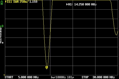
It did for sure. After adjusting a bit the wire antenna lenght, I have now a nice SWR < 1.5 on both 14 MHz and 28 MHz (I had to make a little compromise to fit the two band as explained by HB9BCB ).
Now that the base of my antenna is working as intended, I will try to add the shortened 40m section. But enough for today
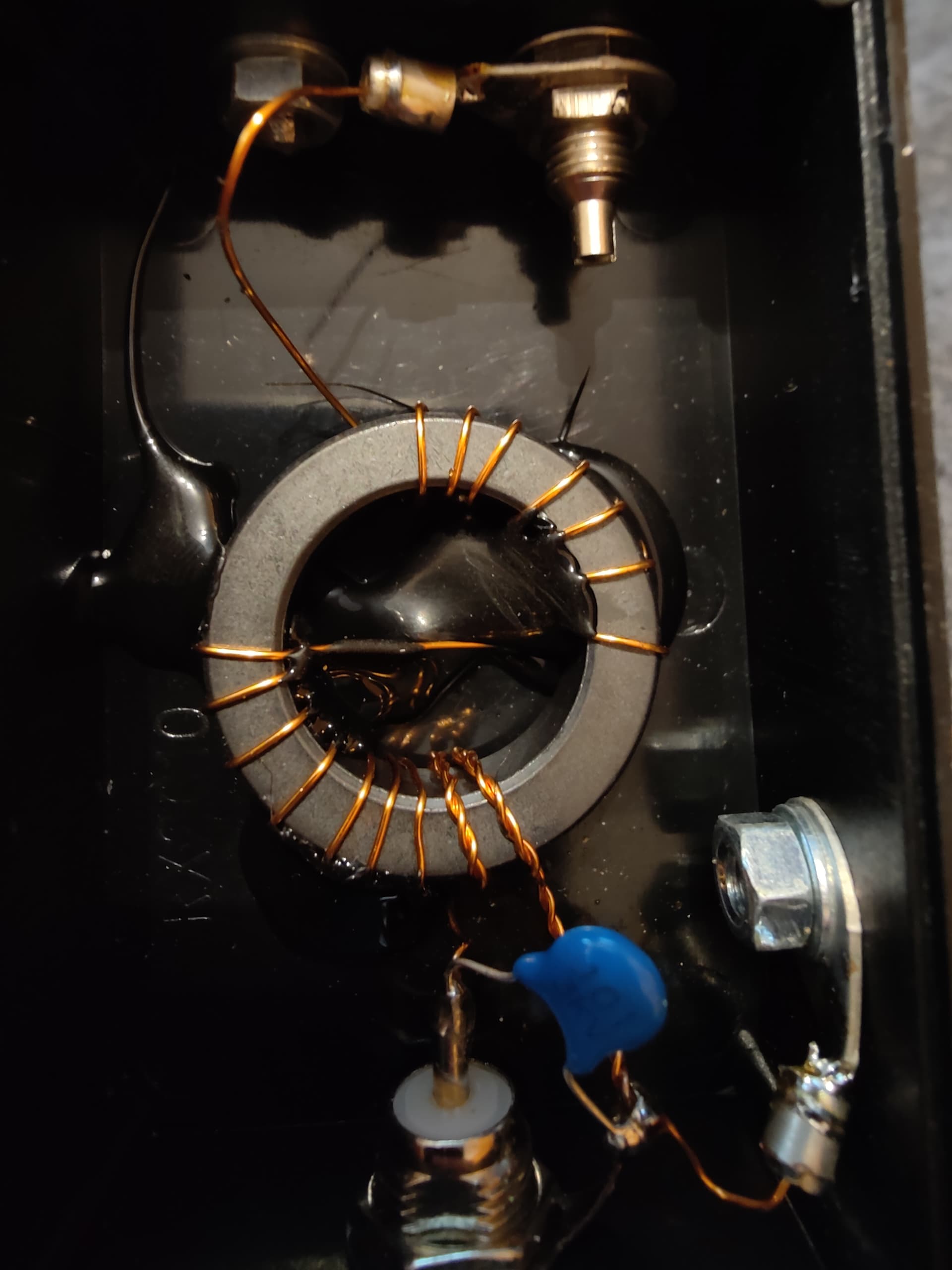
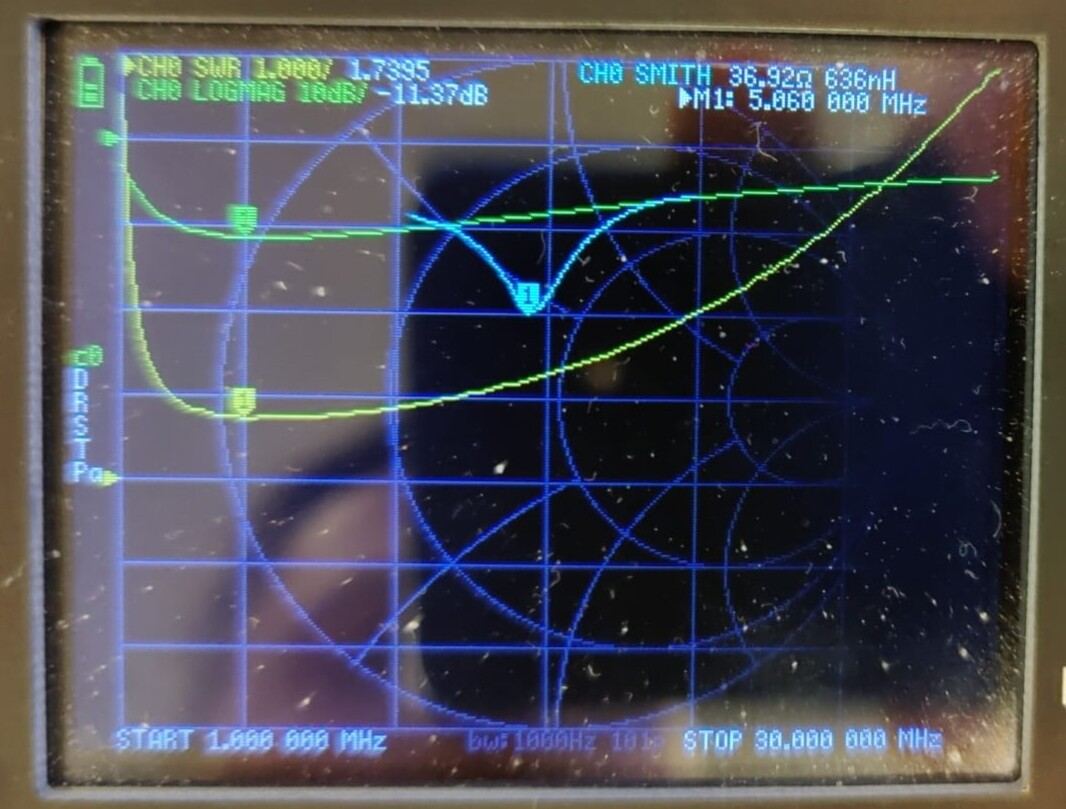
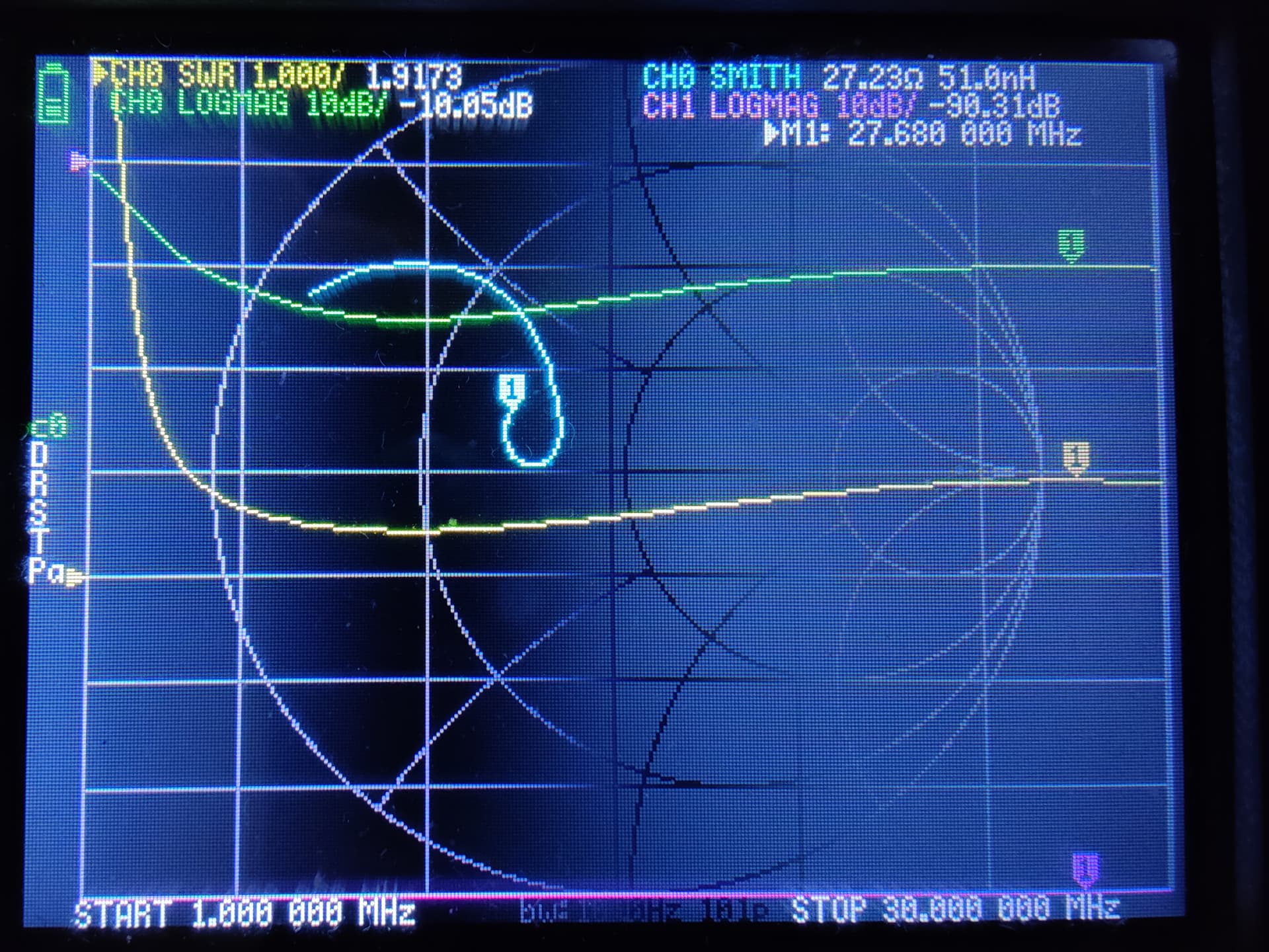
If I’m measuring my transformator with 3.2k it looks like that.
Should be 50 ohm but isn’t lmao. But my antenna is working great and if I’m measuring directly in the field its almost 50 ohms.
The dimensioning of the coil as a choke for the frequency bands 20 and 10 m could be done according to the rule of thumb, according to which a reactance of around 10 times the system impedance is required, i.e. at least 500 ohms. The maximum required coil inductance of around 6 uH would then be required for the 20 m band.
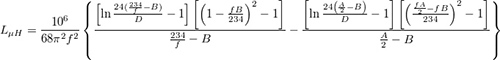
The dimensioning of the coil to electrically extend the existing antenna length to a 40 m EFHW could be done like a loading coil for a shortened quarter-wave antenna. In this view, the distance between the feed point (end of the existing 20/10 m EFHW antenna) and the loading coil would be 0 m.
With an online calculator (e.g. from M0UKD) you can easily see that the required coil inductance for a short antenna tail on 40 m is much larger than that previously determined for the choke function and that this function is therefore automatically fulfilled.
Well thank you again if I use that method and use a bit less than 2m as a wire length I retrieve exactly the 35uH of the commercial ones.
What is still not super clear to me is how you would chose the length of the wire. It seems like in the range from 0 to lambda/4 , the required inductance varies from infinite to 0. So I guess we want the wire short enough to meet the dimension constraints, knowing that shortening the wire is enlarging the coil, and as a consequence, reducing the efficiency. Am I correct ?