Martin,
I just tried to look at your project in Kicad, some of the required library files are missing from your github repos …
myparts
myparts2
sc4503
gobox-parts
kicad complains about them when opening the schematic.
73, Colin G8TMV
Martin,
I just tried to look at your project in Kicad, some of the required library files are missing from your github repos …
myparts
myparts2
sc4503
gobox-parts
kicad complains about them when opening the schematic.
73, Colin G8TMV
On Barry’s parts list are three different LED’s. Can anyone yet say which might be the best choice???
TNX - Fred kt5x
Hi Colin,
I will try to fix that, but I think those are just libraries I use in other projects, so the missing components are not used in this case. Maybe I have to clean up the list of my default libraries.
Martin
Hello,
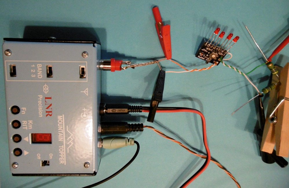
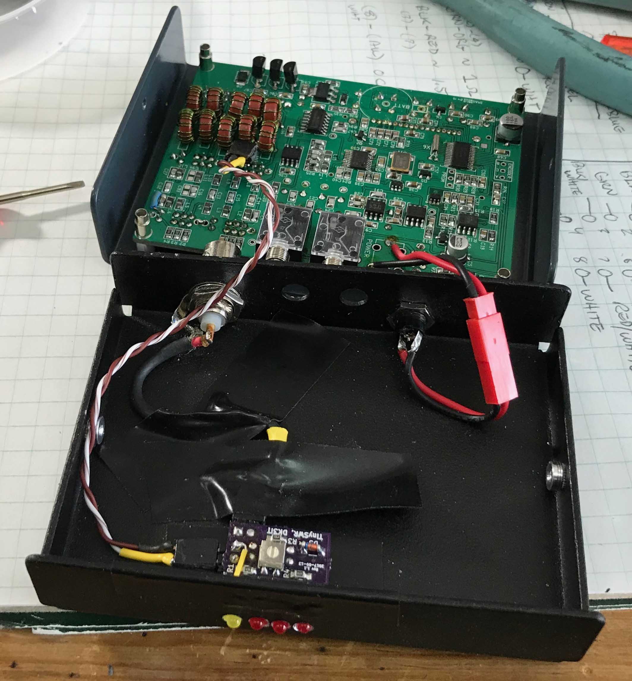
today I got a little extra time and I finally soldered all pending leds.
I missed the yellow led and I finally assembled all 4 leds the same: they are red color, Mouser ref. 604-WP710A10LSRD.
Their forward voltage is 1,65V, current 2mA, and are 25 mcd luminous intensity.
According to your comments, I had to swap my connectors, so ANT was used for RIG, and the RIG in the PCB was used for the Antenna.
So far I did an initial test with this setup:
First I powered the rig with a 2S Lipo (7,5 Volt), I guess around 2 watt out. I put the 50 ohm load. Key down and the first led light up, all right!
Then switched to 100 ohm and then 3 leds light, being the first the brighter.
I played a bit with the inbuilt potentiometer and got only 2 working, as expected. The second one with little bright. The potentiometer is near its middle position.
I replaced the battery and put a 3S lipo (12V - 5w out). With the same 100 ohm load again 3 leds went on. I adjusted the potentiometer and got only 2 leds working as expected.
REMARK: it is important to isolate every led because the light of every led travels around and it seems the others are lighting!! I used pieces of paper between them for the testing.
Once the PCB is inside a box every led will pass on its own hole, being then well isolated…
PENDING TEST:
I need to repeat the test with some more resistors to fine tune the SWR reading.
Power level is important and affects the brightness and number of leds lightning, therefore I will adjust with 5w that is the normal level I will use with the rig.
Note the clothes peg used to join the 2 resistors of 50 ohm together. I’m running off crocodriles!!
The project is working well. Wishing to have it ready to operate in the box, I’ll let you know more soon.
73 de Ignacio
Dear Ignacio:
Thanks for your great report! I am glad to see that the Open Hardware way of sharing ham radio designs seems to work well!
BTW, the yellow or orange LED for RF1 is not as critical as the red ones.
73 de Martin
PS: When adjusting the trimpot, I recommend to use a position at which the first LED at least glows a tiny bit a a SWR of 1:1.2 or so; this gives you confidence that the circuit works.
Dear all:
Yesterday, I got the boards for the latest revision of the layout (2017-10-24), as now available via OSH Park. I just assembled a new prototype and can confirm it works like a charm. It works best with 2.5 - 5 W, but can be calibrated to also work with 1 W. The only downside of the simple design is that the calibration is accurate only for the same power level (or at least within a narrow power range).
As for winding the toroid, use enameled wire no thicker than 0.22 mm for the secondary winding, otherwise the 25 turns won’t fit well. Make sure you only occupy ca 270 degrees of the core, otherwise directivity might suffer.
When ordering the parts, it may make sense to add a few 100 Ohm / 2 W resistors, for they make for nice dummy loads for various SWR levels.
I hope this tiny SWR indicator will turn out useful for many of you and will save lots of final transistors.
As for the ease of assembly: The board is pretty small and tightly packed with components on both sides. It should not be your first SMD soldering project. But then again, all parts are 0805 sizes and the pads optimized for hand-soldering. Take your time and a good magnifying glass 
73 de Martin, DK3IT
Dear Colin, all:
I updated the GitHub project files at
and tried to implement the following issues:
The project should now be ready for use.
Any feedback will be very welcome!
73 de Martin, DK3IT
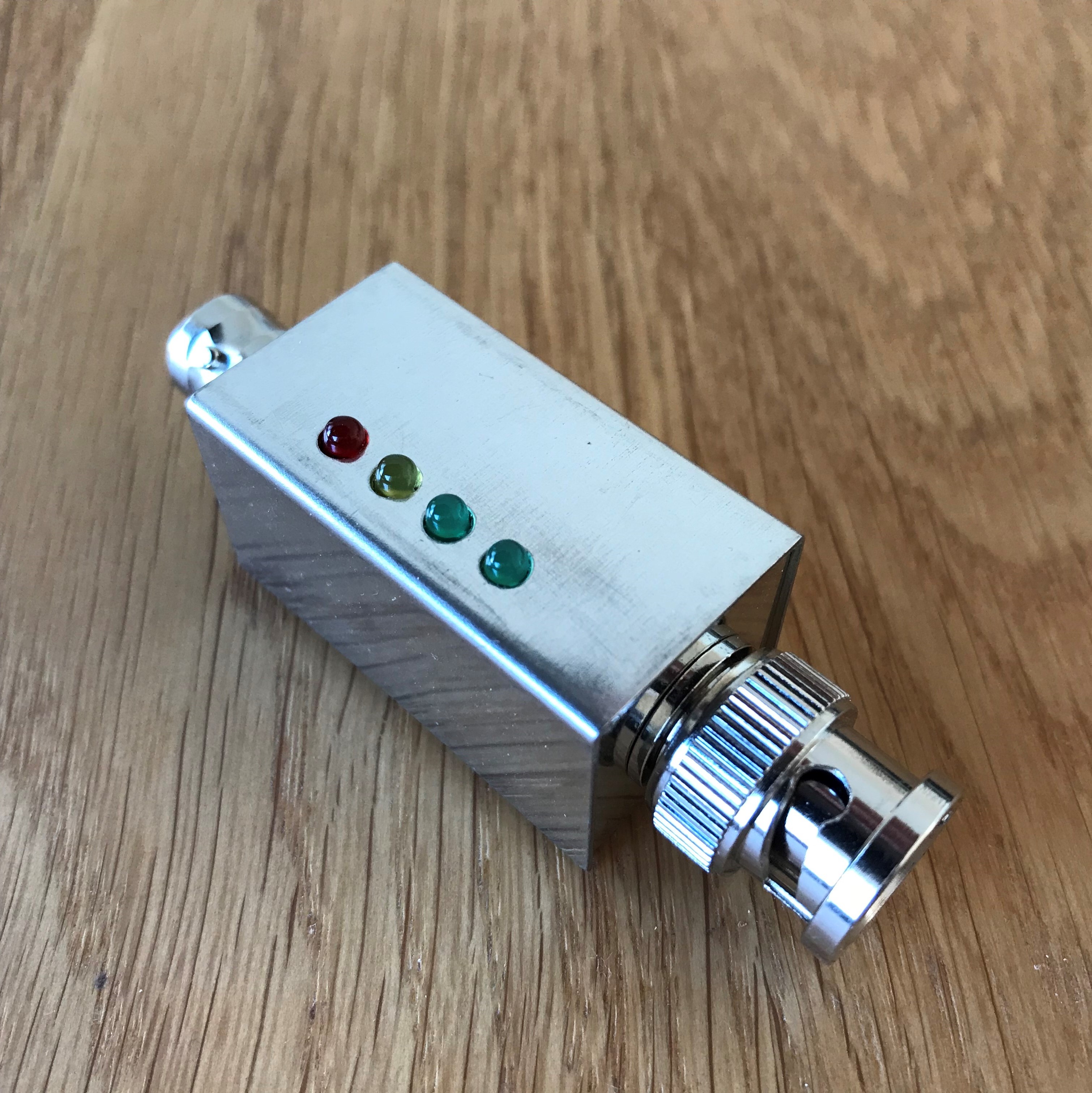
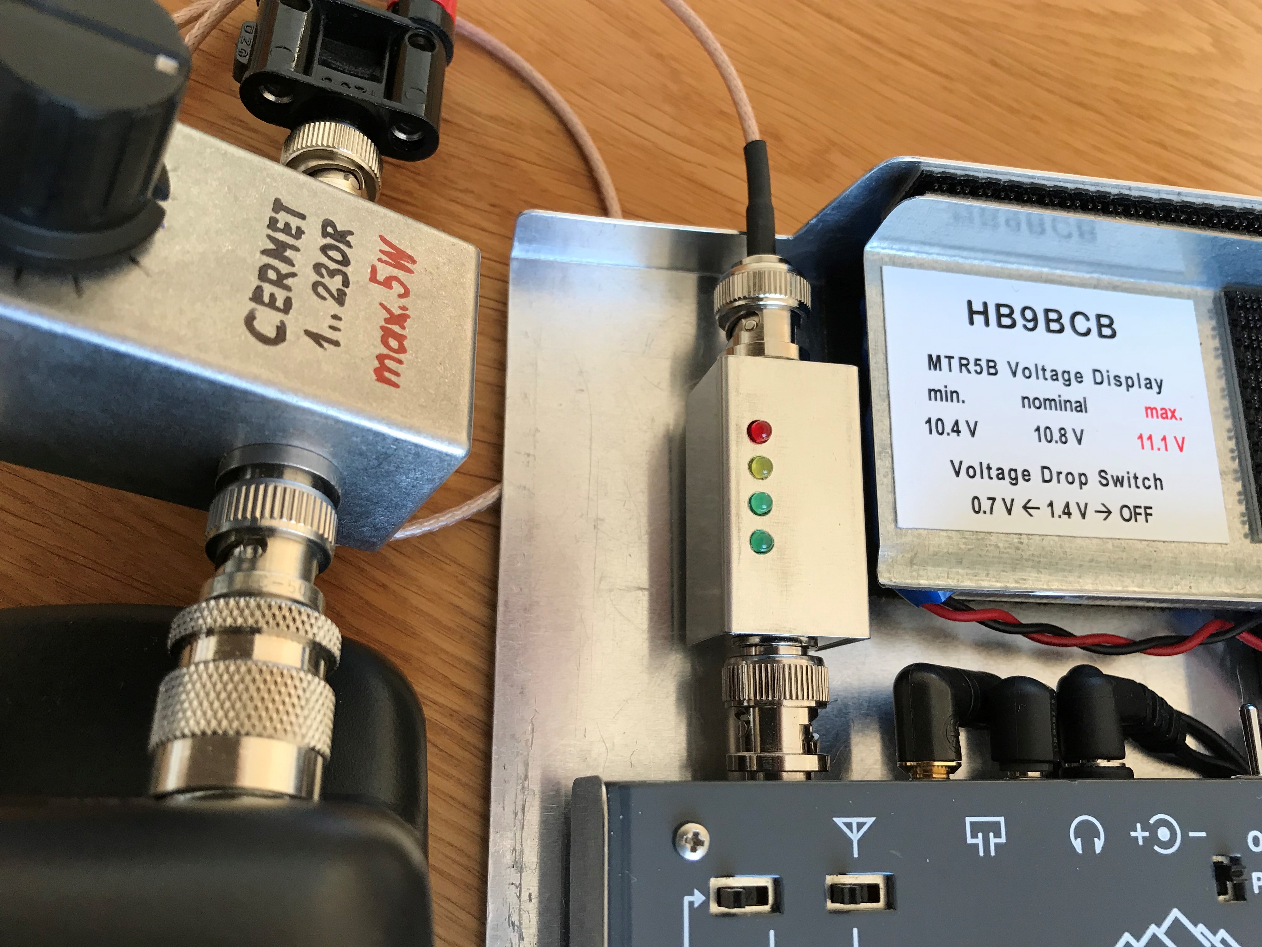
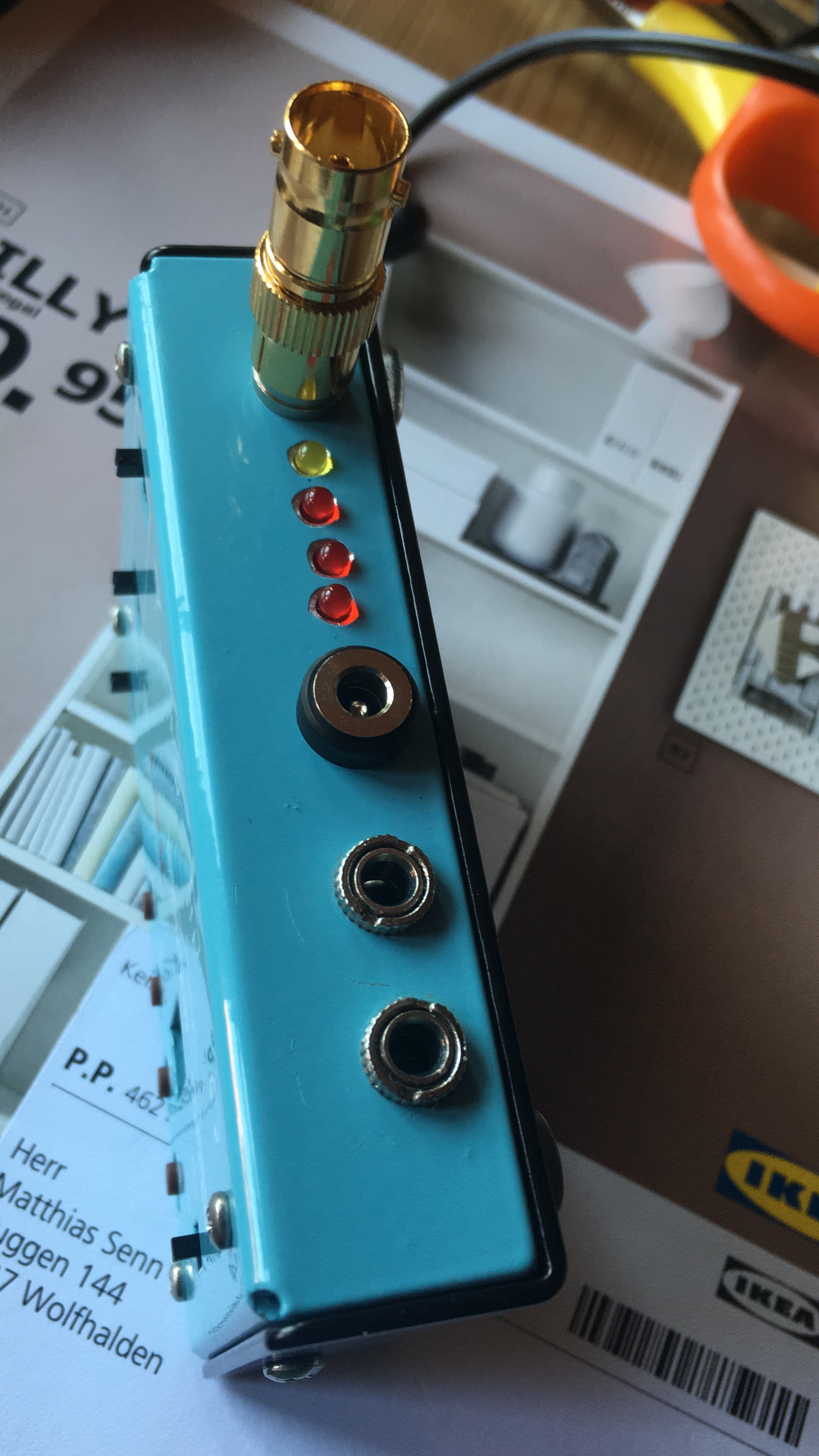
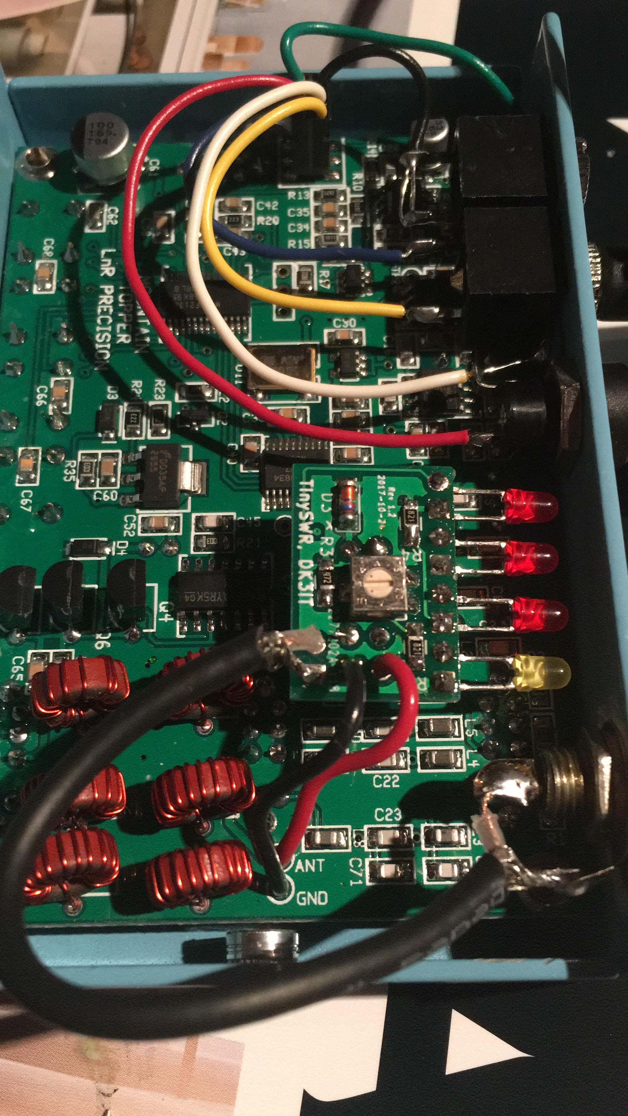
Another (slightly customized) TinySWR is ready and works as expected - not as a SWR Meter but as a SWR and RF Indicator - excactly as promised by the circuit developer.
Many thanks again, Martin@DK3IT.
My TinySWR should especially draw my attention if there is a real problem with the home made resonant antenna (trapped/linked EFHW) used together with the Mountain Topper Transceivers. That’s why I used different colored LEDs - the red LED starts to glow at antenna loads of: infinity, short circuit, <= 20R and >= 125R (SWR of approx. 2.5). The yellow LED starts to glow at <= 33R and >= 75R (SWR of approx. 1.5).
Modifications made (all the LEDs are low current types from Knightbright):
R4: 680R
RF1, SWR1: green LED (1.9V)
SWR2: yellow LED (1.85V)
SWR3: super red LED (1.7V)
The filter housing FG1B 37x20x20 mm used is very tight …
http://www.box73.de/product_info.php?products_id=2887
… the next larger FG2B 50x20x20 mm may be better suited for less experienced builders
Dear Heinz,
thanks for the report and pictures! I am always impressed by the level of craftsmanship in your constructions!
73 de Martin, DK3IT
Hi Martin,
Here is your tiny SWR meter installed in one of my MTR-5B SOTA radios. The LEDs are a little dim but bright enough. All that is needed are assurances that the radio and the antenna are working properly, and this does it!
Thanks & 73,
John K1JD
Santa Fe, NM
Hi John,
thanks for the feedback and picture! As for the brightness of the LEDs: It will be better if you operate full 5 W from 12V. You can use my switchable 6-9-12 V DC-DC boost converter with input and output filters for that purpose:
Also, I am working on a fully digital version of the SWR meter with a tiny Stockton coupler and an ATTiny in SMD. It will be only slightly bigger than the current version but actually measure the SWR independent of the power level. But this is work in progress, will likely take until 2018 to complete the firmware etc.
hpe 2 cu on the bands one day!
73 de Martin, DK3IT
PS: I saw on QRZ that you are a fan of the MTR-5B - maybe this all-in-one GoBox project is interesting for you: New SOTA Station Design: Mountain Topper Go Box and TinySOTA
Dear Fred, sorry for my slow reaction: I do not have the exact types from Barry’s list at hand, but basically most 2 mA versions should work fine, and even some standard bulk 3mm LEDs will do. Really critical is the OSRAM SMD LED on the PCB, because most other SMD LEDs in red have a significantly higher forward voltage.
Martin
Barry kindly sent me a board to play with…
? What gauge magnet wire should I use on the torriod ??
Richard // N2GBR
Hi Richard,
for the secondary winding, use ca. 30 cm of 0.2 mm enameled wire 0.2 mm. For the primary, I now recommend using simple insulated wire, because burning of the insulation from such a short piece of magnet wire with precision is a bit challenging.
0.2 mm is ca AWG 32 (see AWG to mm2 | Gauge to mm conversion).
The exact diameter is not very critical, but thicker wire may not fit evenly on the tiny toroid.
Hope that helps!
73 de Martin, DK3IT
Thanks… Martin… visiting the company R+D lab this week (I work from home)… so its a good time to pick up a couple of items for home electronics projects… and that’s something encouraged by the company I work for… they like us to have home electronics projects!
Richard // N2GBR
FYI: I found another page with simple QRP SWR indicators, maintained by JA1XRQ:
http://ja1xrq.g.dgdg.jp/SimpleSWR/SimpleSWR1.html
He partly uses the circuit that is the basis of TinySWR and has some hints on ideal resistor values for varying power levels.
The page is in Japanese, but Google translate is your friend ![]()
73 de Martin, DK3IT
Hi all,
Ondra, OK1CDJ, is now offering a complete kit of TinySWR:
For EUR 5, you get the PCB and all parts, which is a really fair price.
Thanks to Ondra @OK1CDJ for this great service to the community!
73 de Martin, DK3IT
Well done Martin @DK3IT and Ondra @OK1CDJ.
I bought 4 and very happy with testing so far.
73 de Pedro, CT1DBS/CU3HF
Hi Martin
I ordered the kit from Hamshop for about three weeks. It is the perfect accessory for the Monutain Topper MTR3!
Many thanks to Martin and Hamshop!!!
vy 73 de Matt HB9FVF
Can you please post the link?