The Xiegu G106 thread

Mic update 1.0:

After having to repeat my call sign (again and again) to various stations… I decided to do a bit of work to sort the fist mic out.

Reports: “muffled sound”, “bassy sound”, “narrow modulation”.

Furthermore, the ‘mic gain’ setting in the menu did nothing to alter the volume or the sound.

First thing of note - the included fist mic is a cheap, basement bargain, generic thing.

I doubt these are produced consistently. How can SSB be modulated if the fist mic components aren’t quite up to spec?

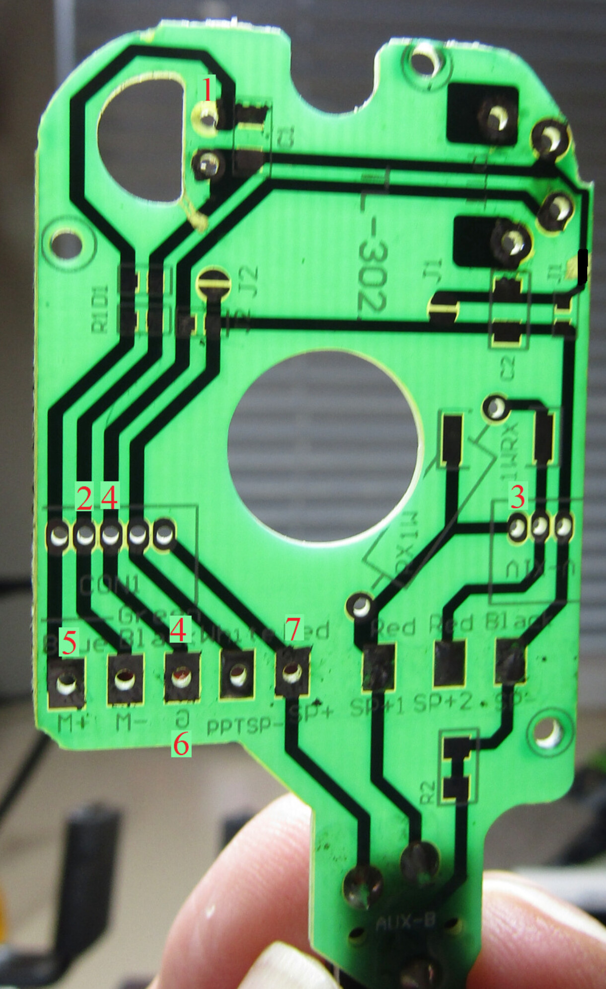
A decent maufacturer will set the electret sensitivity with a bias resistor, and the frequency response set with a capacitor. The only relevant components inside the fist mic are the electret and capacitor - so those are the only things I can change.

  1. Mic hole:
    With reports of a muffled sound, I decided to drill a hole into the housing to allow sound to travel to its intended destination.

This made the sound less muffled, but the frequency response was still bassy.
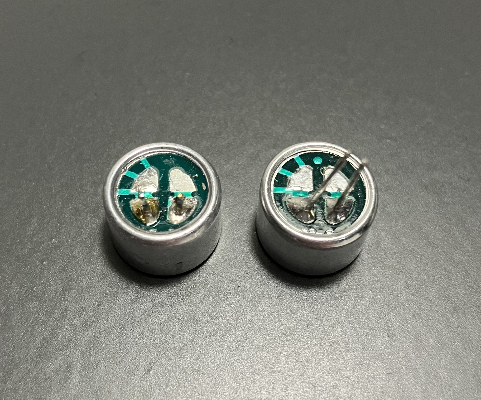
  1. Electret:
    It’s worth knowing the intended specs of the electret. Why is this important? To know what to replace it with, should you wish to install something better. It could be 1 kohm, 2 kohm etc… and changing the electret can alter the sensitivity (remember the bias resistor?).

I took a guess and installed a 1.5 kohm electret which I happened to have. That way, I know what I’m working with.

This didn’t’ change the audio level / frequency, or allow any mic gain adjustment.
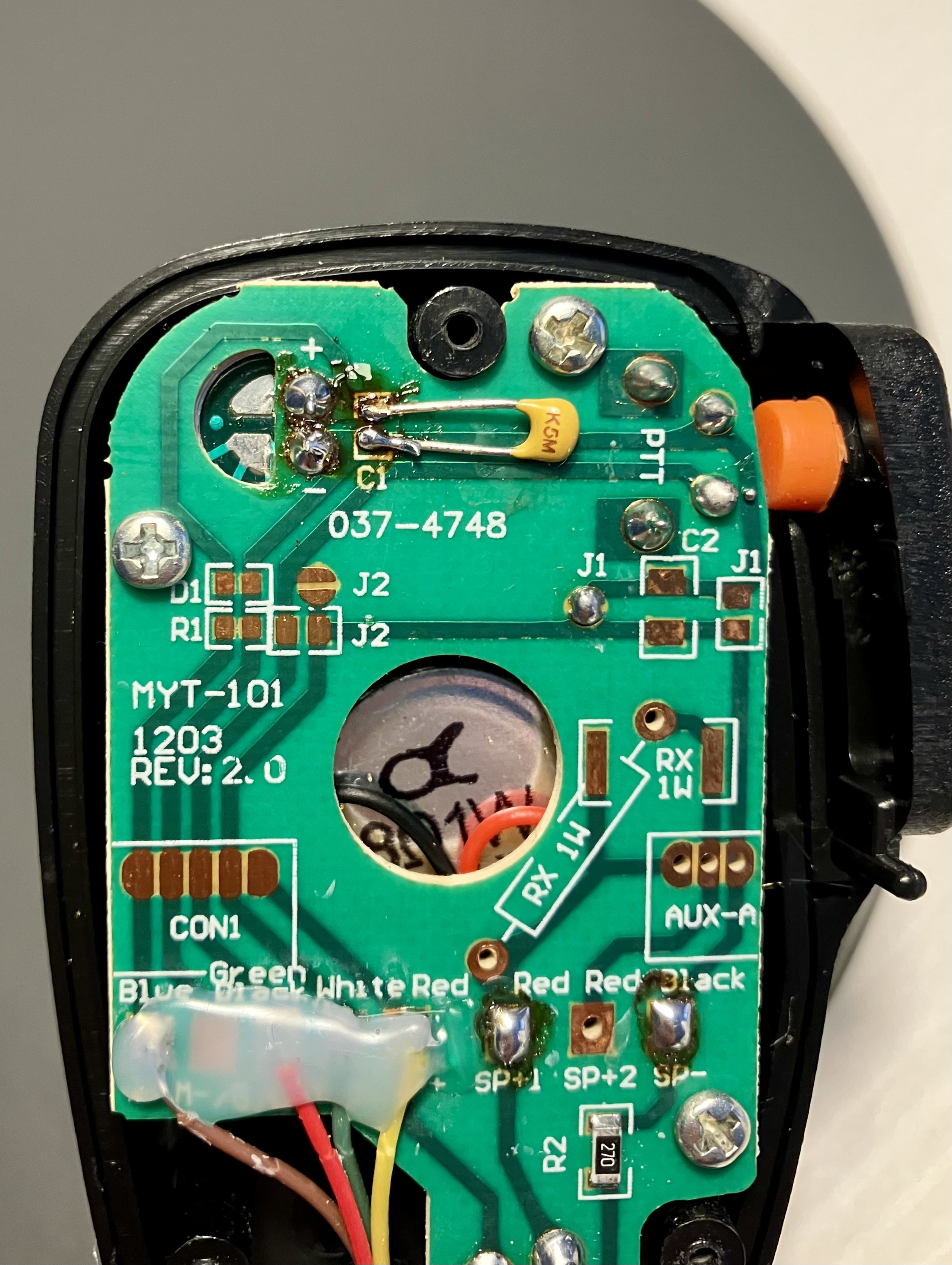
  1. Capacitor:
    There is a bleed capacitor C1 right across the electret. I removed it to measure the value - I could not get any sort of measurement off it. I wanted to know the 3dB point of the stock filter but failed. EDIT: This has since been measured - it was in the pF range, not the nF range. It was nowhere near the right value to start off with.

Regardless, the equation is: f=1/(2piR*C), where R here is going to be 1.5 kohms. This is the low pass filter, and we want the 3dB point to be right. Reducing the 3db cutoff reduces treble. Increasing the 3dB cuttoff point increases treble. I figured C1 should be around 10nF.

After installing a 10nF capacitor, the audio had more treble. :ok_hand:

More importantly, the mic gain setting now actually works. Quiet at 0, progressively getting louder upto 30. There was bit of clipping at 30, but I was speaking loudly (not shouting) close to the mic.

So far so good. I’ll report back after making more contacts / adjustments. :crossed_fingers:

2 Likes

The cap across the cartridge wasn’t there to shape the audio - electrets are infamous for allowing RF ingress, so it was there to stop that from happening. So, if you were able to goose it up in value and get some audio shaping whilst still RF-proofing the mike input, that is a win! VK4TJ.

5 Likes

Thanks for chipping in.

Other oddities observed (pre-modification) might point to RF getting in through the mic/cable.

The curly mic cable doesn’t appear to be shielded - something else I might investigate. :crossed_fingers:

Update:

I’ve done some digging - seems the included fist mic is a bad clone of the Yaesu MH-34B4B (which has been superseded by the SSM-17A).

Ali express/ebay sell these clones touted as the MH-34 and… they use the same circuit board.

The board has various pads/holes for use with different radios - depending on how they work.

So the G106 does indeed come with the cheapest fist mic going. Not only that, the curly cable lacks any shielding.

2 Likes

Lack of shielding:
So here’s what the stock mic cable consists of. Interestingly there’s a black wire, which wasn’t connected to anything at either end.

Appropriately shielded cable?
I got hold of a cable with shielding of sorts… but is this enough? The plan, would be to use the red wire for the electret as it’s covered with braid. Problem - I’ve been advised not to connect the shield at the mic end, and only at the radio end. The thin, uninsulated wire has continuity to the braid so I can’t use that separately.

@GM4LLD - would that work, or should I just get another cable?

1 Like

Hi Omar,
I going to stick my head out here and say the shielding has nothing to do with your issues.

Many of these reasonably priced chinese SDR radios have issues with conducted immunity.

I am pretty confident it’s not radiate immunity picked up on the cabling. I have tried shielded and unshielded RJ45 cables, both work. I have just three simple wires - condenser mic and a K6ARK case - Works great, in fact my go too mic!

I suggest you try a decent choke first, to stop common mode current in its tracks - on the antenna feed and then re-assess!

Hope this helps!

3 Likes

Thanks Tim - I’ll certainly be making a choke.

Based on what’s arrived in the post so far, the order will be:

  1. Cancelled (Finish adaptor).
  2. Cancelled (Test Yaesu headset).
  3. I’ll get the speaker mic re-wired (with shielded cable).
  4. Test the speaker mic to see if shielding makes any difference on 20/10m.
  5. Choke.
  6. If all goes well, a tiny backup mic.

Problem is, activation QSOs are short - I might have to ask a DX station to hang around for some tests/comparisons.

EDIT: Cancelled items are due to the way in which PTT works on the Yaesu headset that I have. It works by detecting the line has been grounded though a resistor, rather than using a dedicated PTT wire. I’ll find a different headset.

1 Like

Don’t forget that the Headphone output is only on the mic. not the radio, so if you use a headset, fine but if you want to use headphones (or ear buds) and a small mic, you’ll need to have a socket for them to plug into, off the RJ9 lead.

73 Ed.

2 Likes

Thanks Ed - the idea was to use it as a backup combined with the main speaker… but I suppose you’re right - it’s better put a headphone jack on the backup mic so that it can be used either way, regardless. :+1:

1 Like

I think that Tim is right. I would try a choke before anything else. A FT140-43 toroid does a decent job.

If you’re near Cardiff you can borrow mine for testing

Cheers,
Kevin

2 Likes

Thank you - very kind!

I don’t mind making one of my own… but I suppose if I’m passing, I may as well try it.

3 Likes

Omar, where is the counterpoise in your system?

1 Like

It was suggested that due to the length of coax I was using (4m)… there wasn’t a need for a counterpoise with the particular antenna I am using. :man_shrugging:

I’m very keen to test different things (counterpoise, ground, choke, battery)… one at a time.

A station (or two) on 10m willing to test/figure things out with me would be fantastic… but I I think I need to be on a summit (home QTH isn’t great).

Feedback from @W4GO :

Yesterday, @SQ9IDE reported an audio/modulation issue on 10m.

I’ve had an EA station suggest I check my battery (modulation issue) but I can’t remember what band.

On the Trans-Atlantic day (on 10m), a UK station whom I know worked me whilst on the summit , and reported an issue. I switched to medium power - the issue was still there, but to a lesser extent. I also changed the radio’s position relative to the antenna.

This station suggested that RF might be getting in from the mic, hence I changed the cable. At least now I know my issue is only on 10m (nobody complained on 40 or 20m on the last activation.

I’m happy to head to my local summit (Staple Hill) and take a load of stuff with me (including a lead acid battery) to work one or two willing stations who might help identify what it might be. :crossed_fingers:

1 Like

No counterpoise means the outside of the coax to the antenna is hot with RF especially if you haven’t trimmed the radiator length.
Add a counterpoise to reduce that current.
Fit a common mode choke at the radio to reduce that current further.
Use a screen cable for the mic and any other signals.
Decouple the the PTT and Mic inputs with 1nF…10nF caps on the back of the connector on the PCB.

3 Likes

Thanks Andy:

I’ve trimmed the radiator to get SWR as close to 1:1 as possible on 40m (but it changes depending on where I set up). *Done (I think).

Screen cable added for mic (the braid only covers the mic+ unfortunately, but it’s more than what it had before i.e. nothing). That braid is being used as ground. Happy to go further with this. *Partially done?

Electret originally had an SMD capacitor circa 500 pF, and I’ve replaced it with a 10nF cap (not SMD) instead. PTT hasn’t been touched, so I’ll look at that (also happy to get a 10nF SMD cap to get rid of the legs if need be). *Partially done.

Easy to add a 2m bit of wire (I assume this needs to be relevant to longest wavelength I’m operating on hence suggesting 2m and not 0.5m)? *Will do.

Choke. *Will do.

2 Likes

Decoupling capacitor has to be at the rig socket end. How long is the counterpoise? It depends. Try 2m,4m,5m and see what happens.

2 Likes

OK - so the capacitor I was fiddling with (with the intention of audio shaping and gain control) is irrelevant.

I can make a small adaptor (RJ9f to RJ9m), with the caps in there for starters - will that do? Easy to plug it in-line with the mic for testing,

I’ll get various lengths of counterpoise made up.

Thanks again.

1 Like

It’s a good place to start and it means you wont be taking the radio in and out of its case repeatedly. That always leads to breakage somewhere!

2 Likes

Photos of the G106 internals are here if anyone is interested:

https://fcc.report/FCC-ID/2ANLH-G106/6050076

2 Likes

This is exactly what amateur radio is about.

Have you tried a choke yet?

If you don’t have a counterpoise and you don’t have a choke then there will be current on the outside of your coax and it will go straight into the radio. A choke will stop that. Without a counterpoise and choke I think you are wasting your time on the microphone.

2 Likes