III) Step by step construction of the 2BD antenna
Step 1, Wire elements
First I cut the wire elements at home. A tough work to deploy and measure that in my small apartment! I used a very lightweight but strong wire from Sotabeams (thanks Richard and crew, it is not easy to find a cable like this one).
I cut the initial loop lenghts a bit longer as I expected I would need to trim the dimensions to get the right resonance of them; I preferred to be safe and don’t start with a resonant frequency higher than 14.350 MHz.
-
Initial Driven loop perimeter: 22,50 m
-
Initial Reflector loop perimeter: 23,60 m. Remember I will trim these lengths later to fine tune resonance. See result on the Test chapter (IV).
Step 2, antenna guying kit
- Corner plates:
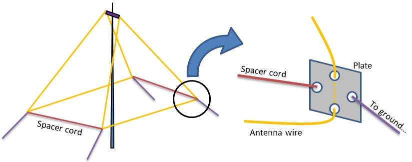
I designed a small plate to hold the guying cords in the corners of the Deltas.
In order to warranty a 4 m space between the driven and the reflector loop, I added a 4m spacer cord that would be tied in this plate. I prepared this design:
I made 4 pieces with plywood, and used an acrylic paint to protect it:
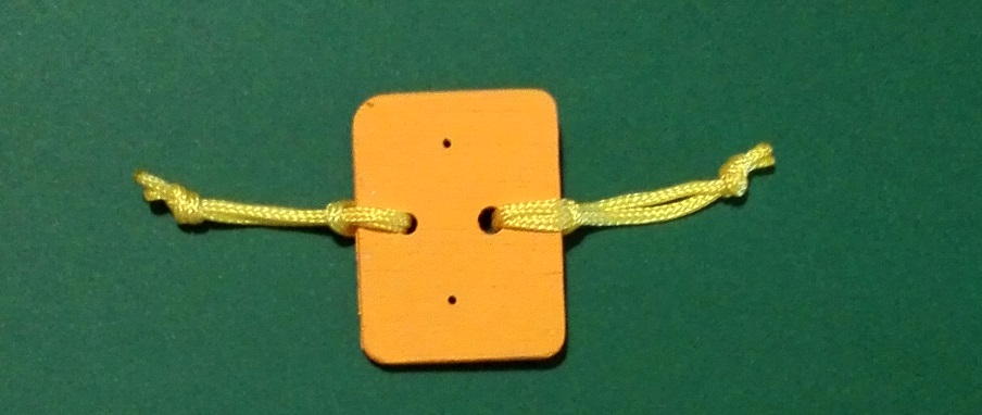
Note the small holes for the antenna wire passing through and the 2 yellow cords to tie the ground and spacer cords.
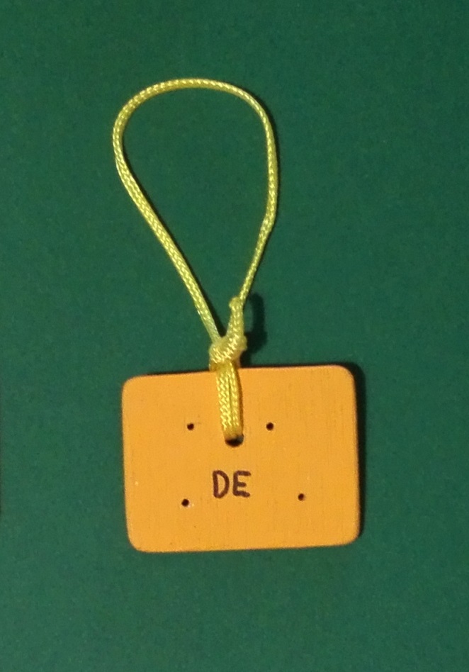
- Top plates:
I prepared 2 similar plates for the top of the Delta (one for the driven , other for the Reflector). See a picture here:
Note the holes for antenna wire and the top short cord to hold it from the boom.
After testing the antenna now I’m ready to add a connector for the coaxial cable. I will use a RCA that is light and ok for low power.
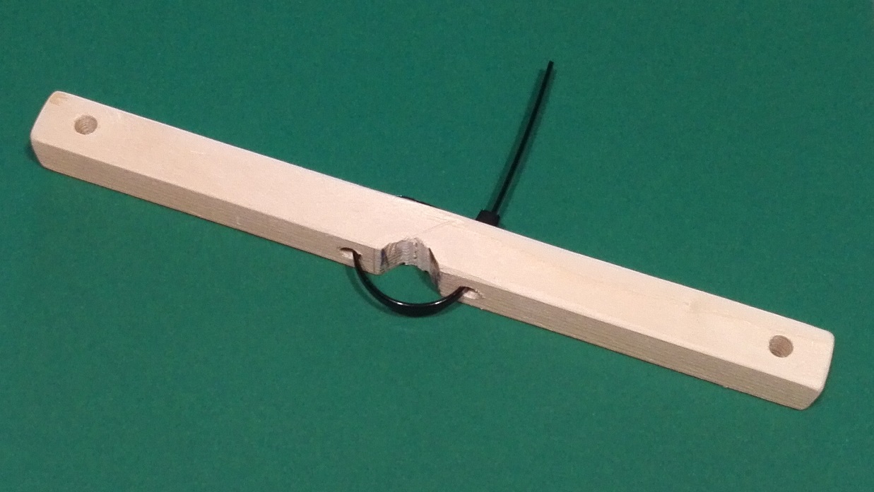
- Small boom:
As explained, the appex of both deltas are closed together. I prepared a small spacer with a square dowel 24 cm long. I drilled two holes to tie the top plates and also 2 holes to pass a nylon tie to clamp the boom on top of the pole. Picture attached:
Step 3, Coaxial
As explained, the impedance is near 50 ohms. I decided to add a choke near the feed point.
I prepared it by winding 15 turns of RG-174 (small diameter) on a toroid Ferroxcube TX36/23/15 - 4C65 (similar to Amidon material 61). The length of this coax is about 2 meter long with the choke near the feeder.
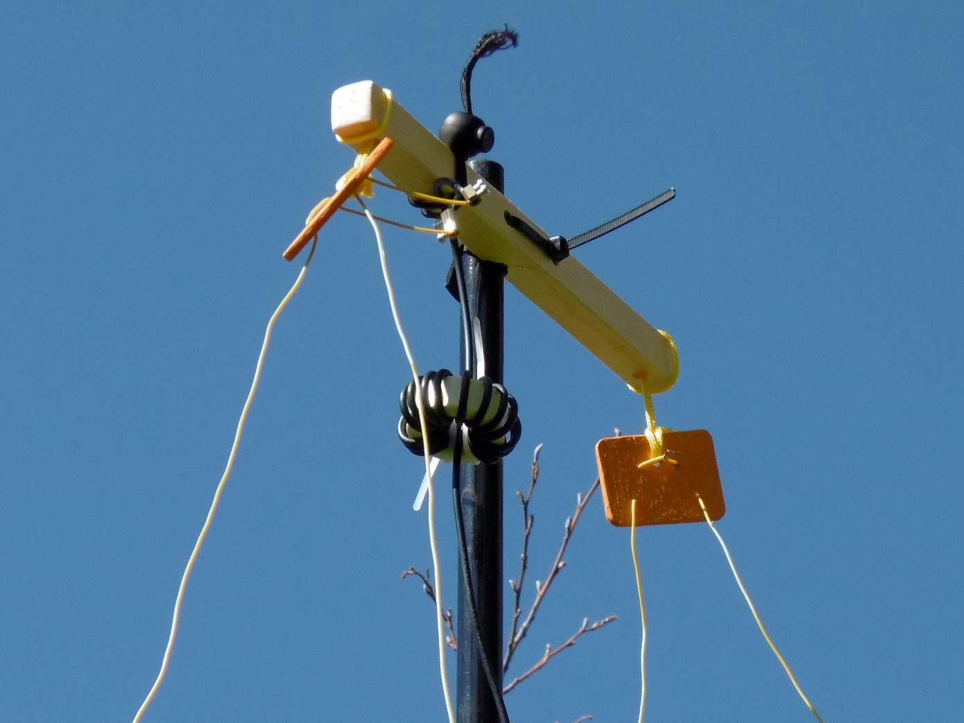
See how the coaxial, top plates and choke looks when assembled with the antenna under the boom:
Then I added another 7 meter of RG-58/U to extend it downwards along the pole.
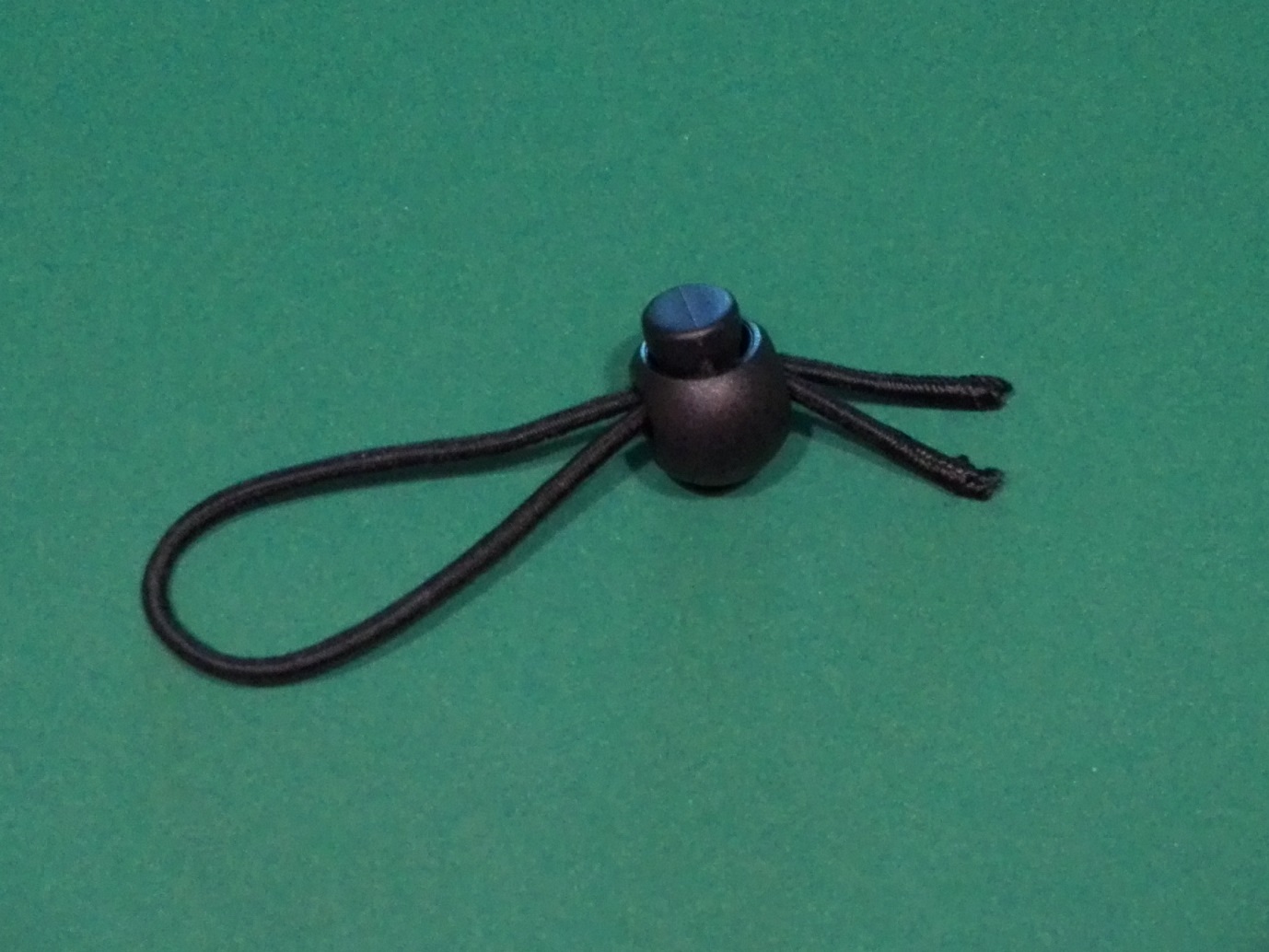
The coaxial, is hold to the pole using elastic cords and plastic cord locks:
IV) Antenna testing and trimming
Everything was prepared. This is the completed material ready to be tested the first time:
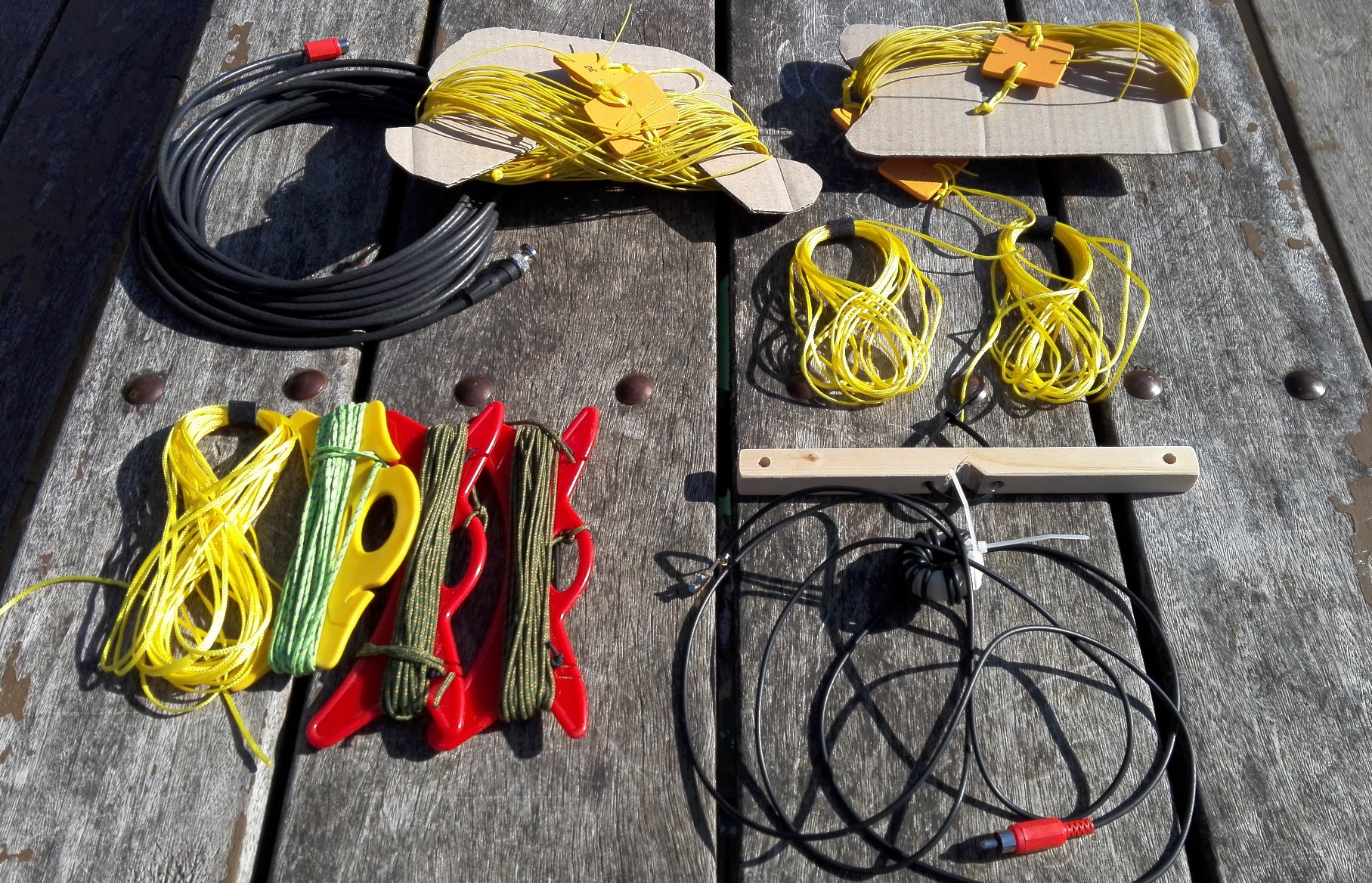
Looks like a lot of parts but I keep anyone in its own zip bag and it is easy to install it.
And here the antenna erected at low height:
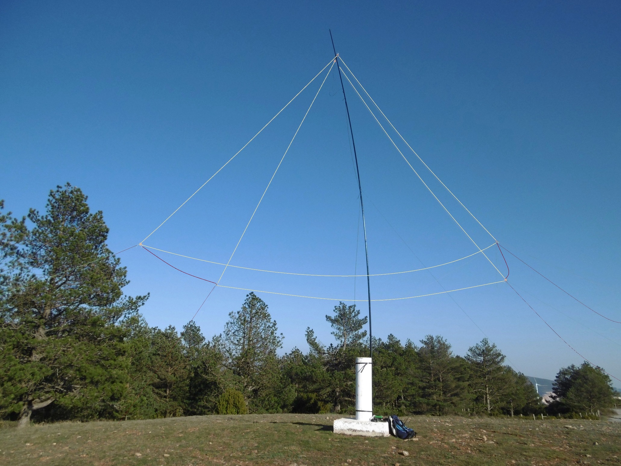
First trial of the antenna was fine, the antenna analyzer was happy with the antenna, producing a deep resonant valley at 13.130 MHz. I knew that would happen… SWR was 1:2, so the impedance was confirmed to be all right!
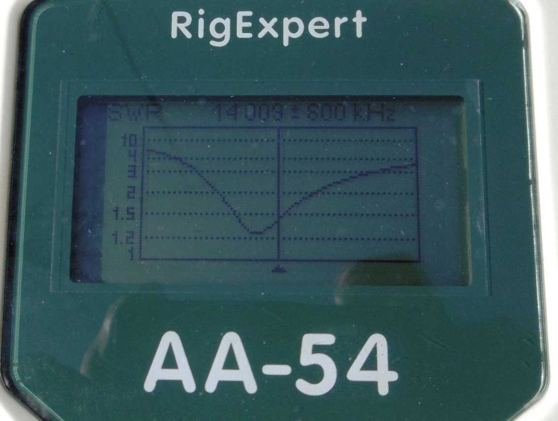
I trimmed both wires and got the resonance near 14.000 MHz. See the SWR plot:
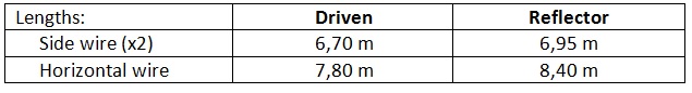
Final Loop dimensions:
-
Driven loop perimeter: 21,20 m
-
Reflector loop perimeter: 22,30 m.
See the distribution of the wire on the three sides of the triangle:
V) Conclusion
Well, it is rewarding when you have an idea, you make a real model and see that it works. When you are done and see that beatiful shape on air without falling down you feel relief and satisfaction.
Now it is time to do some more testing and comparison in future activations.
I know it is not a multiband antenna and that it requires some more time to set up on a summit, but is is an antenna to be used in special events or even in some Field day contests.
A variant for another band can be done easily.
Is there any room for improvement? Sure, what about adding a director now? Maybe in summer time…
Please let me know if you copy my design and make a replica. That would be just perfect.
I think I’ll send this article to some amateur magazines, it does worth sharing interesting ideas.
73 de Ignacio