Summary
I designed a light portable 2 element Delta beam antenna for 14 MHz. The target was to have some gain over a dipole and directivity. I released version 1.0 of this monoband antenna and published its first test here
The 2BD antenna is born. I still need to develop some more tests but in the meantime I want to share some details in case you are interested and want to build yours. Here we go.
I) Design
I wanted to have an antenna with the following characteristics:
- 14 MHz was the target frequency
- It should be a variant of a 2 element yagi to have some gain over a dipole
- I would prefer a 50 ohm direct feed antenna
- a single vertical support pole should hold it, plus some guying cords
With all this in mind I started to plan what kiind of antenna I could build by myself.
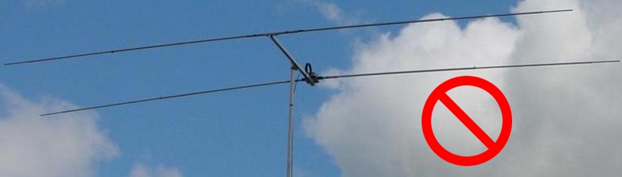
Installing a standard yagi on a pole was discarded immediately, because it wouldn’t be possible to stretch the wire elements horizontal over ground, as I wouldn’t have rigid elements, because they add weight:
Then I started thinking to find alternatives. Let’s see the main ones I thought.
Idea A) I could install a modification of a 2 element wire yagi placing the elements inverted vee as for sketch A. This is used by operators on Field day events.
Idea B) A 2 element wire moxon was evaluated because it is a bit more compact in size. I checked feasibility of installing inverted vee, as for the case A. See sketch B.
Idea C) A 2 element delta loop was also in the list, as shown in sketch C.
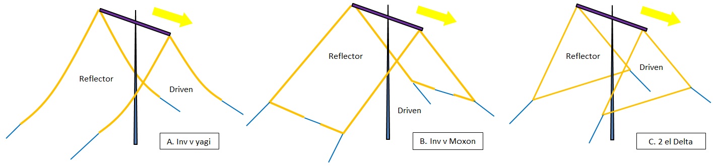
(wire lengths not to scale)
Although all these ideas were basically valid, I didn’t like the long spacer (boom) on top of the pole, where the diameter is the weakest part of this support. I wanted a more equilibrated system. Having this long spacer on top would add weight and most probably the pole would bent; this would be even worse in case of high wind.
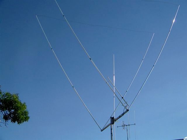
Concerning the idea C, I couldn’t find any picture showing this configuration. I just found this variation where the Deltas are 180º rotated and the spacer below:
This desing wouldn’t be possible for me on a mountain top, but I the decided to find something different with the two Deltas. Their performance has a good reputation: low noise, some gain over a dipole and they work well at low height over ground.
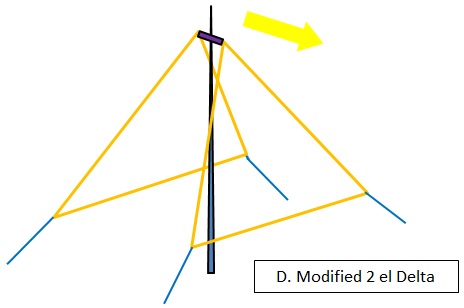
I was thinking how to improve that and then I had one idea: what would happen if the boom was replaced by a short spacer, say of 20 centimeter long? That would transform the system this way:
I understood this could modify the performance in many ways, affecting to Impedance, Gain and radiation pattern., but the concept was interesting and I decided to try a number of models in a simulation software (Mmana) to compare and optimize its dimensions. Let me show the evolution of the model until I reached my preferred version.
II) Evolution of the 2BD antenna design
I proceeded trial and error, following many steps.
1.) Simulation of a reference dipole inverted vee up at 9 m above ground.
Target: to state the reference values for Gain and pattern
Result:
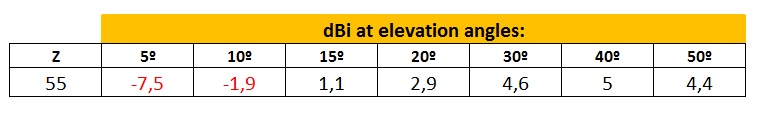
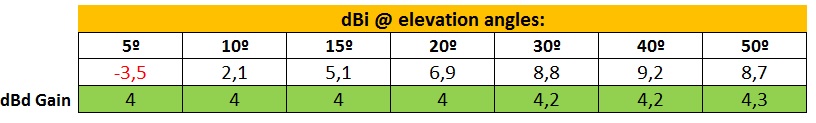
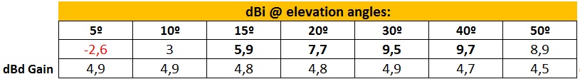
I studied the gain achieved at different elevation angles, table is included here:
2.) Simulation of a 2 element Delta according to sketch C
Target: to find the optimum distance between two parallel loops to get the best Gain and pattern over the reference Dipole.
A standar yagi has the Driven element cut to the desired resonant frequency and the Reflector about 5% bigger in size. The space between both elements is about 0,15 to 0,25 wavelength.
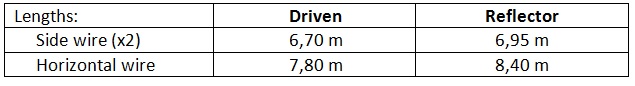
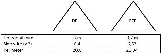
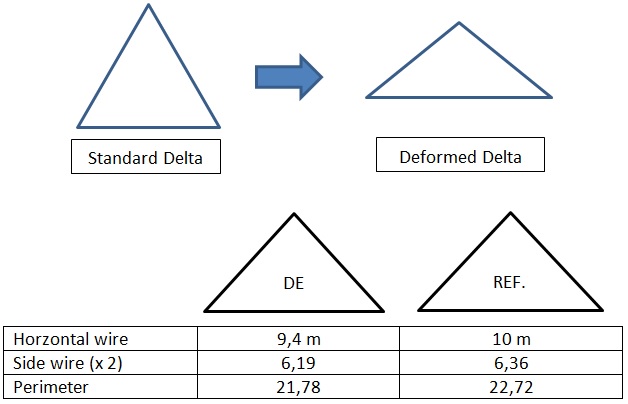
Dimensions: instead of a regular equilateral triangle I enlarged a bit the horizontal wire and reduced the same amount to the side wires, in order to have the Delta further up above ground. These are the simulation dimensions I used:
Result:
I ran several models with the space varying between 4 and 6 meters. Difference in performance was small and I decided to choose a space of 4 meters between the loops.
See the table with gain (comparison with reference Dipole included below and shown as dBd):
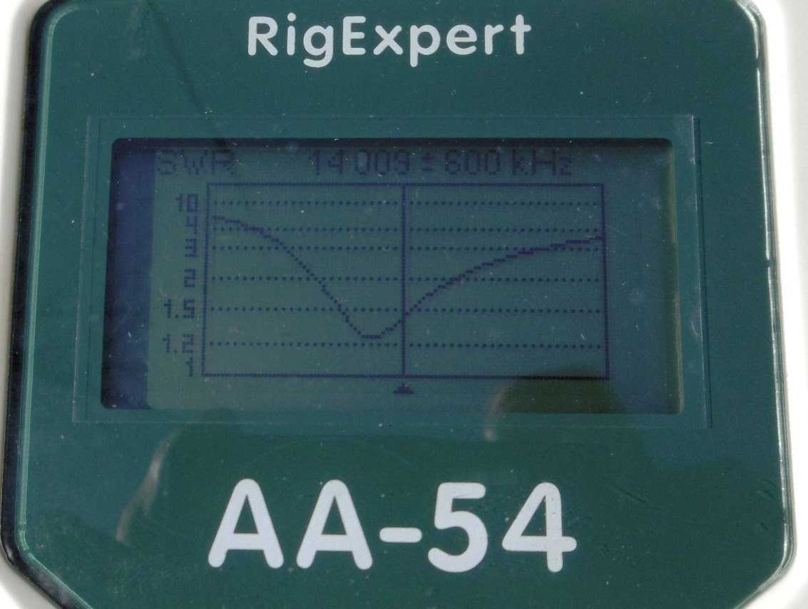
Resonance was at 14.500 MHz (I should increase the Loop size in the next model…).
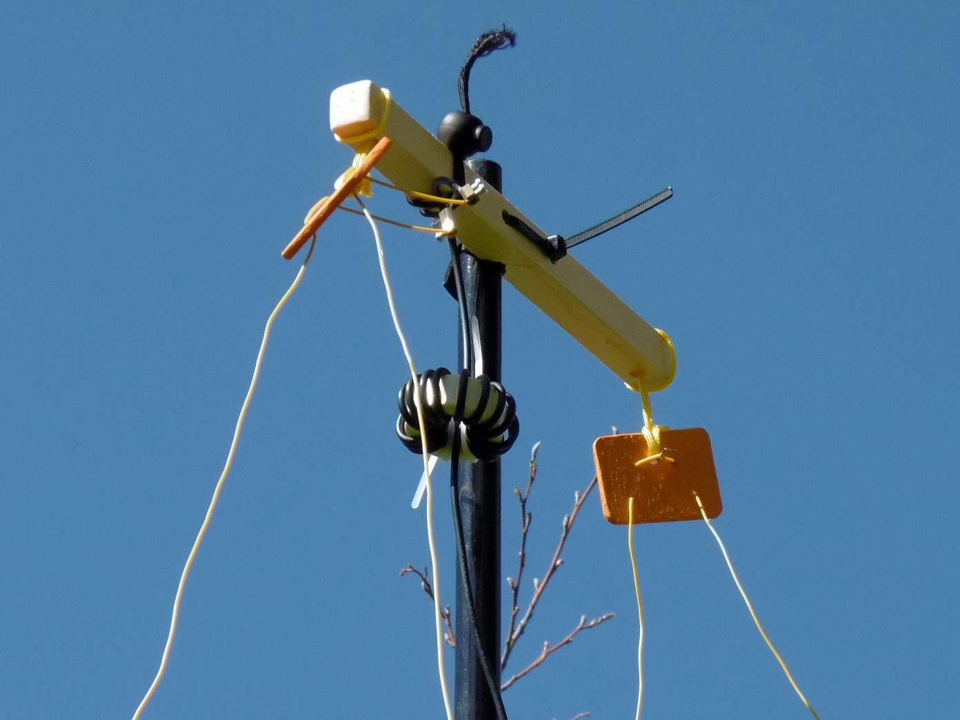
The resulting impedance was the one expected for a Delta loop, Z=113 ohm. Feed point was in the top appex, that is the best point to avoid weight that pulls and deform the Delta wire.
Here you have an azimuth diagram comparing the patterns of the Dipole and the 2 element Delta at 30º elevation:
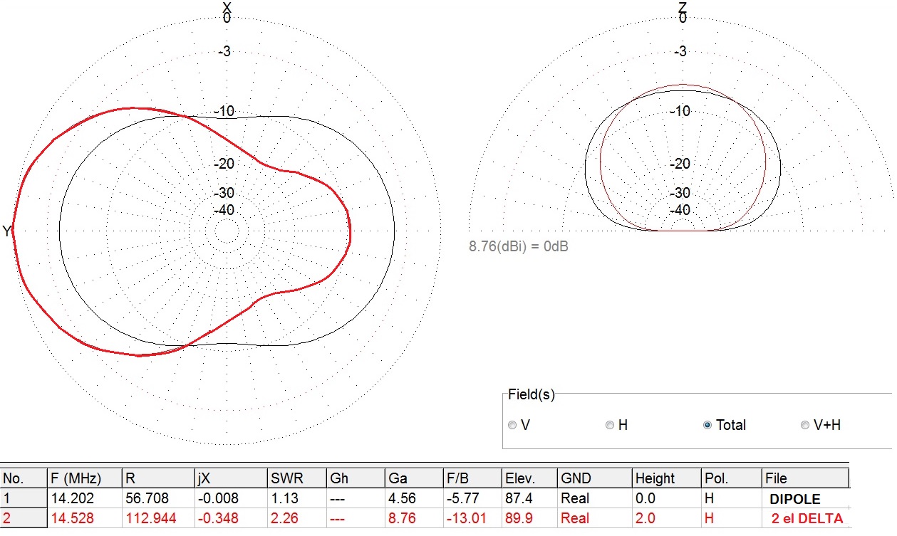
The results were promising: 4,2 dBd at 30º elevation (8,76 dBi – 4,56 dBi = 4,2 dBd) and the tipical pattern of a beam antenna!
3.) Simulation of a 2 element Delta according to sketch D (the 2BD model)
Target: to check if moving both appex towards the holding pole would affect the results. I displaced both points to simulate my design, according to sketch D, having a space of 20 cm between both appex.
Result:
The effect of bending the loops had a very positive effect on the impedance; now the model had 46 ohm! With this change I could feed the antenna using standard 50 ohm coaxial cable.
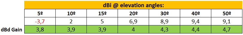
In the other hand, the gain was quite stable; only a small reduction of gain was produced at very low angles, that is, a negligible reduction of 0,2 dBd at 5º elevation.
4.) Optimisation of the Loop shape to increase the Gain
Target: to get some more gain by modifying the shape of the Loop, by moving the horizontal wire further up to be higher above ground, making the loop more like this shape:
Results: see the effects of this change here:
By changing the shape factor now the gain would increase about 1 dBd at low angles , not bad.
It sounds well, but in praxis, it is not realistic having these long horizontal wires straight , because their weight make the wire bends towards ground and we don’t have a triangle anymore, decreasing the overall height over ground of the resulting antenna.
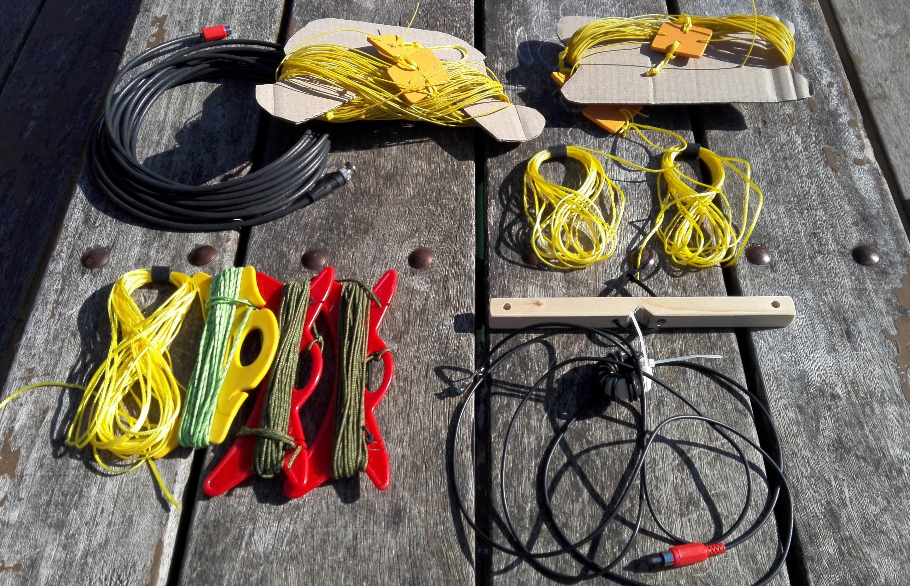
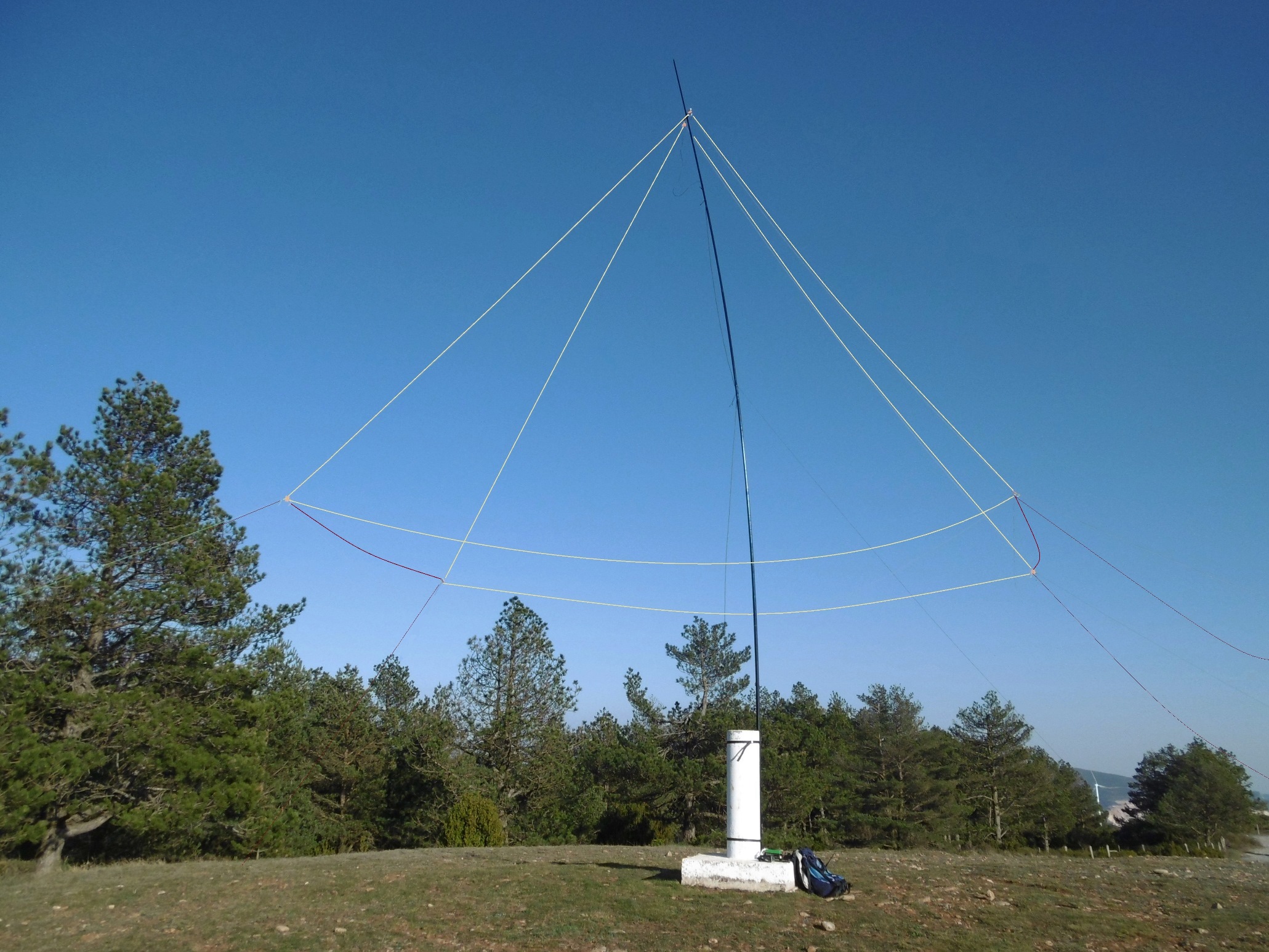
Therefore I decided to stay with model nr. “3 “ and build a prototype.
Article continues down…