Testing Antennas during an M5 Flare

Well the great thing about HF is there are an unlimited number of wire antennas that can be made for pennies. So I thought I’d try something new… a “random” 41ft wire with a 9:1 unun. OK the length is anything but random but 41ft is a good length with a 17ft counterpoise. Though enough time using metric measurements has resulted in 41ft being a meaningless number when it comes to length. So I worked out what 41 and 17 are in sensible units and then measured some wire. I had no idea if this antenna would be any good or not so the radiator and counterpoise are made from assorted lengths of “some yellow wire” with the pieces soldered together and insulated to make the lengths. Hey waste not want not. I made a double sided wire-winder out of a piece of estate agents sign as I am too tight to spend £3 on a commercial one. Mine was made from a piece of sign I collected for SOTA purposes after a storm in 2006… nearly all been used now. (Notes neighbour’s house is for sale… a possible source of a new piece of material :slight_smile: )

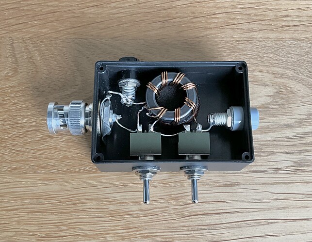
Also you need a 9:1 unun. An FT 114-43 core offered itself up as did some 24guage enamelled wire and thus a 9 turn trifilar wound coil appeared and was wired up. Except despite being on the way to 65 I cannot count and wound 8 turns not 9 :frowning: Anyway I applied a 470 ohm and 440 ohm (390+47) resistors in turn across the antenna connections and pumped it from the MFJ-259 and it said 1.2:1 up to 25 MHz and then 1.3:1 up to 30MHz. That seems to do what is needed.

The WX has been dire… when I could go and play and dire when I had to work. Today was the first decent day (currently 80% blue sky, gentle but cold wind and 18C) so off to the testing grounds… GM/SS-125 Scald Law. Now not having been up a hill since 31st May I was expecting pish performance but 44mins to the trig was OK. Fewer people out than I expected and considering the rains we have had, the ground was very dry. Go figure!

Up went the antenna as a sloping inverted L, about 4m vertical from 50cms AGL then sloping down to a 1m pole. The counterpoise was laid on the ground underneath the radiator. I pointed the sloping section NE towards Sweden. I need to look at the expected pattern to see how it should be setup. Then a 2m piece of RG58 connected it to the KX2. First job measure the match: 7.035MHz 3.6:1, 10.118MHz 8.3:1 14.03MHz 3.5:1, 18.085MHz 2.1:1, 21.06MHz 2.5:1, 24.9MHz 4.3:1 & 28.058MHz 3.7:1 All those values are handled with trivial ease by the KX2 ATU. OK, so does it radiate?

28MHz CW GI0AZB on GI/SM-005 and IU2BZ.
21MHz CW S5, DL, W4GO (for ODX), F
10MHz CW ON, F, G, DL
7MHz SSB G, F, MM
14MHz CW DL, OK, OE, I, OZ, OH
18MHz CW F, S5, I

Things didn’t sound right as there was even less noise than usual on a KX2 but Deutscher Wetterdienst on 10.1008 was unbelievably loud… S9++++++++ and there was huge amounts on QSB but 20m and 17m seemed to be giving very loud signals from Europe unlike the HF bands 21/28.

So it seems to function but is it better than other antennas? I don’t know but it’s coming with me to F/DL next week for the FN rally and we shall see.

Anyway I packed up and drove home avoiding being hit by the drunk in a BMW X3 who pulled out of The Flotterstone Pub car park without waiting for the traffic to make space… fin de cloche!

When I got back I found I was testing my antenna during an M5 Flare, here’s the summary

Space Weather Message Code: SUMXM5
Serial Number: 235
Issue Time: 2024 Jun 23 1326 UTC

SUMMARY: X-ray Event exceeded M5
Begin Time: 2024 Jun 23 1251 UTC
Maximum Time: 2024 Jun 23 1301 UTC
End Time: 2024 Jun 23 1311 UTC
X-ray Class: M9.3
Location: S18E70
NOAA Scale: R2 - Moderate

That would explain the general malaise of the ionosphere.

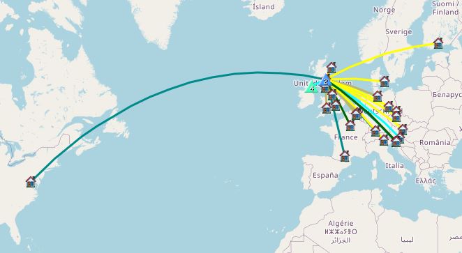
So is the antenna any good? Here’s a map of some QSOs made around the time of the flare. You decide.
41ft

9 Likes

Hmm, must make myself one to add to the HF antenna stockpile of 3 link dipoles, Slidewinder based vertical and 40m EFHW. Don’t know why I haven’t before now. :thinking:

1 Like

That was my thought… I have all the bits so why not make one and see if it’s any good. Spooled up and with its match unit it weighs only 110gm. As long as you have an ATU with you, you have a antenna that works from 40-10m.

It only cost me my time, some solder, some hotglue and an old used BNC socket recovered from something years back. As I said I even used assorted offcuts of wire to make the antenna. My sporran remained firmly closed the whole time. :slight_smile:

3 Likes

It’s always a problem to get low VSWRs on a multi-band wire antenna especially with 60m. Thank goodness for the KX2’s internal ATU. I had great success with my homemade (heavy duty) EFHW for 40m but of course I could cut the length to suit my favourite operating frequency.

But I wasn’t prepared for what a difference it made having it raised by a kite instead of the usual 6m pole. Signal reports given and received were stunning. I reckon it would do well on other bands too (with help from KX2). With this lovely weather, what am I waiting for?

2 Likes

As far as 15 m, I’d say it’s fine. This morning, I worked five EU summits including yours on 15 m CW, plus one each on 17 m CW and SSB. Your signal strength was basically the same as the others worked. Better than a couple EU summits which I could just hear, not copy, on the same bands on CW in the same time frame. Didn’t listen to you on 18 MHz.

My chasing this morning was before the flare. Prop wasn’t great but frankly about typical for the past few weeks.

3 Likes

Thanks for the interesting report Andy, and thanks for the following info. I was attempting to make some contacts on 40m this afternoon from GI/MM-005 during this time period and really struggled. Good to know that external forces might have been at work! :fire::fire:

2 Likes

Andy,

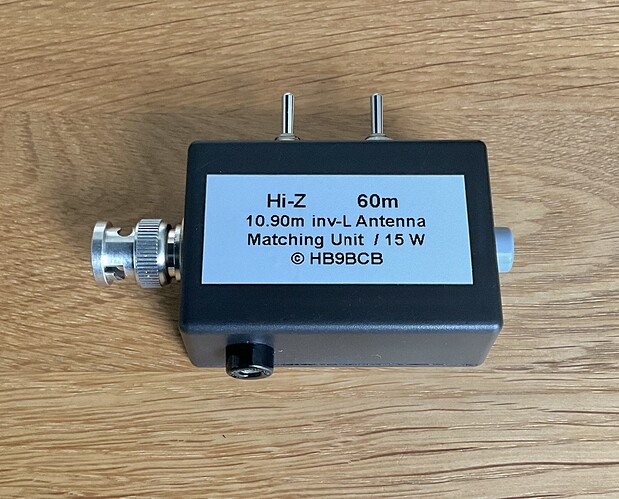
If you look around, the vast majority of people who build their own 9:1 transmission line transformers meticulously wind 9 trifilar turns on a toroidal core because they believe that this is the decisive factor for the impedance transformation ratio of 9:1 - which is not true.

The transformation ratio of a trifilar wound autotransformer is always 9:1, regardless of the number of turns.

For the operating range above approx. 10 MHz, for example, fewer turns result in fewer losses/lower VSWR (e.g. 7 turns #22 ECW on FT-82-43 toroid on my 10.90 m inv-L, needed at 14 MHz and only as a backup on the remaining bands).


2 Likes

I can’t understand that either. It’s been hosing down here for weeks. Driving down Deeside from Braemar last night and the Dee was very low and quite narrow.

Prrobably not, but it is a superbly compact and flexible (multi-band) antenna when used with a KX2.

Well I’m glad you’re finished with it. Get with the 21st century and hack up a Tesco* Value chopping board for your next antenna winder. You can even drill some “lightening” holes in it and fake a 3D printed one.

*other supermarkets are available

5 Likes

It’s so long (44 years) since I did magnetics (inductors, cores and motors) most of the knowledge has evaporated out of my head! Lots of time in lectures and lots of course work that was never used in my assorted jobs and (to quote Roy Batty) ‘lost in time like tears in the rain…’ :wink:

Time to dig about in boxes under the stairs for old University books for a refresher course Heinz.

Yes I think that’s the best way to describe this. One of antennas always worth carrying with you just in case.

I’ll shall invest in some chopping board on my return from foreign parts.

3 Likes

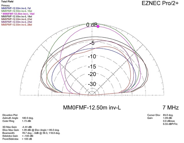
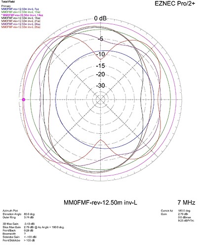
From the EZNEC plots for the original MM0FMF-12.50 m inv-L below, it can be seen that the mast height, radiator and radial lengths chosen for the multiband antenna result in only modest radiation characteristics, especially on the 17 to 10 m bands.

The main reason for the very pronounced steep radiation on the higher bands is the “radial” length of 5.18 m, which is far too long relative to the radiator length and, very unfavorably, one half-wave length long at 10 m.

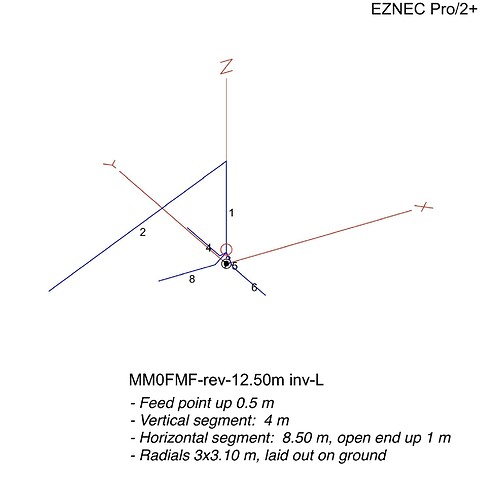
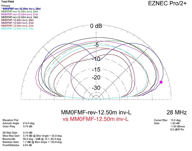
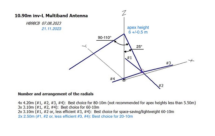
A significant improvement in the order of ~11/8/3/2.8 dB @ 28/24/21/18 MHz @ 15 deg elevation could easily be achieved with the radial arrangement shown below. With this geometry, the MM0FMF-rev-12.50 m inv-L would have some similarity to my 10.90 m multiband inv-L, which was originally developed for the needs of Bruno, HB9CBR, and which is therefore connected directly to the transceiver.

2 Likes

Thanks for these plots Heinz. I was playing with MMANA earlier today with the antenna as described and got the same plots as you. Not a DX antenna :slight_smile: However, if all that is needed is a simple change to the counterpoise then I will cut the wires and fit connectors in between packing my bags for the rally tonight and tomorrow. It can have a real world test somewhere in France later this week. Many thanks Heinz.

3 Likes

3x 3.1m wires prepared and added to antenna winder ready for testing tomorrow.

2 Likes

All we can do now is hope that the radial ends are insulated (-> maintain max. voltage/min. current at the ends) and that solar activity will be kind to you on your trip to the mainland, Andy

3 Likes

Heinz, the antenna works on 28MHz… I worked ZS6 despite k index =5.

3 Likes