In the QST issue June 2026, pp. 33-34, Phil Salas, AD5X, describes in “A Simple Transceiver Protector and SWR Tuning Indicator” how the accuracy of the well-known resistive SWR tuning indicator with LED display can be improved.
Phil’s brilliant idea:
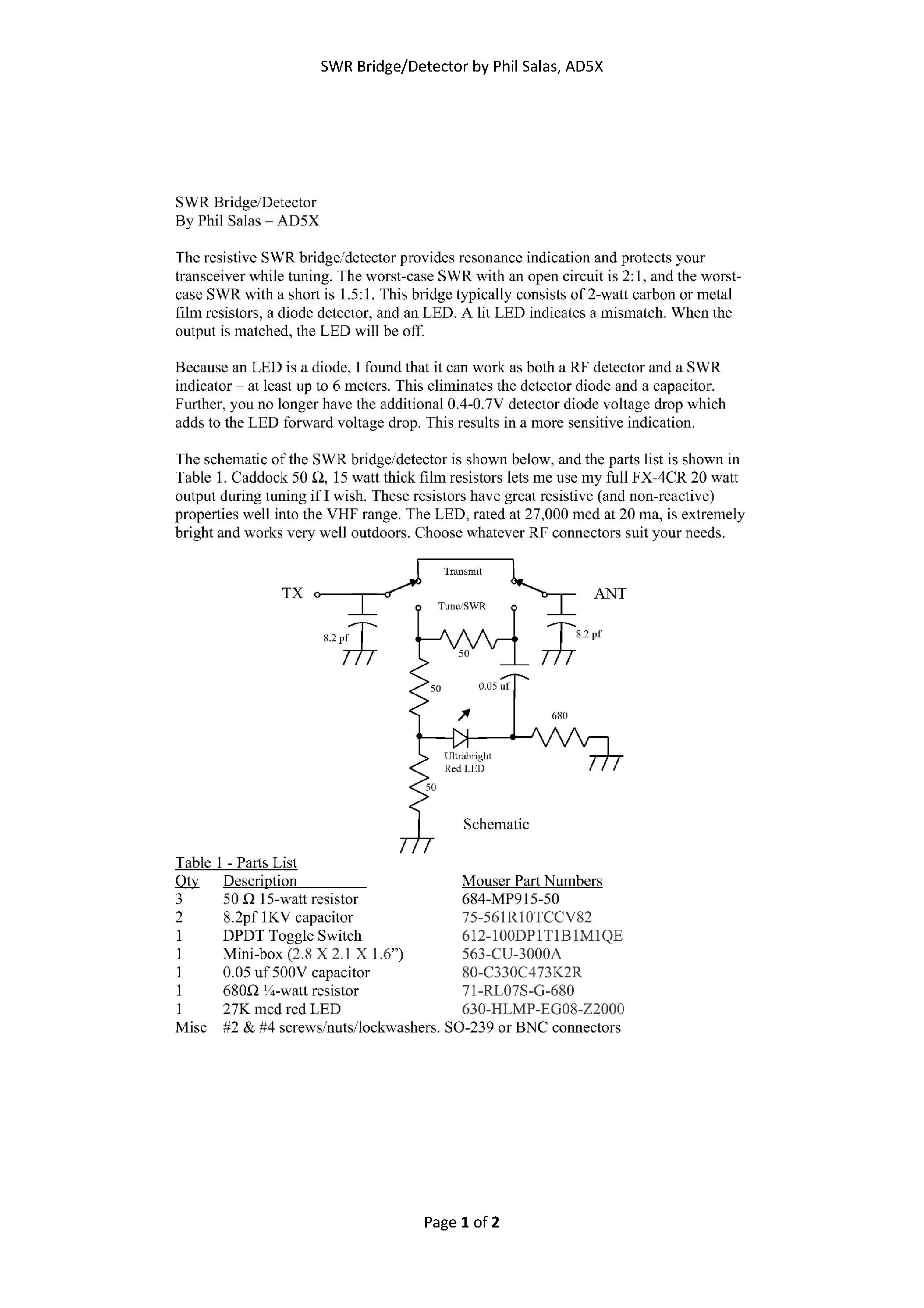
Improvement of measurement sensitivity by eliminating the 0.7 V voltage drop of the RF rectifier diode and having this function taken over by the LED instead
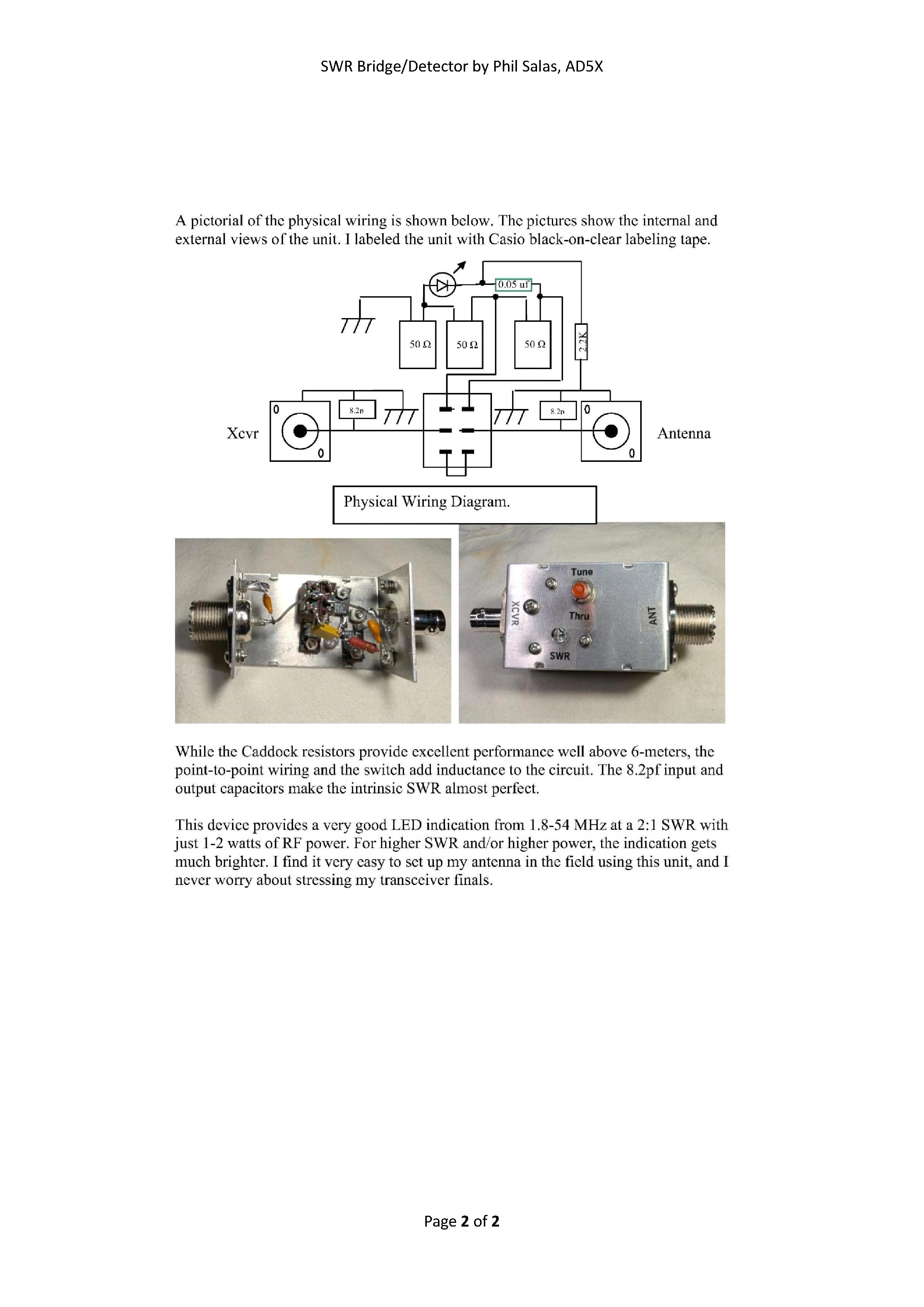
Improvement of display accuracy in the 1.8-54 MHz range by compensating for unwanted inductance through wiring using capacitors switched across input and output.
BTW, Phil built his SWR Tuning Indicator for use with his FX-4CR, even with 20 watts, so he used 15 W thick-film resistors in the measuring bridge.
I’m wondering if anyone has already modified their existing resistive SWR tuning indicator based on AD5X’s idea?
I think there is an error in the circuit, the 8.2 pF capacitors remain connected when switched from TUNE to THRU. They should be connected to the SWR bridge side of the switch.
73,
Luc ON7DQ
As Phil writes, it is to compensate for the wiring inductance, which has most influence on 6m.
I suppose this is is only for the wiring of the SWR bridge. There should never be that much inductance introduced by a simple through connection from one connector to the other.
As the circuit is drawn now, you’re connecting 16.4 pF in parallel to the antenna on every band … I don’t like it. Just my 2 cts.
73, Luc ON7DQ
However, upon closer inspection of the photo showing the interior, it becomes clear that the connecting wires to the switch are not particularly short.
Here is Phil, AD5X’s, response to this issue:
The internal wiring to the switch, whether in TUNE or THRU, adds inductance. The capacitors compensate for this. The extra wiring to the thick-film resistors adds very little inductance, and the resistors are actually very slightly capacitive. So it all works out nicely. If you look at the uncompensated figure, it only rises to about a 1.3:1 SWR at 50 MHz. But I’m kind of a perfectionist, and I wanted it to be perfect!!
73,
Phil - AD5X
Therefore, I believe that with a more compact design and very short connections, smaller capacitor values could potentially be used, or they could even be omitted entirely. However, the inductive contribution of the switch remains and is present in both operating modes.
To verify your own implementation, a reflection measurement (SWR/return loss) is recommended in any case, as documented in the original article by Phil, AD5X, in QST.