As propagation here is getting worse on the higher HF bands, I would like to try some 80m activations.
I already have the 80m version of the SOTAbeams linked dipole but it needs so much space to fit it in even using my 10m portable mast that I am looking for a solution that needs less space.
I intended trying 80m from DL/AL-167 Falkenstein on Monday (report on dd5lp/vk2ji.com) but I hit the problem of lack of space and this is quite a busy summit with walkers and tourists.
I have tried a tripod mounted loaded vertical from a summit before and have not had good results and the RHM-8B doesn’t cover 80m in any case.
I am probably going to buy the UL-807 from Aerial-51 if available at Friedrichshafen, however it also will need a lot of space to put-up.
So does anyone have a suggestion for a lightweight, horizontal wire antenna that doesn’t take more space than a 40m dipole while not being compromised too much? I know this is a lot to ask, but perhaps someone on this list has already solved this problem.
I suppose a magnetic loop antenna might be an option but I suspect one for 80m might be quite large to carry and do these antennas cover multiple bands?
Thanks for all suggestions,
Ed.
P.S. also needs to be not too expensive - self make preferred.
I am about to try out my FAMPARC antenna on my next easy to get to SOTA summit activation. I was thinking of a tripod at about 3m to get it off the ground. Wont be as good as the dipole but an awfully lot easier to set up. I do have an 80m extension set for my linked dipole and have put it up on Rileys Mountain in Sydney on a Sunday morning, but as you indicate it does take a bit of room and would be very awkward on some summits.
I know that you cant buy a new FAMPARC antenna anynmore but the Terlin is available whch is similar. TERLIN
Be interested if you come across a good 80m SOTA set up. It would be good for evening activations for local contacts in VK which I did recently at Bonfire Hill, where there is plenty of room. Worked OK.
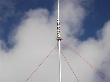
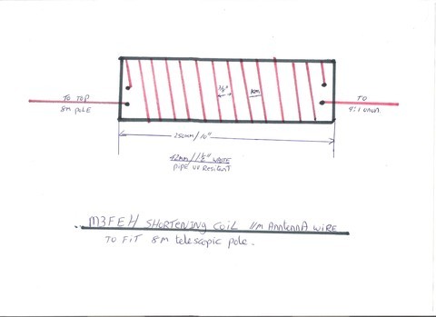
As you know i have a 40mb vert using 11m of wire on a 8m pole by using 25cm of 40mm waste pipe and popping in on top of the support cord and wind onto it loosely coiled 3m of the antenna with small bit coming off top and bottom enough to reach the 9:1 unun and the top of the mast as the pipe becomes part of the mast and storing of the wire from sota beams.
Am working on idea as in your case you have a 10m pole already so that,s 10m used up already of 22m wire required to make a 1/4w 80m vert. What i intend to do is increase the length of me 40m waste pipe from 25cm to 1m. Run wire up from Unun so high till about 3.5 to 4m high col up loose wire onto the pipe and rest left over go’s to tip. So on me pipe i will have at least 14 to 15m wire heli-coiled up the pipe spaced out about 1 cm apart to take up the slack. I call this my shorting coil. But its all contained on the squid pole.
My 1/4w 40m vert also tunes in on 80m but as a 1/8w but feel 1/4 would be better. Now me CP are set to 1/4w divided by 4 lengths. BUT have extensions to taken the to 1/4w length for 80m using banana plugs and jacks.
The shorting coil for the 40m 1/4 wave works well even on 10w but better with the CP set at 1/4w but four legs totaling combined to the said 1/4w length of the CP. So can’t see why not making me shorting coil that much bigger to take the extra wire to take up the 22m of wire
BUT don.t wind the coil wires next door to each other tightly spacing is required as i found do that and you will lose the lowest band your trying to run. Now by rights you should be able tune it down with good tuner as my MFJ handles it no problem.
But prior to winding up of the coil get a lid for the waste pipe drill hole big enough so slides down the squid pole till its at a happy place to sit fairly high and guy ropes sit above it happy or below it depending on how you set them in first place, then start on coiling of the shortening coil.
This is one experiment one is thinking to do before long before the MUF drops to much and should work.
As I see it, there are three simple solutions. None are ideal as you are talking about compromises, but all work and are not expensive.
Solution 1 is a multiband trapped dipole, the Sotabeam traps seem to be ideal for this, and as you know, each pair of traps shorten the overall length.
Solution 2 is to use a pair of loading coils, one part way up each arm of the dipole. A variation of this would be to add capacitance at the ends making an antenna like a stretched “H” but this leads to complex support problems.
Both solutions 1 and 2 increase the wind resistance of the antenna, so I favour:
Solution 3, a doublet antenna with a lightweight tuner fed with twin lead having an impedence of the order of 100 ohms. A doublet about 20 metres in overall length will still have a reasonable efficiency on 80 metres and a Z-match using two solid dielectric tuning capacitors and the coils wound on a good quality ferrite ring will be small and efficient - mine is built in a box 130 X 60 X 40mm and with a 20 metre doublet will tune all bands 80m - 10 m.
[quote=“G8ADD, post:5, topic:12888, full:true”]
Solution 3, a doublet antenna with a lightweight tuner fed with twin lead having an impedence of the order of 100 ohms. A doublet about 20 metres in overall length will still have a reasonable efficiency on 80 metres [/quote]
That is exactly my wisdom and experience.
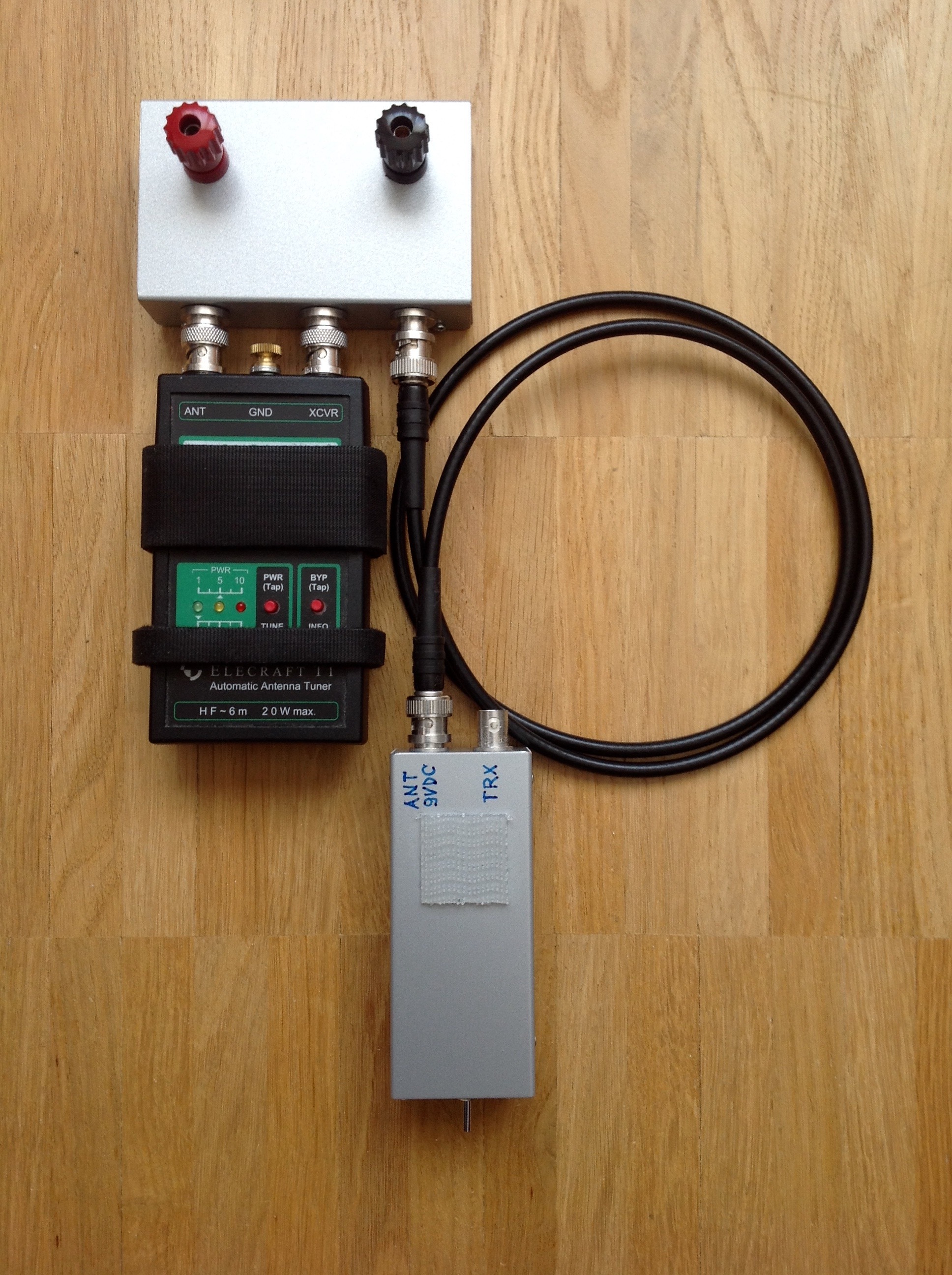
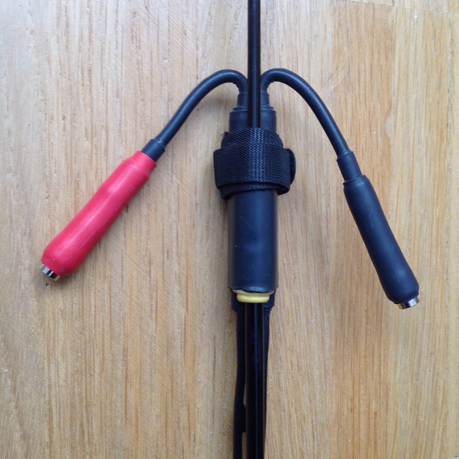
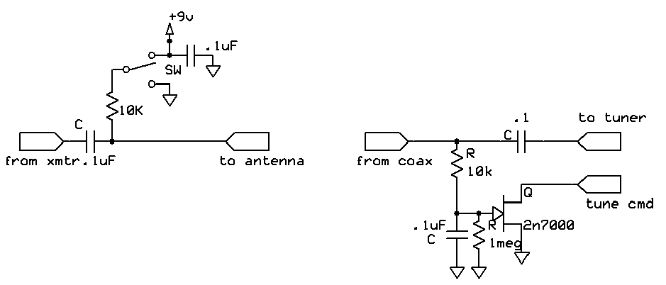
The fotos below show the base and top of my proven 80-10m multiband doublet (inv-V) with a remotely controlled T1. The remote bias tee is mounted inside the T1 (bias tee built according this: http://jtmiller.com/T1%20tuner%20control.BMP)
Coax between local bias tee/TRX and tuner of any length.
Ladder line length as practical, its electrical length (e.g. Vf 0.9) is added to the length of the antenna legs.
Hi Compton, thanks for the suggestion but the Terlin seems a little expensive at $250+ (especially with shipping on top) to buy without knowing that it will work for me. It would also be a custom build for amateur bands if I read correcty.
Actually looking at the ad, I realise I have a tapped mobile whip that I bought at Friedrichshafen a couple of years ago but I’m almost certain that only does 40m - 10m - but worth a check if I can find it HI.
Thanks for the suggestions Karl, as per our direct email, I think using some kind of inverted-L or T might be a solution. My tests with shortenning coils on my 80m dipole at home suggest to me that such a design loses too much performance and a different solution without coils might be best (and possibly lightest as well).
Heinz - that looks like a great idea - I was thinking of a T with 10m of vertical parallel cable and then simply 10m of cable at each side to make the 80m dipole. Which would then only be for 80m but by G7FEJK offseting the feed at the top this is now like an OCF but using the vertical feed as part of the run as well. I’m printing this design out now to take a better look at it thanks.
Brian, thanks for your suggestions as well. My biggest enemy is available space, so I’m afraid a trapped or linked dipole is still to large. Loading coils I have tried and am not happy with the performance of the antenna, here at home (I could have done something wrong of course). Option 3 however, the doublet could also be a winner. Like the Kantenna some of the length of the antenna is taken up in the vertical section, so reducing the needed length of the sloping sections.
Thanks to all for your quick responses, I’ll let you know what I end up with and how well it performs in the end.
I too like the idea of a shortened doublet fed by balanced feed into a tuner. I would use either 300-ohm windowed twin lead or 100-ohm twisted pair. I harvested lengths of twisted pair from salvaged CAT5e cable. It uses teflon-like insulation and makes for low loss feedline. I’ve used it successfully on a few activations with a 44 ft doublet (6.7m per side) for 40-10M
Well it is a little larger but I found that a double sized “Norcal Doublet” (88ft long) made out of computer ribbon cable was very effective on 80m (and very light) when used with 4:1 balun and tuner next to the operating position.
It was also (not surprisingly) very good on 60m and I even strapped the feeder and fed it against a long counterpoise for reasonable use on Top Band.
If i remember rightly when you did your coils they were like traps with wire wound closely together on where mine are spaced apart to avoid the inductance effect.
Now me 1/2w 40m inverted L might be of use to you built in same way as the with losing the 3m or wire in same way and then 11m comes off the top of the pole and down wards towards another support keeping end about 3m off the ground. And will tune to 80m as 1/4wave. As I know this one cracks out well as when last used at Rame head at reduced height cause of winds even on 40m worked parts of Europe and UK and Sweden. and on 20m was all over Europe and one station in states side. By doing the coiled part of the antenna and keeping it fully vertical means no wires dangling down like you said sometimes not the room to have that bit of extra wire coming down as an inverted L. Hence i have the 1/4w version of the 40m.
But some interesting ideas being thrown around and interesting to see the different ways peoples have. Do like me home brewing and making them work and improving on what you have and certainly replacing the one CP wire by chopping it into four but same length as the first one when adding the four together does make a difference as found out down Rame head in SX44. Man had some cracking signals coming even Sweden was banging in a good one on 40m.
But one day do want to try what i said and make a vertical 80mb 1/4w antenna portable of course and yet only need one pole just interchange the antennas depending on surroundings of the time.
I would also recommend a 88ft double fed by open wire line on a 10m pole. Anything shorter would require loading coils otherwise the efficiency will be very low.
I thought of that - as I use one myself for 80/60/40 metres SOTA - but he specified that it should take no more room than a 40 metres dipole. It could perhaps be shortened with a loading coil.
Perhaps I’m asking for the impossible (as usual), but these are my design criteria(in order of importance):
small ground space requirement for summits with restricted space.
lightweight
no heavy losses through loading coils if possible
resonant antenna.
multi-band coverage
Others may have other criteria.
I actually made what I think was my first SOTA Chaser contact on 80m yesterday with Stephan OE6SWG on OE/ST-287 - and I forgot to ask him what antenna he was using - DOH!
Loading coil losses are heavy if the loading coil is at the feedpoint. Moving the loading coils to part way along the arms of a dipole reduces the losses considerably. The same thing applies to a vertical, moving the loading coil from the base to some way up the vertical reduces the losses. Note that you can also add loading coils to the radials.
Hi Heinz,
Unfortunately I have to remove the G7FEK antenna from my list of possibilities as the horizontal sections have to be close to horizontal (i.e. not Inverted-V format). This means at least both ends of the antenna need a support (and ideally the middle as well). Possible antenna for home use but not on a summit.
"In the Technical Correspondence section of the September 2006 issue of QST (page 57), are a few paragraphs written by Dr. Jack Belrose, VE2CV. Jack explains how to use an antenna analyzer and EZNEC to calculate the efficiency of a mobile antenna. The basic premise is to compare the measured input impedance of your mobile antenna, compare it to the modeled impedance given by EZNEC, and then adjusting the coil Q (resistive loss) until the two impedances (measured and calculated) equal. Then reading the programs calculated radiation efficiency. "
[taken from Antenna Efficiency]
I would do that and see if your measured and simulated impedances match. If not you need to tweak the coils. How to do this is left as an exercise for the reader.
