Thanks for the mention Pascal. Taking a break from building Summit Prowlers at the moment, and watching this and a few other similar projects with interest. The decisions and trade-offs in designing, bulding and using pocket QRP rigs is one of the most interesting things in amateur radio, for me at least. And SOTA makes all the hours and effort worthwhile. 73 Paul VK3HN.
5 Likes
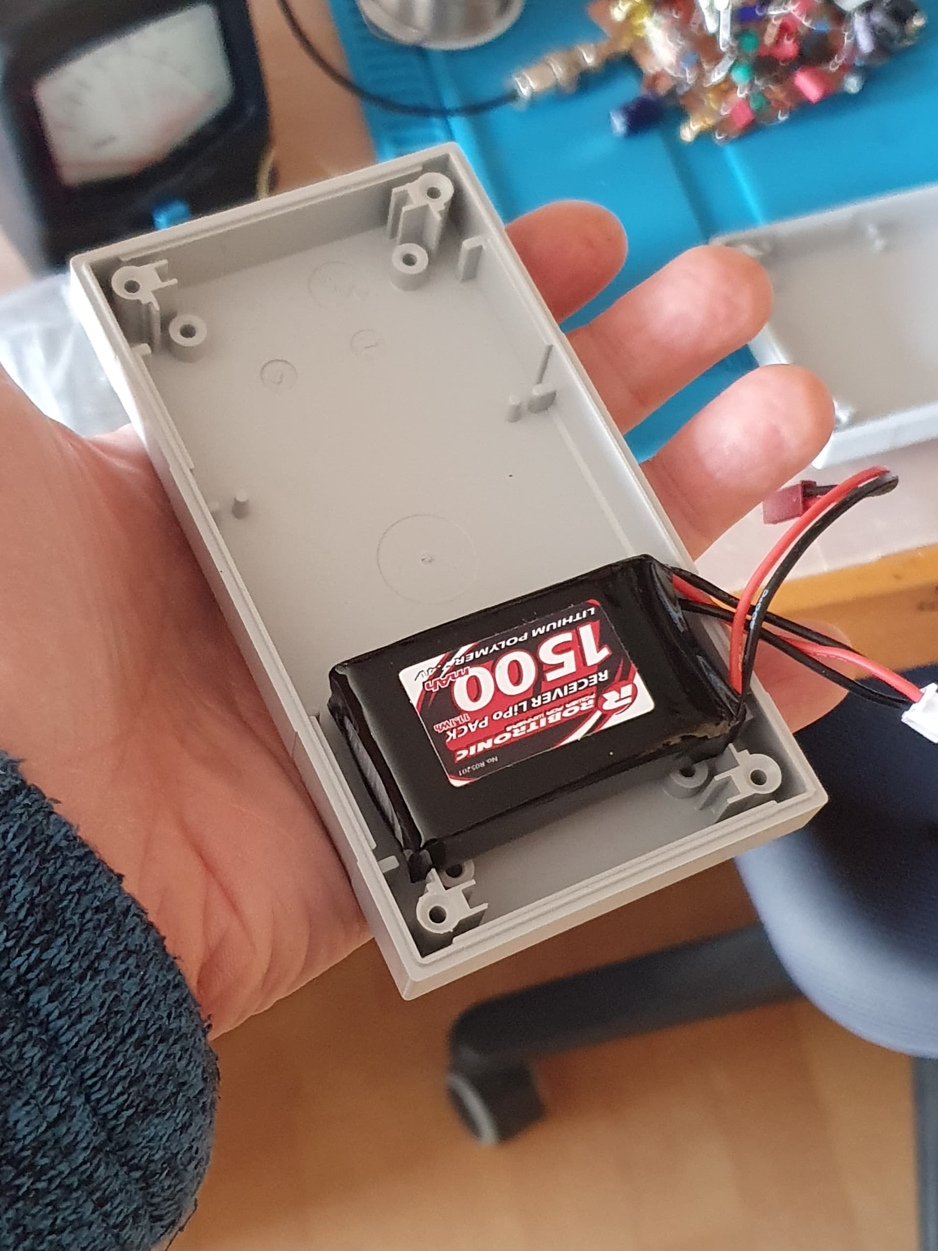
The postman brought me the planned 1500mA/7.4V Lipo today, a cute thing. This made me want to build the Spota One in a small case measuring 3x6.8x12.5cm.
I’m excited to see whether I’ll succeed.
73 Chris
5 Likes
Your Spota One will fit nicely in one of our yoghurt pouch with room for accessories (external dimensions 20x9x4 cm)
https://www.coolpod.com.au/yoghurt-pouches/
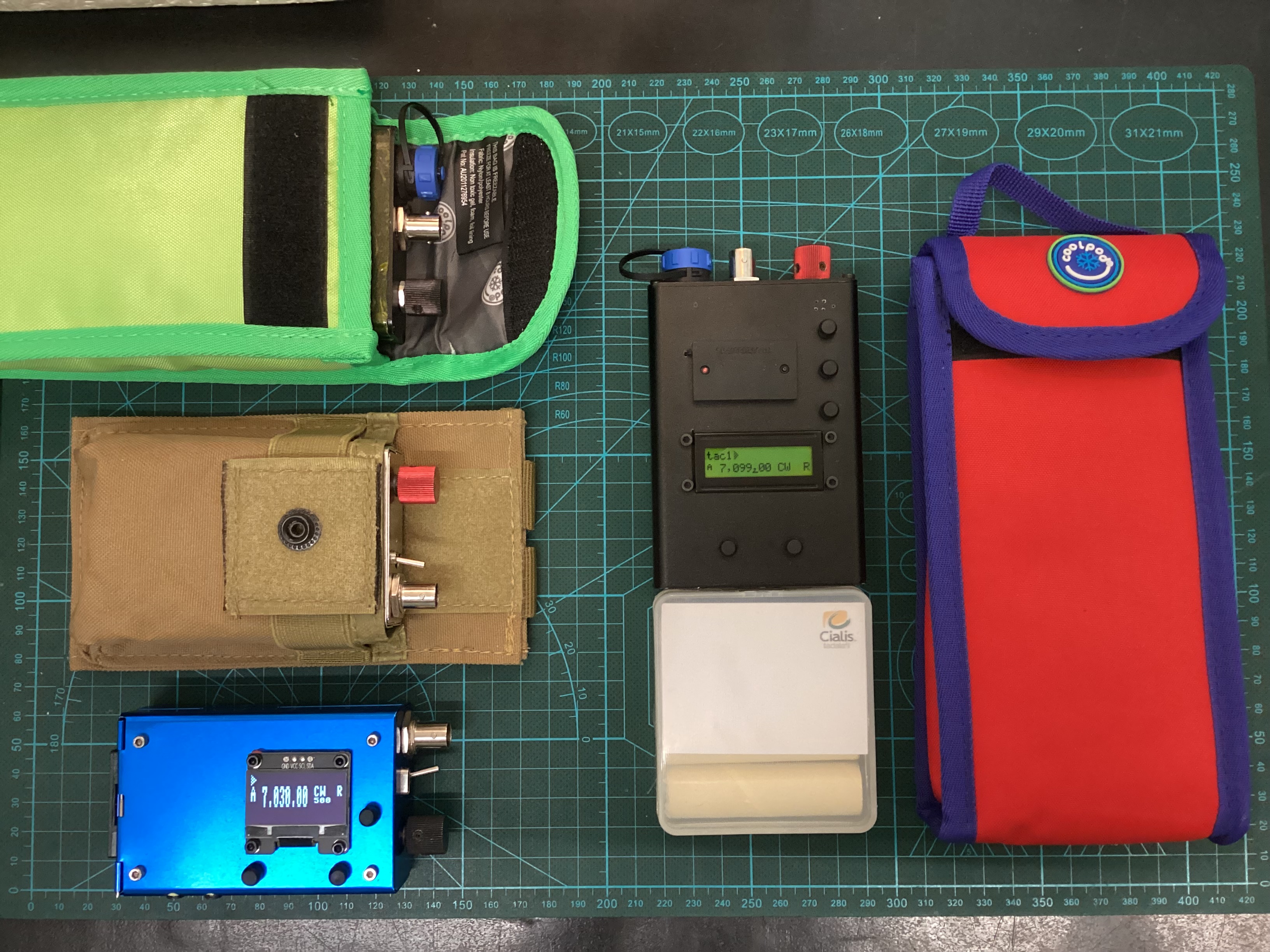
For smaller rig, I use UV handheld pouch from AliExpress (11x6x3 cm)
@VK3HN, your Prowlers niche has an empty slot for up-conversion rig, would be very interesting to see you brewing one, hihi.
73 Pascal
5 Likes
You’re right there, a uBitx type of thing… also I have not done much with baseband IQ demodulation.
Your little CW rigs in tour pictures look good, what are they?
3 Likes
It is a uSDX tribander with 2S x 18750, built inside a Chinese cigarette box 9 x 5.6 x 2.8 cm. I am happy with the transmitter with class E “Shunt Capacitance topology” (original uSDX was designed with “Serial Resonance class E”https://www.rfcafe.com/references/articles/Load-Network-Design-Techniques-for-Class-E-RF-and-Microwave-Amplifier.pdf
The receiver is a bit of stone deaf (-100dBm MDS).
73 Pascal
3 Likes
The black one is a tactical uSDX, for bush walking, was built for CB 27 MHz and 6M band suitable for short antenna with 4S 18650 batteries. The display is a reflective LCD 16 x 2.
3 Likes
Using the Fuchs Antenna matching unit for the EFHW gave me the idea of coupling the resonant circuit directly to the PA transistor. The tests were very successful, the efficiency with the target output impedance of 3k Ohm is approx. 66%. That means 5W out at 8V/0.95A DC input.
The simplifications should make it possible to install the Spota One in the small housing.
73 Chris

3 Likes
Interesting manoeuvre to substitute LPF with Fuchs tuner.
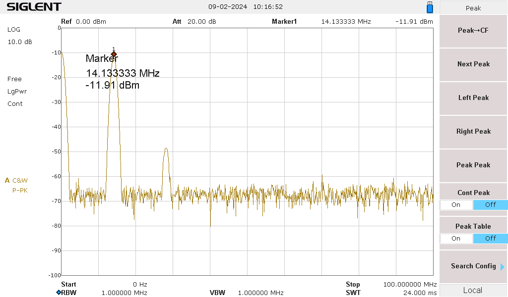
How do you measure the 3rd harmonic?
73, Pascal
4 Likes
Hi Chris,
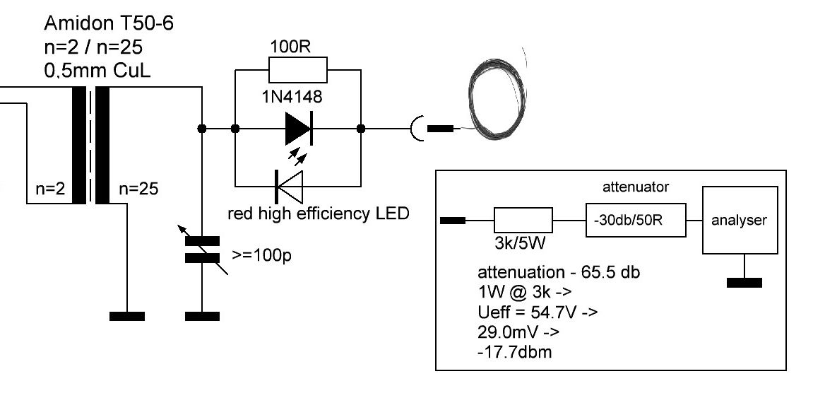
just a suggestion : you can eliminate that 100 Ohm resistor + diode + LED, and use this instead. Just slip it over the antenne wire, and once tuned you can remove it if you wish.

It’s not my idea, I found it somewhere on the net.
I used 4 windings through the ferrite core, and just connected a high brightness LED. Tune for max brightness. Done.
Luc ON7DQ
3 Likes
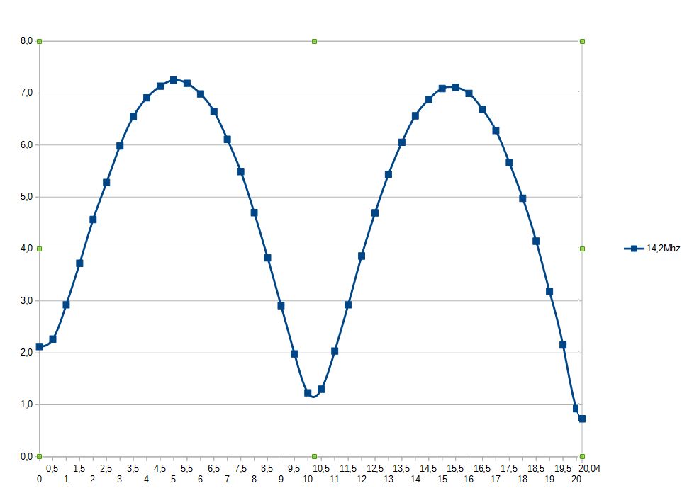
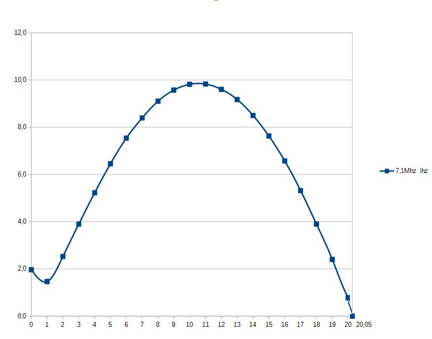
During my first attempts with the EFHW 10 years ago, I measured the current in the antenna wire over its length in this way. And instead of the LED, a small LED measuring module is used. Here are the results.
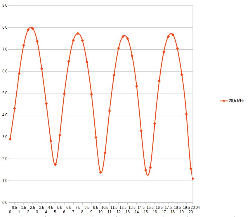
3 Likes
In the last 40m diagram you can see, that the wire should be a bit shorter for 40m band.
1 Like
Peter, HB9EBE asked me:
Try to understand as much as possible, your toroid has a gear ratio of almost 8000 ohms. For me, EFHW close to the ground works better at 2500
My answer:
This is because the output transistor has a significantly lower impedance than 50 ohms. That’s why HF transformers can always be found in all power amplifiers. The output impedance of the power amplifier can be roughly estimated using the ohmic equation R=2U/I, here 2*8V/0.8A = 20Ohm.
The 0.8A refers to the current through the output transistor without driver current.
With a gear ratio of 2:25 this results in 3.125kOhm.
Thanks for asking, I only just became aware of everything now. Learned something again!
73 Chris
1 Like
Hi Chris,
Without any background in EE, I have to rely on “on line calculator”to learn how to calculate insertion loss of impedance matching from 3k to 50Ω with a 3k resistor in series and a 30dB attenuator from your sketch.
I found 23.57dB of insertion loss from Online Calculator .:. Minimum Loss Resistor Matching Network
I replaced your -65.5 dB with the L pad value:
attenuation -53.57 dB
1W @ 3k —>
Ueff = 54.7V —>
109.54mV —>
-6.198dBm
With this setting of LPad, it seems to me that I can achieve a lesser loss than your matching resistor in series, perhaps I might see a third harmonics that was buried in noise from your snap shot? (I own only a homemade SA with 50dB noise floor).
Love to learn from you, about matching with a resistor in series.
1 Like
The attenuation calculated on the website may not be correct. A voltage divider R1 = 50 Ohm and R2 = 3000 Ohm (exactly 2950 Ohm) results in an attenuation of 1:60 and that is - 35.6 db.
73 Chris
1 Like
I used that website calculator for L pad loss which is based on power ratio (-22dB).
Yours is a voltage ratio 1:60 (-35dB)
I am confusing, great that you are kindly helping me out of the black hole of EE mathematics.
73, Pascal
1 Like
Hi Chris, tried your EFHW idea on the ground in dry southern Italy, with Fuchs tuner. Against EFHW L-config 6m high with 1:49 balun about 10 db less on rbn. But no problem to chase a peak in Germany and another contact with 5w on both sides in the UK. Brilliant easy and fast solution. Thanks for the idea!
73, Peter
2 Likes
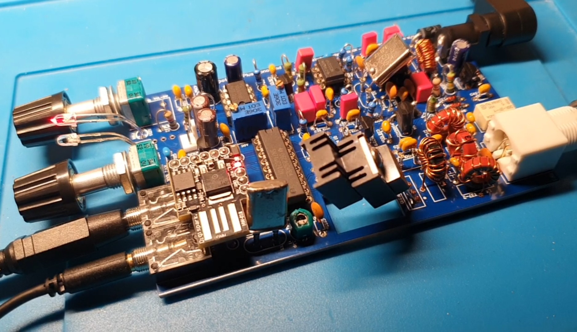
I am pleased with your positive feedback. And motivates me to finally put my Spota One in a housing.
Maybe the antenna - as small as it is - will also be a good addition to the QMX for 7-9V that I recently ordered. I couldn’t help it, but the concept of supplying 8V from just two LiPos is another step towards activation without a lot of weight and effort.
73 Chris
2 Likes
Hello Chris,
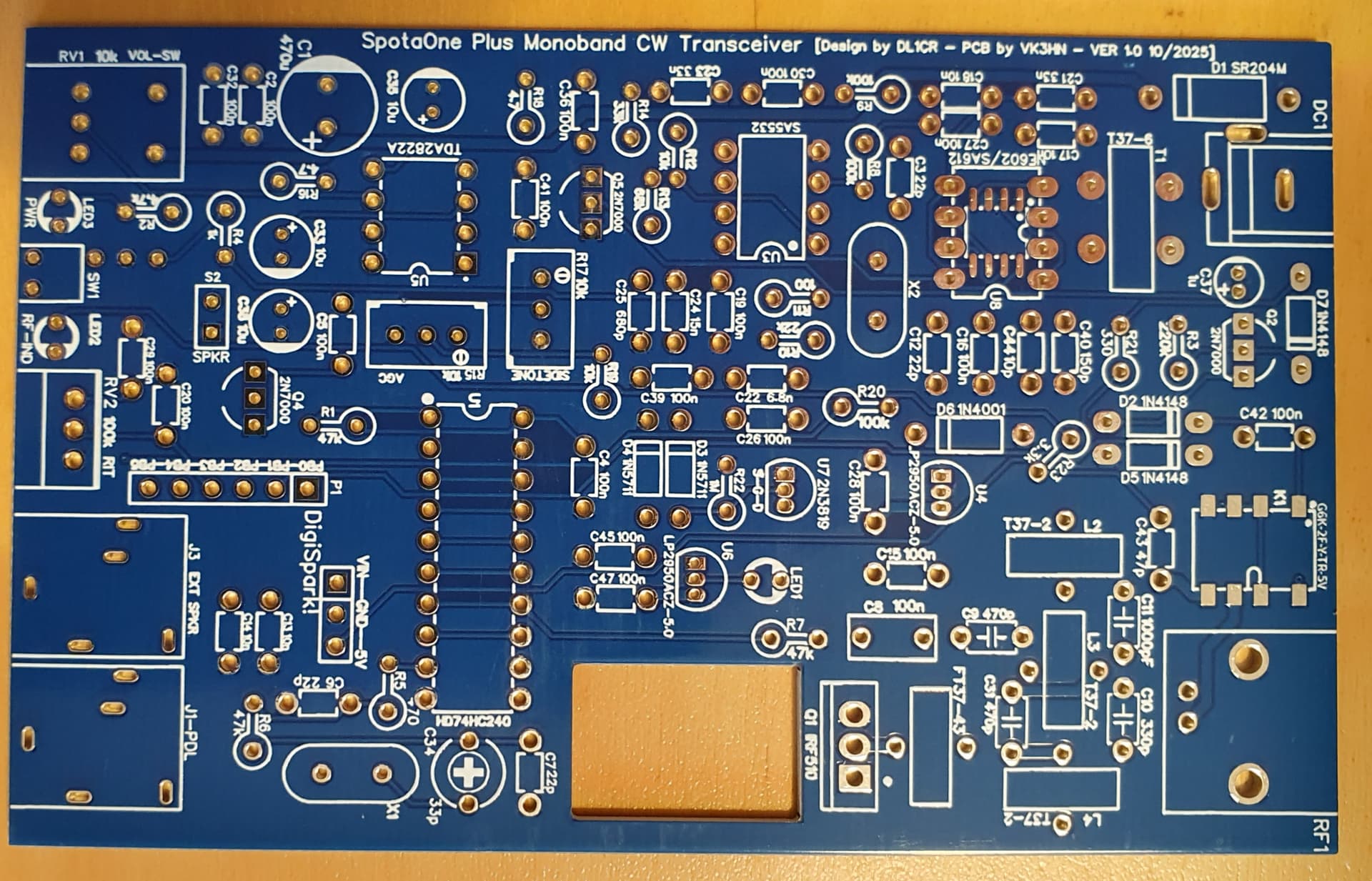
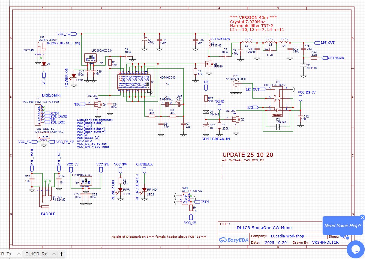
This little SpotaOne keeps intriguing me. The crystal locked Tx using a single octal bus driver for oscillator, driver and to pull in the T/R relay is so clever!
When I look at the circuit I wonder about the T/R switching. As all of the gates are enabled at the same time it seems that the drive and full IRF510 RF power must be applied to an open circuit for the brief period while the relay contacts switch. This is not ideal for various reasons but I assume it didn’t cause any IRF510 problems on a 7 volt Vcc (I have blown these FETs up on summits due to poor SWR so I regard them as potentially unreliable). Does the T/R change over sound OK?
And when sending, the Rx is powered up, with input shorted, so with its 700Hz offset it provides sidetone.
The relay must see about 7 volts, is it a 5v relay or is it rated higher?
I also wonder if you got your four band design going. The one with microcontroller, si5351 breakout, and another clever scheme using a different bus driver IC to drive a pair of IRF510s in push pull. How much power did this deliver?
Thanks in anticipation Chris. Your minimal QRP designs keep me entertained when I can’t sleep at night.
5 Likes