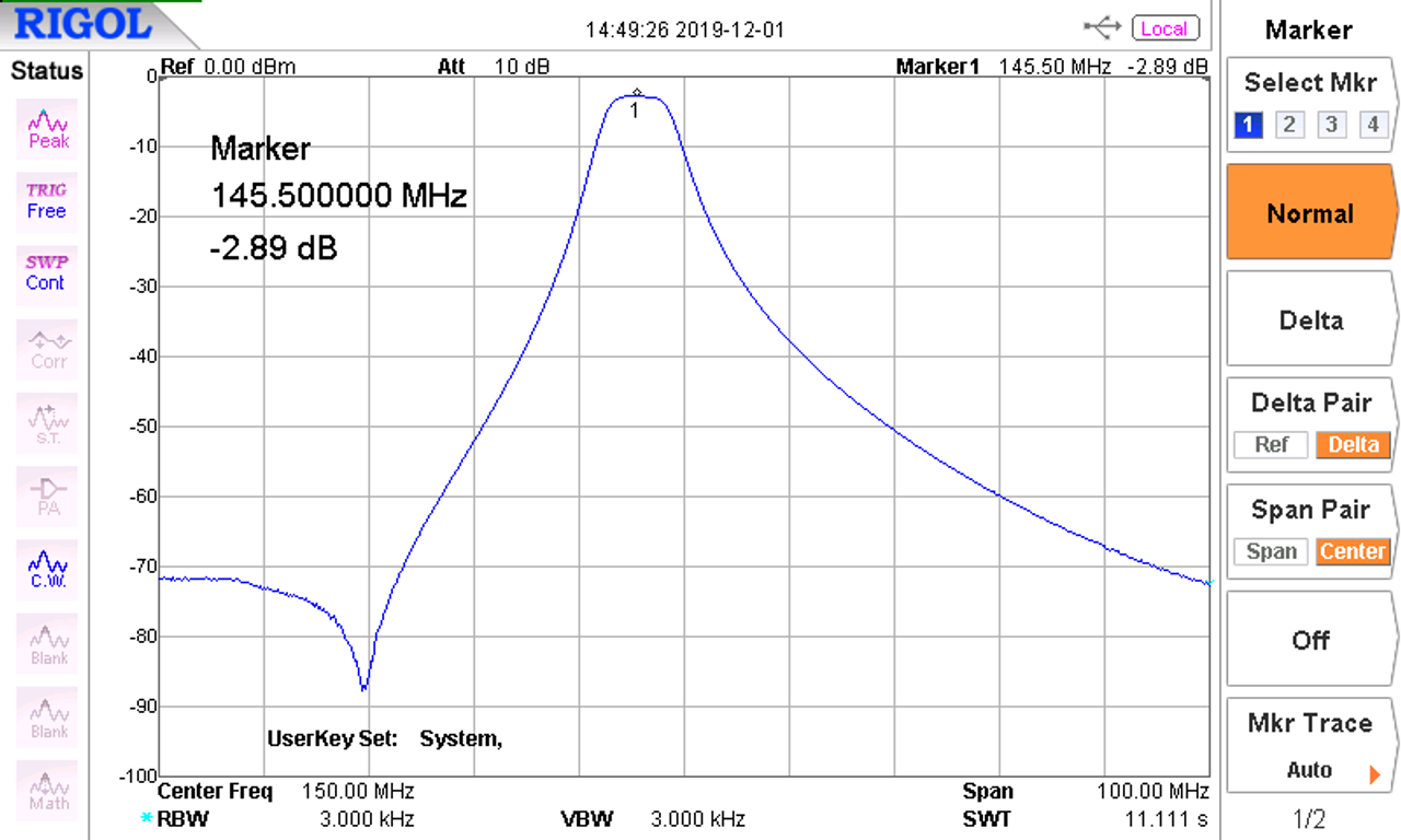
My SOTABeams filter seems to have gone deaf. Anybow we tried it on the VNA in club tonight, the curve was as expected, and in the words of my pal “its a very good filter” however the loss was around 5db and this seemed somewhat excessive?
Can anyone tell me the figures so we can see if were in the right ballpark, or if this is indicative of a fault?? Also any other test figures could be handy, I really dont wanna bin it and buy another, as im somewhat skint! But its also an invaluable piece of my opearting kit!
Am I right that the filter per spec attenuation is around 3 db? If so 5db doesn’t look deaf, but rather a bit out of spec and could be normal (perhaps within its tolerance)? That is, providing VNA tester was calibrated and showed correct attenuation values.
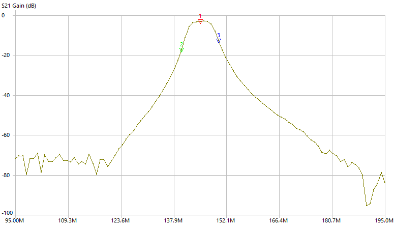
Hi Alan, that is a formal SOTABeams graph from here https://www.sotabeams.co.uk/bandpass-filter-for-2m/
I wouldn’t worry too much anyway, fairly unlikely you notice a real difference in a field, unless you’re keen for some 2m DXing? On a good side, if a bandpass is having 2 db of extra loss, perhaps the unwanted portion also has some extra 2db attenuation?
Is it getting hot when you transmit through it, Alan?
5.2dB loss means that only 30% of the power is transmitted: the remaining 70% being abosrbed (and converted into heat). So from every 5W from your radio, 3.5W is heating up the filter.
No, it has got hot in the past, but that was “duty cycle”… Ie me getting carried away with long QSOs! hahaha
Im wondering if its the same, as i snapped a pin off a male, putting them together! I cant see the remnants of the pin, but im wondering if it stuck in there… i might have to replace the SMAs
Is there an SMA missing a pin, easier to find maybe?
I’m going to lick my finger, stick it in the air and say… too much power too long and a component is “degraded”. That could be it’s value has changed a lot since it was cooked, or it’s O/C, or a track is O/C.
Mine were loose - you could pull the SMA connector straight off the chassis.
They were a pig to unsolder (multiple pins, tiny solder joints and the brass chassis acts as a huge heatsink). If you do decide to replace the connectors, make sure you get the long ones so you have enough length left sticking out through the case.
I swapped one of my connectors for an SMA male (to save a male-male coupler on my HTs) but it’s really fiddly to use so wouldn’t recommend it.
yes, you can see it clearly snapped off, i was rushing when i was fitting the converter to the filter, and didnt have it perfectly square
Not convinced TBH, it worked fine when i last used it, and the degradation in signal ETC happened after i snapped a SMA pin, so im thinking its SMA damage, we’ll see… I have replacements!
Pal of mine is going to do it, i dont trust my soldering, im a bit ham fisted for fine work! he spends all day with a soldering iron in his hand, so will take him a few mins and job done! and we have to connecters already, he had some in stock so were good to go!
Soldered new SMA’s on, and its now down to about 3.2db so a decent improvement! we had a look at the ends of the removed SMAs in the electronics microscope, and the ends where the pin goes in were VERY worn and splayed, and one looked badly deformed aswell… reckon this was the source of the trouble! Havent had an on air test yet, ill be doinfg that later on, or tomorrow… but its looking VERY promising!
We replaced the SMAs using proper old fashioned leaded solder as its melting point is lower, and its easier to remove for when we next change them! further updates to follow with the on air test
SMA have a life of about 500 connections. That’s the good ones not the cheap tat from China. So invest in some of the above and then you will be wearing out those which are easily replaced.
Many people do not know that you should not rotate the male pin in the hole, you offer the male to the socket and turn the outer. That way the pin stays still. If you rotate the whole connector, like fitting a rubber duck then the pin rotates and can wear the plating from the mating surfaces. Or worse chew up the surfaces so they no longer mate.
So buy some protectors and destroy them. I have some on my 13cm transverter for this purpose. The cheap noname Chinese ones are normally OK to 23cm but beyond there you may find odd resonances that spoil things. Check them on the VNA. Mine seem OK.
A nice man gave me some lovely Radiall latching SMA relays for the rebuild of a 23cm transverter. They are 30years old from a scrap item. They are stupidly expensive new. They’re good to around 1.5GHz he said but awful on 13cm and 9cm and then OK on 6cm. So even full price top tier manufacturer’s items can have issues. But 2m, which is DC to be honest for SMA connectors you’ll be fine.
I intend on doing next pay day… that is a bloody good idea!! thanks Andy
im VERY guilty of that… without a doubt!! im also a bit ham fisted sometimes and have snapped several pins off the male ends carelessly connecting them… so these would save on ham fisted damage!
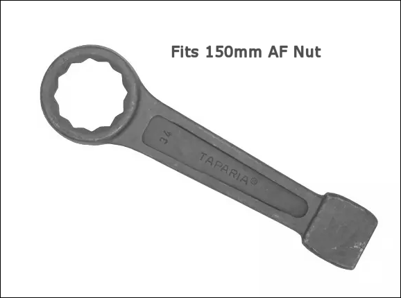
Those who have worked in heavy industries will likely be familiar with the so-called ‘flogging’ or ‘slogging’ spanner. The image below shows one sized to fit a 150mm (~6in) AF nut.
The user hits the end of the bar repeatedly with a sledge hammer to ensure the nut does not work loose is service, and any associated joint remains tight
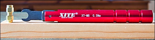
By contrast, for precision RF work using SMA connectors, a suitable torque (pronounced ‘talk’) wrench is used to fasten the nut to about 0.5Nm for the brass type: