Maybe there should be a SOTA Chase report category on the Reflector to mirror the SOTA Activation category? - there is, my fault, please disregard
Some of you may remember this discussion a while back about line of sight from near my home QTH when attempting to chase activations of GW/NW-001 Snowdon.
Today I had a chance to test the theory when Phil from Ludlow as GW4HQB/P activated Snowdon at lunchtime.
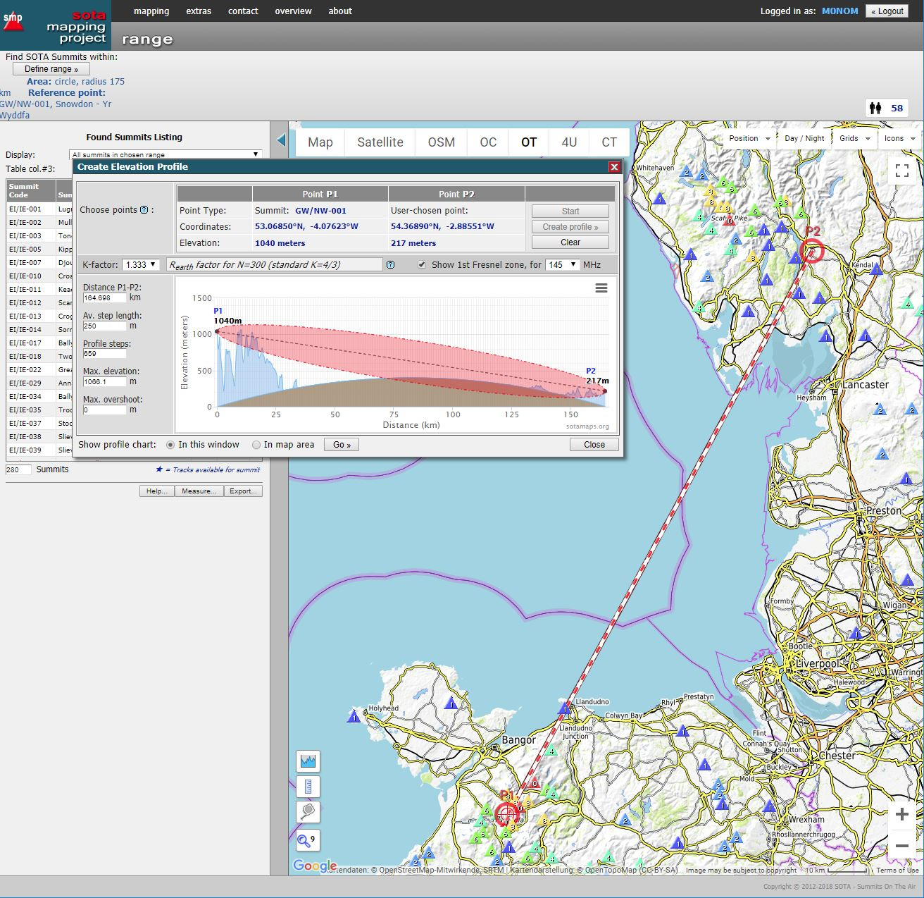
Rob @DM1CM kindly added me to the test team for the new mapping incarnation so I was able to make good use of his line-of-sight tool today to check a couple of possible locations for a chase - two local Wainwrights within 20 mins walk, Brant Fell and School Knott. As it happens we were walking the neighbours dogs which mean School Knott was an easier proposition for my wife to keep the dogs occupied.
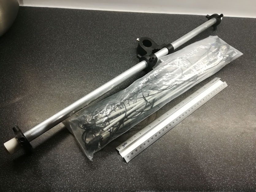
The signal strength was helped by both ends - I was using my Sandpiper 2m delta quad and Phil was using a German made log periodic covering 2m to 70cm.
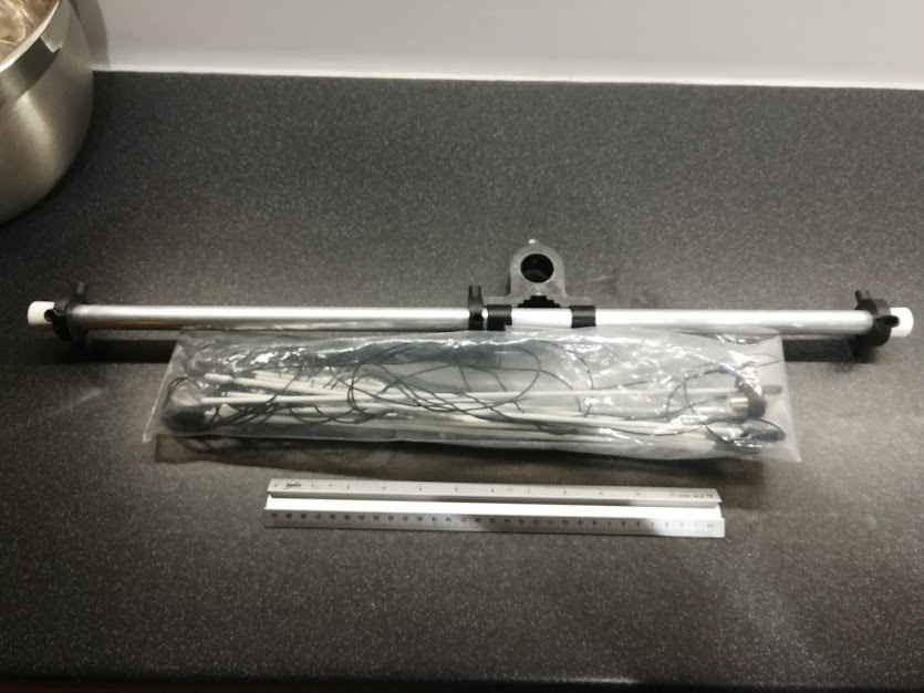
Boom length: 68cm, element lengths: 44 cm, weight: 425g
It is a great size, much better than trying to haul a 2m yagi to a summit!
I think on a good day you’ll get it going in around 5-10 minutes - good storage technique is key. Probably judicious use of rubber bands to separate the wire parts of each of the reflector, director and driven elements would make a big difference to stop them getting tangled, or separate plastic bags. Today went really well and it took about 5 mins.
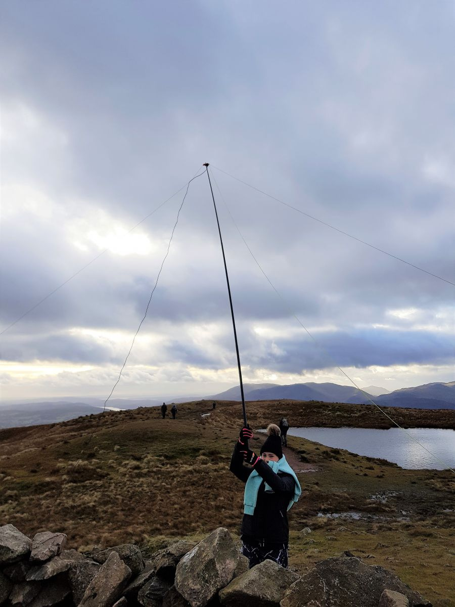
In a stroke of uncharacteristic good luck the clamp on the boom press fits perfectly on the top of a 8m fishing pole section - this particular pole bought it on a Red Screes during a transatlantic S2S party which resulted in my daughter holding the remaining section and we still got George @N1GB in the log with some daughter-made QSB!
I’m sure Mark will want to add his own comments here, too. As you say, there’s an awful lot in the way between your QTH and Place Fell.
According to what I’ve read about Fresnel zones, the QSO should not have been able to take place - that’s the “theory”. In practice, however - and following up on what Andy @GM4LLD and others have said in the link quoted by Mark in his first post above - other factors like tropo ducting (have I got that right?) come into play and make possible a communication link that “theory” says is not possible.
Having said that, the QSO is pretty remarkable over that distance and those big lumps in the way! BTW, do I see some kind of cobweb antenna at your QTH?
Most likely is tropposcatter. This is where both stations can see a common volume of sky a few km above ground and radio waves are reflected from dust/water in that volume. If sufficient RF is reflected back down to earth then you can get longer range VHF and up contacts. It’s the normal non-line of sight VHF propagation method. I’d suspect some diffraction over that peak to left of P2 may have helped.
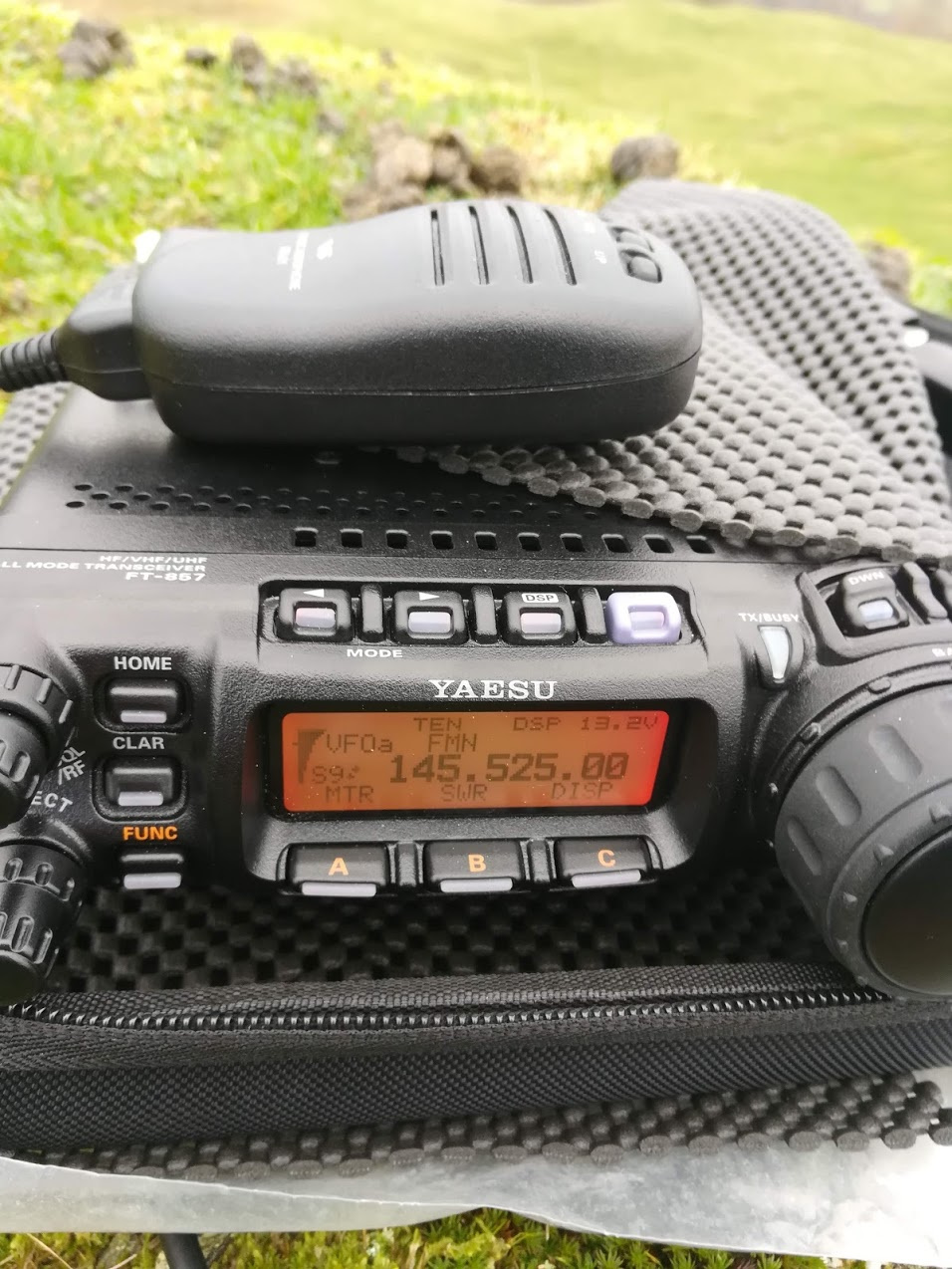
Most importantly as FM has a poor “watts per Hz” figure compared with SSB or CW, running 50W at the activator end gives a huge benefit.
There could be other factors that helped, but I’m with Phil in thinking it’s not a path you’d expect to be viable. It could be if you tried the same thing every day for a month you may find it only works, say, 40% of the time.
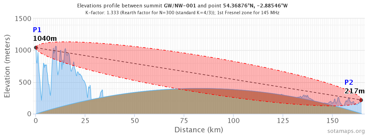
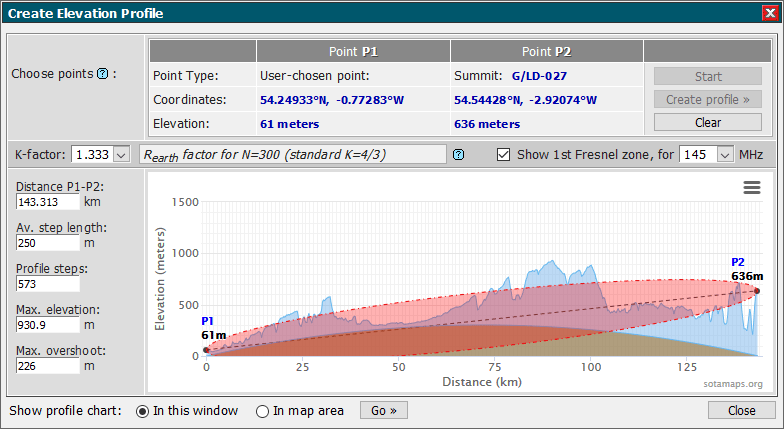
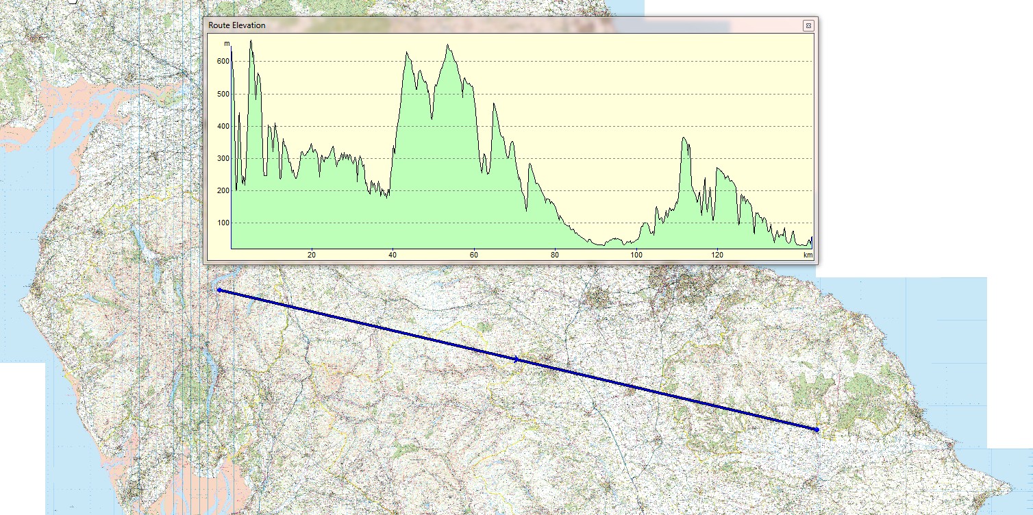
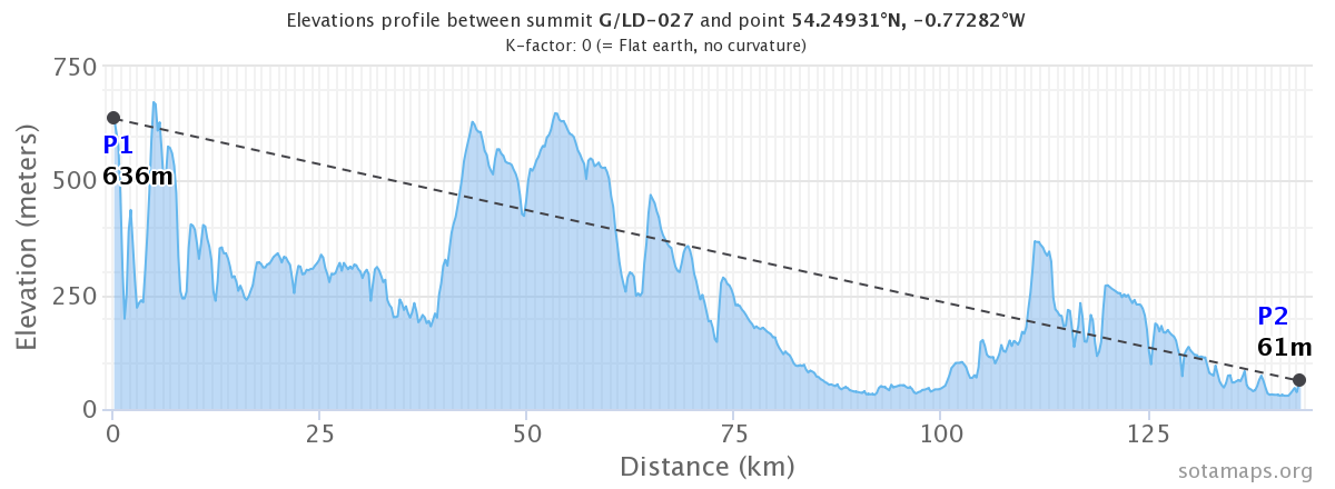
Thank Rob for the plot, interesting and similar to the result I get just viewing a profile when I look at a straight line profile using Memory Map software:
Like Andy I’m as sure as he is that this is Tropscatter. Signals were noisy but fully readable at both ends of the path and we exchanged 44 reports. Without an antenna with some gain at one end I am certain the QSO would not have been made. I regulary work summits in the North Pennines, Lake District and North Wales using this mode and I think the estimate Andy gave of 40% chance of this occurring is a fair estimate as I have listened for Place Fell several times in the past on 2m FM and never made a QSO. I can almost guarantee 100% success for summits near to Place Fell, such as Helvellyn, Fairfield and St Sunday Crag, with stations using 5 watts and the same antenna as Nick & Dave used, however in the case of Place Fell at that end of the path is the Wether Hill ridge (Wainwright summit on the old Roman Road) and that is a touch higher than LD-027 Place Fell and only 5 Km away from there in direct line. I think it is that which makes this such an exceptional QSO on 2m FM.
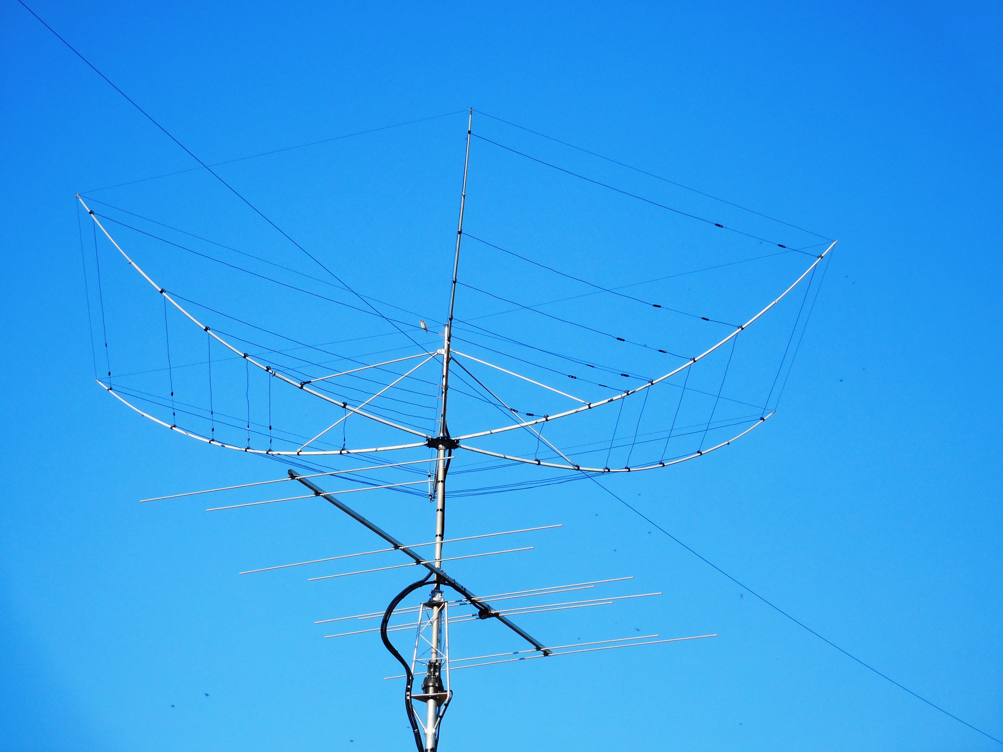
If you are are referrring to the aerial pictured on my QRZ page Rob this is a Hexbeam - several UK SOTA Chasers are using these now. These are much more effective than the cobweb, which I heard called a rotating dummy load, but having never used one I can’t confirm if that is the case!
The Hexbeam is a reasonably effective aerial with similar gain and F/B ratio to a 2 element yagi on 10m through to 20m. I find the Hexbeam is also very good as a receive antenna on the 30m band with low noise, but no use for TX due to a high impedance on that band. The aerial is broadbanded on every band 20m-6m compared to a yagi in my experience, and it matches to 50 ohm coax well without a tuner - SWR is below 1.5 across all bands. It also works reasonably well on 6m but doesn’t have as much gain as the 4m/6m dual band yagi you see pictured underneath it on my mast.
I wonder what the weather/atmospheric conditions were at the time of the QSO.
Yes, I refer to all these types of antenna as a “cobweb” - but actually I could see it in the map when I zoomed into the coordinates you gave - I didn’t think of looking at your QRZ page.
Here’s that profile the other way round, without earth curvature or Fresnel zone, for comparison with your graphic:
Thanks for switching the profile round. My understanding about Fresnel zones was they don’t come much into play on VHF, more MF. Maybe I am wrong. At the time of the QSO yesterday the barometer was 1019 millibars, the air at my end was damp but not misty or wet. At the Place Fell End the ops told me thay were in mist. So plenty of moisture in the air to assist the propagation I reckon.
During this activation Place Fell was covered in low cloud with visibility down to about 15 metres or less. It was very damp, cold - temperature just above freezing level at a guess.
OK, thanks. What I have read online during the research phase behind this profile tool was that RF engineers use Fresnel zones a lot when considering placement of antenna systems for microwave communication and relay stations. They also consider series of Fresnel zones for each significant diffraction point along the path between those stations.
So, the SMP profile tool was put together just as a reference data source, or as an interesting sideline, nothing more.
OK Rob I don’t tend to delve too deeply into the theories of propagation as I’m not clever enough. Tend to just get a decent antenna up, get on the air and see what can be heard, or seen on the screen in the case of FT8 and the like… Good to see EA2EEB on PSK31 today on SOTA EA2/BI-334. He was easy to work once I found his place in the passband.
I recall Fresnel zones come into play in regard to LF/MF propagation especially when a station islocated near to the sea / saltwater. In ON4UNs book on low band DXing, ON4UN says that the ground charactistics within the Fresnel zone will determine the low angle performance of a vertical antenna and how effective the antenna will be, so by improving the radial system within the Fresnel zone it should in effect improve the efficiency of the radiator. I know this is important and indeed having a good ground of counterpoise wires makes a terrific difference - you can never have enough! I didn’t know RF Engineers also referred to Fresnel zones regarding the placement of VHF / Microwave antennae also, that’s interesting.