I try to make a vertical EFHW. Normally about 20m wire is needed to make it resonant on all bands above 40m.
Is it possible to shorten it to 10m by winding a 20m cable around a pvc pipe (4cm diameter maybe)? This will be a loose winding with a very small inductance. (0.6uH)
3 Likes
An interesting idea. I could imagine that a resonance of 7MHz would be achieved if the length and spacing of the turns were varied. However, this will not work at the same time on the higher bands 20/15/10m.
73 Chris
1 Like
Why will it not work on higher bands? The inductance of the coil will be about 0.6uH that is still small for 10m. There will still be a resonance on each band
1 Like
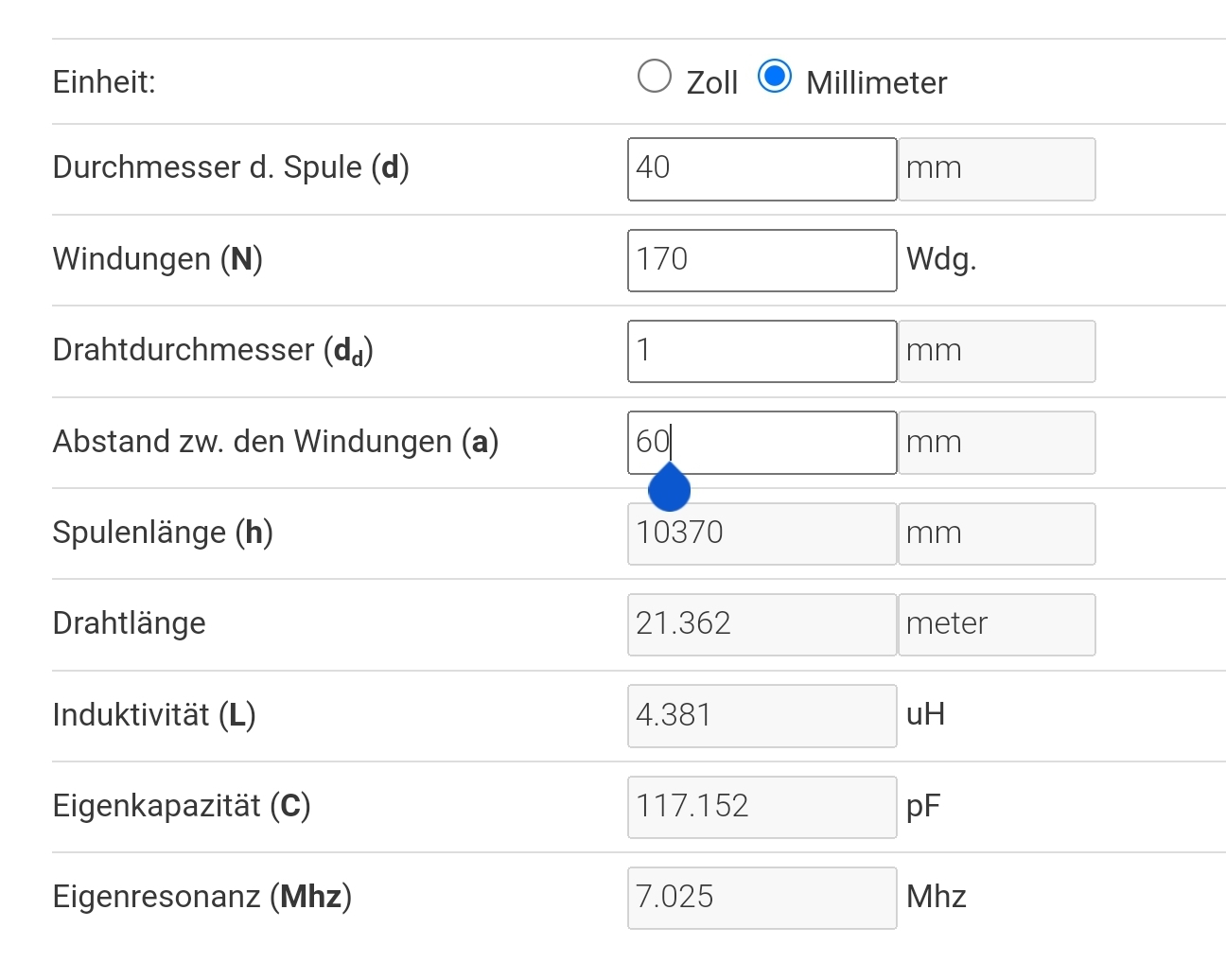
My calculator for the antenna coil shows the following results. Particular attention should be paid to the capacitance between the individual windings. It results in a coil resonance at 7Mhz.
Try it and give us a report.
73Chris
1 Like
Are you sure you mean ALL bands above 40m? Normally, an EFHW antenna made for the 40-meter band as main or principal band will be resonant on 40m, 20m, 15m and 10m, and often with 6m as an additional bonus. On the bands 30m, 17m and 12m such an antenna will be far from resonant, with VSWR values of 20:1 to 40:1 or higher at the antenna.
A VSWR chart of such an antenna (length 20 meters vertical, with 2.5m counterpoise, and a 2µH load in series at 2m above the foot) would look something like this:
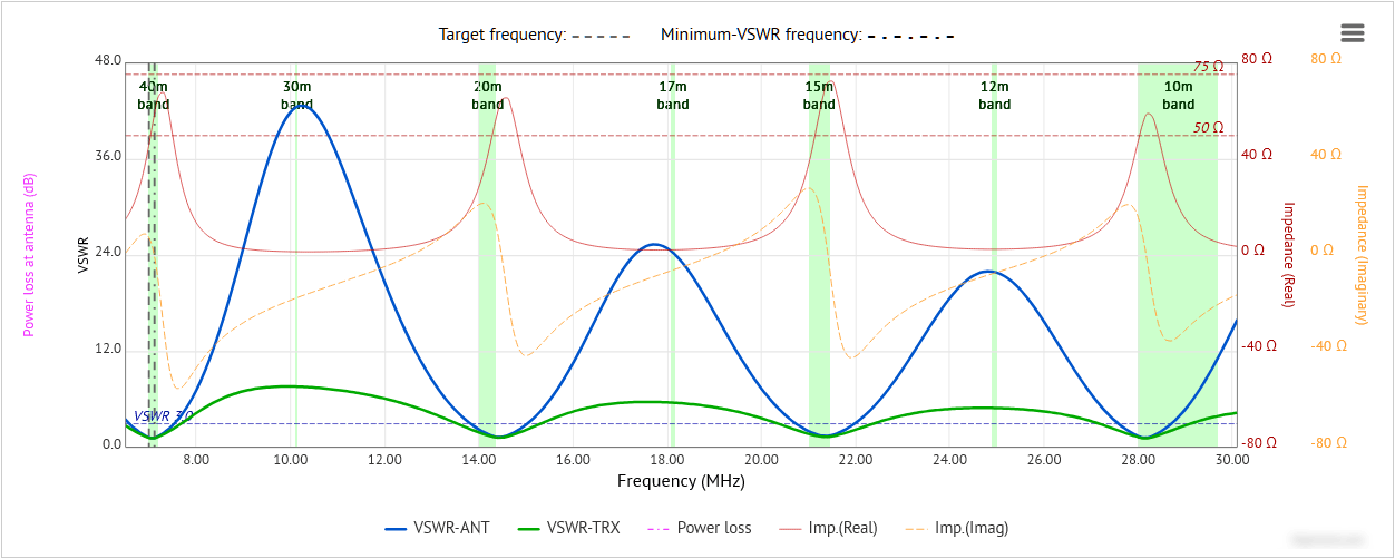
where the blue line shows the VSWR at the antenna.
Of course, there’s no need to keep an EFHW all vertical, you could hang part of it horizontal, or angled to the ground, whatever.
Cheers, Rob
2 Likes
Interesting. My calculator got a much less inductance with almost the same values. Please the link to that calculator. Trust yours more.
However, the resonance given is the resonance of the coil itself (with his self-inductance)
That is not the same as the resonance or resonances of the antenna system. e.g. a straight 20m wire has zero self-inductance but the antenna has a resonance. Or am I getting something wrong here. So if the system is resonant on 40m, you can still expect resonances on multiples.
2 Likes
True, not all bands. but my MMANA simulation shows a low SWR on 17m too. (with a 1:9 unun). The other WARC bands I did not check.
I have also two perpendicular 40m long EFHW and they are resonant on ALL bands above 80m except 60m.
I want it all vertical. EFHW are convenient antennas, but with a chaotic radiation pattern. If you have several you can play with that.
2 Likes
Hello,
I built a shortened efhw. A 64:1 unum, followed by about 10 meters wire, followed by a coil of 25-30 microH, followed by about 2 m wire. The first 10 meters act as a half wave on 14MHz, and a full wave on 10 m band, the coil acting as a choke on 20 and 10 m band. The coil on 7 MHz has a relatively low impedance. On 7 MHz the first 10 meters of wire is a 1/4 wave, followed by the (coil+2m wire)which is a shortened 1/4 wave. Therefore the antenna is working as a efhw on 40 m. The antenna is résonnant on 40/20/10 meters. No résonnance on 21 MHz. I am using it as a sloper, fed at the bottom through the unum, with 2 meters coax. Excellent swr, the antenna as low sensitivity to the quality of the soil, and easy to deploy. The high point of the antenna is a decathlon 6m fishing rod.
73 de Pierre F5MOG
5 Likes
No, I don’t think so.
6 Likes
A straight wire does not enclose any area, so no SELF-inductance.
But the straight wire can be part of an antenna (loop), then there is an inductance. Two different things.
2 Likes
They must have changed the definition of inductance since I did my electronics degree all those years ago. If you wish to believe there is no inductance in a straight wire then be my guest. But you do seem to be out of step with conventional thinking. ![]()
2 Likes
It is also quite long since my degree. But on that one I am pretty sure. Just google: selfinductance of a straight wire. … however, we are both right, just not talking from the same thing. ![]()
1 Like
Inductance (L): The property of an electrical circuit that opposes a change in current, measured in Henry (H).
Self-Inductance: The ability of a circuit or wire to induce a voltage onto itself due to a change in current.
self-inductance of a wire: L = (μ₀μr * π * r²) / length, where μ₀ is the permeability of free space, μr is the relative permeability of the wire material, r is the radius of the wire, and length is the total length of the wire.
In real terms, a 15cm length of #30AWG wire has an inductance of approx 200nH.

(c) Electronics-world 1966
4 Likes
There is an antenna called a “hamstick”, basically a fibreglas core with a coil wound around. This makes it physically shorter than electrical. You can use two butt to butt to make dipole. My line of thought is that if that behaves like a dipole and and EFHW is basically an endfed dipole then I do not see a reason why that should not work.
2 Likes
You are right. It is in most cases negligible, but not zero. Thanks for the refresher ![]()
2 Likes
It’s is a well-known characteristic of an EFHW built for the 80-meter band that it will be close to resonance on all bands 80m through 10m, excepting 60m. By jostling with the wire length and any series inductance one might wish to use to adjust the position of the VSWR minima, the VSWR curve (the blue line) can be brought quite close to resonance on those bands:
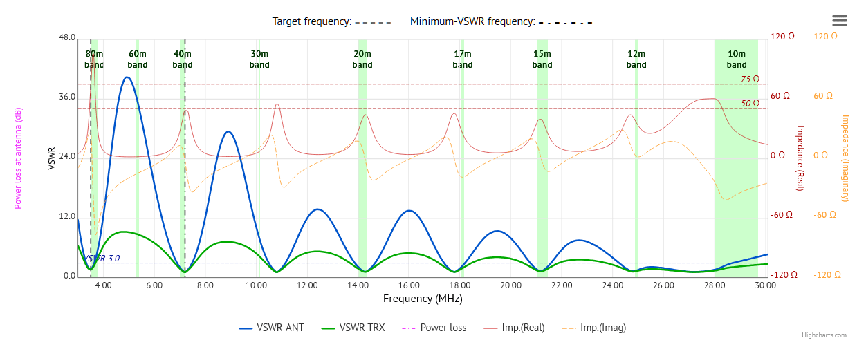
a fact which I still find quite remarkable.
Anybody curious about the green curve in the graphic?
1 Like
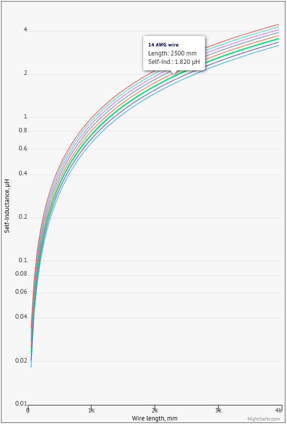
At first view, I thought this was an interesting and useful equation. But after looking at it for a minute or two, I started to wonder whether it could be a realistic expression for self-inductance of a straight conductor. Applying the “look at limits” rule so beloved of engineers and physicists, it would seem that
- if self-inductance really increases as r² then it would become infinite at infinite radius;
- the self-inductance of conductors differing in radius by a factor of n would have self-inductance differing by a factor n² - this is not what the accompanying graph shows (e.g. AWG sizes 10 and 38 would lead to differences of ~600 if the factor of n² were applicable, whereas the graph shows a difference of ~1.4 for a length of 80 inches)
- the formula claims that self-inductance varies as 1/length, which would suggest that a straight conductor of length approaching 0 would have self-inductance approaching infinity, and vice-versa - this makes no sense, and again is not what the graph shows.
So, I looked online (I don’t have an EE or electronics degree) and found a very nice derivation of what the self-inductance of a straight conductor in free space could actually look like:
L = μᵣµ₀ * l / 8π
i.e. which would suggest that self-inductance increases linearly with length l, and that it is independent of the radius.
However, further down in the link given above we have this:
The self inductance of a bare wire is somewhat ill-defined. Well, it is defined, but with some assumptions about the surface over which to integrate the flux, and it scales as l * log (l/r), which makes it’s value per unit length diverge logarithmically when considering an arbitrarily long wire… Once you add [a] second wire, the surface over which you have to integrate the flux is clearly defined, and the inductance of the line scales like l * log (d/r), where d is the distance between the wires. No more logarithmic divergence with respect to l. On the other hand, it depends logarithmically on the distance between the wires, therefore you cannot just assume that the return path is just far enough to be ignored. BTW, the return path is not necessarily a wire, it could be, e.g., a ground plane.
Without looking too closely at the graph, this comment would suggest that the graph may actually follow a similar rule to the l * log (l/r) relationship, as would seem to be borne out by this rough and ready test chart, derived from that relationship, and which resembles that graph rather closely:
It’s an interesting topic, and I’m sure others here, with greater knowledge of such matters than I possess, will weigh in with their own ideas and perspectives.
1 Like
The skill in engineering is not knowing what the formulas are for inductance, capacitance, Ohm’s Law, Kirchoff’s Law etc. but knowing when those formulas no longer apply.
We teach people current in a wire is like water in a pipe. Thicker pipe = more water flow. The same with wire wires carrying current. And it’s a good analogy but you need to enforce the information missing from the simple analogy. “But not at RF where all sorts of extra non-intuitive effects take place.”
In the formula I gave it is for a wire which by definition is something that has significantly more length than diameter. i.e it’s for a wire not an arbitrary cylinder. So as soon as diameter becomes significant compared with the length the formula will break down and be inaccurate if applicable at all.
Here’s another example… The inductance arises because the varying electric current in the wire causes a varying magnetic field around the wire. Lenz’s Law explains why the magnetic field opposes the current flow and the opposing force is known as the inductance. Nothing to do with the shape here. A vary electric field causing an opposing magnetic field. Now the shape is important. We can massively increase the inductance by allowing more of the magnetic field to be close to the conductor. If we wind a coil, we concentrate the magnetic field around the conductor and thus we get more inductance, more of the magnetic field is opposing the current flow. There are formulas for inductance of a coil and they are different to the one for a straight wire. All of them contain a term for the number of turns. More turns means more inductance. So what if there are 0 turns? No inductance obviously. Hey, where have we heard this? Wrong, because the formula is for a coil of wire not a straight wire. When there are no turns the coil formula breaks down. But there are plenty of p**s-poor tutorials online saying just this… a straight wire has no inductance.
But this is patently wrong we just need to look at RF in the real world. The problems with the self inductance of wires become a real problem at VHF and up. The short thin wires you can use for grounding at HF have such inductance that along with parasitic capacitance at VHF and up, the impedance is such that the ground is effectively open circuit. If you look you see wide and thin flat strips used for earthing as the inductance is much lower. Likewise it’s why if you live in a 3rd floor flat/apartment, you cannot just run a 10gauge wire from the shack down to a ground stake… the 10guage wire will appear high impedance/ open circuit at HF due to its self inductance.
And I do object to being told I’m wrong and told to Google stuff when I earned a pretty penny in the past ensuring that many pieces of electrical equipment passed EMC regulations. Something that would not have been possible if I thought straight wires had no inductance.
1 Like
And so you should object - nobody here doubts you know a thing or two about such matters.
But, there’s wrong … and there’s not entirely right. At least to my untrained eye, giving a formula for one thing, and a graph which tells a completely different story would be … not exactly right, unless a detailed explanation is given as to why they differ so much; why, for instance, the formula given cannot be used to derive the graph given.
My $0.02, as always, and I’m sure there’ll be somebody out there who disagrees with me… C’est la vie!
The inductance is “lower” when the strip is bent into gentle curves where necessary, as any lightning-conductor installer will tell you. There’s also the fact that wide and thin flat strips have a greater surface area than round conductors with the same cross-sectional area - this helps not only to dissipate heat more efficiently, but also to ensure a better contact with the earth where the end of the strip is buried.
1 Like
Not exactly but the result is the reducction of the wire lenght in vertical, is the called “17-five antenna” I’ve seen in this video https://youtu.be/ZFRXkeqbSo0?si=rzVHanRIZirpXfea
He manages to reduce the lengh of the wire to 1/4 lambda, in his deployment is 5.33m for 20m band.
That is a non resonnant antenna with a 4:1 UnUn so you need an ATU. Another cons is the use of 7 radials for ground plane.
73, Salva
1 Like