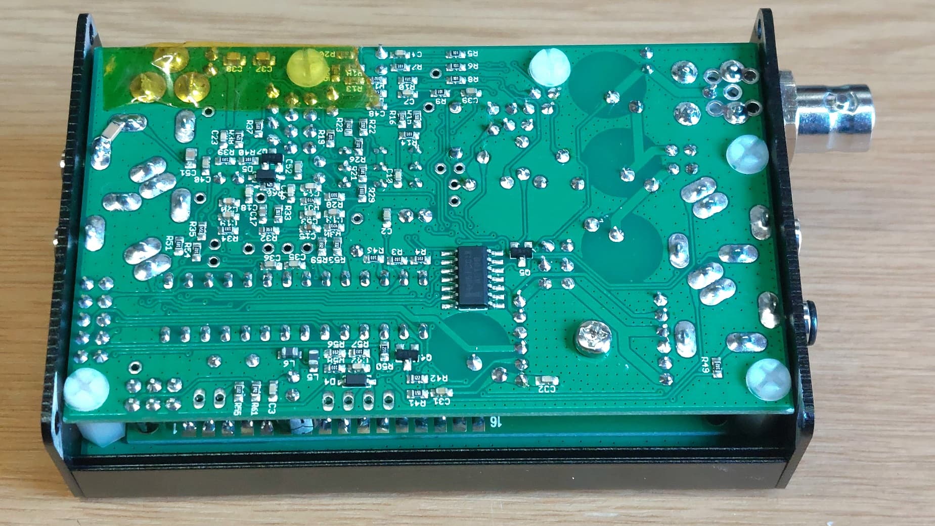
My first time out with my QCXminis for 30m and 20m worked well but I was having RF pickup problems. One cure is to decouple the audio and key lines on the PCB with an few SMD 10n capacitors. I did that but only on the tip lines, doing the ring is a bit harder. I went up Scald Law to test them in anger. WX is nice today so I had to use the overflow car park which adds 4mins to the walk. Managed to get to the trig in 50mins, 46mins climbing. Just acceptable.
I forgot the counterpoise wire. I have an AA5TB tuner to my EFHW. It’s wired with no common Earth so it doesn’t seem to like no counterpoise as the bit of coax can’t be used as one. Bottoms and double bottoms. I had to cobble a counterpoise out of a spare PalmPaddle cable and my 2m J-pole. With them lashed to the Earth post I could get an acceptable match using my home made SWR meter.
SWR was OK but there weren’t any signals. DeutscheWetterdienst was absent on 30m. Something is borked. Turns out my choke balun (10turns on an FT 1143) was open circuit so it was removed. Now the bands had users
RBNhole did its magic. I worked Uli HB9CGA but something was still wrong. Aha!!! The SWR meter is a resistive one. You flick the switch and it puts a 6dB pad in circuit to save your rig whilst tuning up. Yes, Andy, put the switch in to TX when tuning is finished. I worked Uli HB9CGA with about 1.06W into the EFHW rigged as an inverted L with 5m vertical and horizontal bit sloping away to 1m AGL point SE. With the switch in the right position things were better
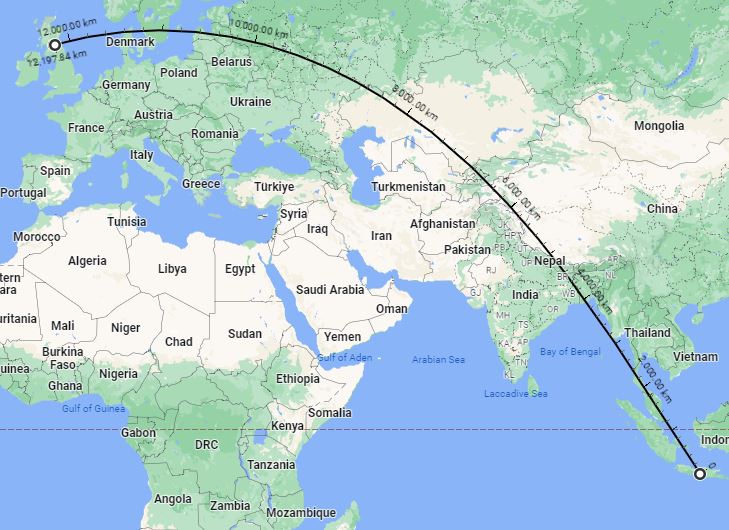
I worked local Europeans using the 20m QCXs. Fred WX1S was loud so that was a nice QSO. Then I tried 30m and worked stations. Then back to 20m. I worked Mark 2M0IIG who is basically at the foot of the hill. It’s good to work locals and nice to hear that Mark and Chris 2M0PVP are both hard at learning CW… good stuff guys. Then some Y???OC called in. There was QSB and QRM but he didn’t sound “right”. I thought it would be YU or YO but no, no and thrice no. It was YC2VOC in Yoyakarta, Indonesia at some 12200km distant. I was modestly pleased with that!
I used a 1.5Ahr “wombled” battery to power the QCXs and the voltage indicator on the QCX is set to show full scale at 12.6V. It was still doing that when I went QRT.
The RF pickup was vastly reduced. Still present but decoupling the ring wires may fix that. It’s 10000% better than last time.
I need to fix the choke balun.
I need to remember to take a counterpoise wire.
I need to remember to take the SWR meter out of circuit when tuned up so I’m not QRPp!
However, once I’d McGuyver’d my way past some showstoppers I have to say that was splendid fun. I can recommend people try some of these QRP CW “Altoids” type radios. It made a nice change from using ready made radios.
I’d post pics but I forgot the camera as well as the counterpoise. But here’s the distance ruler for Edinburgh to Yogyakarta.
I’ve recently added ferrite core chokes to my vertical antennas and the RF feedback problem is vastly improved. I did still manage to invoke a bit of RF feedback in the QCX by moving the headphone lead about. I did try decoupling capacitors back in the day and saw no improvement, I need to revisit the issue sometime.
You’re absolutely correct, having QSOs with a radio you’ve brought to life yourself is much more rewarding than having QSOs with a store bought rig.
I’m not sure if the QCX metal case parts are all electrically connected to the QCX Earth. That would probably help. I used 1206 sized 10n caps. I needed my high gain glasses and a jeweller’s loupe to solder them. It’s a bugger this getting old… you finally have enough cash so you don’t have to work but you can no longer see anything. And your expensive hifi sounds like AM radio
This is the first time I read/hear about vagrant RF affecting the QCXmini.
I have the QCXmini for 60/30/17m (and a SW-3b for 40/30/20m). I have also built an endfed with traps for each of these units with their bands. The QCXminis I then simply change…it is the same antenna.
The antenna including the feed wire is in one piece with me (and at the end of the antenna wire I have a few meters of string to pull it over a branch or mast).
From the BNC connector the RG 174 goes about half a meter and then there is a current balun (W1JR) on an Amidon 114-43. Then I have the RG 174 about 0.05 lambda of the lowest band up to the transfomating balun… This I wound with 0.2mm enamelled copper wire on an Amidon 82-43 and soldered a 100pF C in parallel to the output of the RG 174.
Then I built all the traps and determined the length of the individual sections for the respective bands with the NANOVNA and soldered the traps after the respective measurement.
So bring the antenna wire for the highest band in resonance and then solder the trap. Then extend the antenna wire, determine the resonance for the next band and solder in the trap… etc.
I have done the whole thing on the yard on the telescopic mast as Inv - V and the SWR is well below 1.5 on all bands. It changes slightly depending on the setup of the antenna.
I have found that the antenna wire length, the 1:49 balun, the RG 174 cable length with current balun always form one unit.
I have several baluns 1:49 always wound the same… and always provided with the same C and put in an old plastic film can. I have different length coax cables with a power balun and some cut to length antenna wires for the same bands.
As soon as I change only one of these components, the resonant frequency changes.
There’s no current choke/balun on mine. Never needed it or saw any adverse effects using the 817 with the antenna. I have one I made a while back but as I said, it has gone open circuit when I went to use it. It’s one of today’s tasks to fix it, probably the fault will be at a connector.
Without a choke and with both 30 and 20m QCXs close to the start of the EFHW, the feedback was severe on their 1st outing. I found wrapping the paddle cable around my hand reduced the pickup. I had a look in the QRP Labs groups.io pages and found the suggestion of 10n capacitors to decouple the headphones and paddle inputs. They have made difference and I have only decoupled the tip connection to Earth so far. You could hear the tone on transmit sound a little rough now where before it was badly distorted. I really should complete the job decoupling the ring connection but there wasn’t any convenient earthy place by the ring connection on the sockets, might be easier with a wire ended 10n but there is a need to keep the wires short. I still feel a bit of sanding the paint back in strategic places so the case components are all bonded at low impedance to the outer of the antenna socket would help.
Fixing things like this is part of the process in using home made radios (even though these are kits). I’ve done this work in the past professionally making in-vitro medical electronics pass CE EMC tests, both radiated and conducted emissions and susceptibility. I used to visit a test house where the measurement facility was about 190m underground in the disused part of a Salt Mine.
I always thought during my first SOTA activities that I don’t need a current balun.
The first activities I had with an IC 703 which has a good antenna tuner on a 1:9 Unun antenna with 16,5 m. In addition I dragged my Bencher on the mountains. … then the Bencher began to give independently points and lines in the change.
In the www was also to be read that this is a well-known error by direct irradiation of the HF and one should connect the ground connection of the key directly with the housing of the IC 703.
This also helped well… but it became really good after I connected a current balun in front of the antenna input.
Since then I have it as standard in all antenna cables.
My coax fed dipoles have a current choke at the feed point, makes a difference in my experience. I’ve now tested the current choke on the bench. Perfect continuity. I also shook it about whilst measuring and it was fine so no intermittent connection. That makes me think another connector is not right. More bench testing needed.
No! A dipole is a balanced antenna so if you feed it with coax you definitely need a balun/common mode choke. Plus you can never be sure it really is perfectly balanced.
I use EFHW and GP antennas for SOTA. I have found that a common mode choke does make a difference (but not always). In some situations it even makes a difference which end of coax the choke is. This is specifically with a multiband GP - there will be radiation from the radials which are quite close to the operating position.
I have Andy’s problem, somebody stole the cymbals from my favourite drummers kit. A mate said “use your hearing aid” - I hate the dam’ things, but I gave it a try. Once I had found a comfortable position for the headphones I tried listening…but now the dam’ cymbals drown out the music! You just can’t win!
Off topic, sorry, but surely there could be a configurable processor to put in line with headphones for listening to music? - rather like the Wolfwave that is made for CW etc, but a quick google didn’t find anything…
(No hearing aids yet, but definitely heading that way!)
I totally agree,
A common mode choke filter of approximately 500Ohms reactance (10 times the feed impedance) at the operating frequency, although not always necessary with a dipole. is good practice. It is reliable, effective and easy to implement. Using link dipoles (with a choke balun at the feedpoint) elevated to 6m and RG58 feeder, I have never experienced RF feedback issues up to 100W RF.
By comparison the EFHW generates ground current. Just what we do not want for high aerial efficiency and prevention of EMC issues!
If I wear headphones with mine they oscillate - can’t win.
But then mine are only there to replace everything above 6 kHz where my hearing is 80 dB down
I usually use dipoles but I think part of the issue is the external leads picking up the RF field and feeding it in to the radio. With SOTA we tend to be physically close to the antenna. I guess is SOTA ops put our gear through extreme conditions. I’m guessing that the majority of QCX kits won’t actually make it out into the field
Get yourself a de-wax and you’ll find it much better. I’m still good for around 15kHz without one, but I know plenty that have lost their top that are younger than I am.
Well done on the results with the QCX. Good to see you are showing the big guns that life isn’t too short for QRP.
I was on Wether Law that day with my own 20m QCX and an EFHW set up as an inverted L but I didn’t get nearly as good results as you did. I’m going to have to buy you a coffee and bend your ear about how you managed it.
Still, got my CW and HF activator badges on the same outing, and less than ideal results today leave lots of room for improvement next time.
I have used the QCX 20 mini on approximately 10 peaks, some with large collections of RF services mounted on towers. The radio seems to handle that environment surprisingly well. Antenna is always a 1/4 wave ground plane vert. with 2 to 3 1/4 wave gnd plane wire. No hint of RF feedback into the radio. No tuners, baluns, required.
I stuck on a 10nF cap to my headphone socket (tip and ring are tied together) to try it. I also grounded the case parts, but the rig now seems microphonic. Will have to see how it goes in the field.