Radiation diagrams EFHW 20m long

I am still very convinced of my 20m long EFHW. Today I took out the radiation diagrams that I calculated some time ago. As with many activations, the conditions are as follows. The entry point with the 1:64 unun (or rather RF transformer) is approx. 3m high, the end point is usually 6-7m and hangs on a rope in the tree.
In the diagrams, the entry point is in the center, the end point on the right side at 90 degrees.
What is surprising for 14MHz is the fairly flat radiation with gain at 90 °
But see for yourself.

73

2 Likes

I’ve been using a 20-meter long EFHW on my sota tours for several years now. It’s actually a dipole cut for the 40-meter band.
The performance on the 20 meter band is fantastic. Since then I have always made a good amount of QSO’s on that band, despite the poor propagation. It is common to make QSOs with the USA or Canada.
I put it in an inverted V on a 9 meter rod. With the ends one meter off the ground.
Highly recommended.

Juan

1 Like

Hello Chris

Thanks for sharing the information. I am also using this version of Endfed for 7,10 and 14 MHz with a 1:64 transformer using a 4C65 core material.
What does your transformer look like? Because of the relatively low permability of the core I use compared to an Amidon 43 the 4C65 needs more windings. So the performance of my transformer is only usable up to 14 MHz with low SWR. I cannot operate it on 21 or 28 MHz. The nice side is, the 4C65 is less lossy within the range defined above.
I hope to hear you again soon from a summit in your area. It is the perfect distance from here to DM/NS … for a contact on 40 m.

73
Peter

Hi Peter,
nice to read that you also use the 20m version of EFHW.

Since I got my license in 2013, I have my first experience in the sunspot maximum phase. With the 5 watts from the FT-817 I was able to make a lot of DX connections at 10m. Here is my range record.

And so I was heard.

Always with the EFHW with Amidon 43 Unun and portable.
With the openings at 28MHz, which are very rare at the moment, this is still an advantage. I gladly accept the losses of 1-2db.

See you soon, I’m looking forward to our next contact.

Greetings to Sylvia,

Chris

2 Likes

Hi Jean,

the theory fully confirms your experience with EFHW as inverted V. The radiation diagram shows radiation in all directions at a flat angle.

73 Chris

Lars, SA4BLM asks me today which unun I am using. Here is a picture of the circuit and construction.

I do not currently use the black connection (ground) and the gray connection (50 Ohm). Also for 3.5Mhz I connect the antenna wire to 2.8 kOhm (red) and use the antenna tuner from KX2.

So it can be qrv on all bands from 80m to 10m, including 60m, 30m, 17m and 12m without changing the plug.

73 Chris

1 Like

I would be very cautious about what sort of capacitor that you use. The type in the photo looks like a type that is not suitable for RF. If so, it will be very lossy. In that application you need a proper RF capacitor for best results.

1 Like

Richard,
I agree, that looks like a ceramic disc capacitor vs a Mica capacitor which is better suited for the application. My first 49:1 unun used a ceramic and though it worked the swr would rise with power rise. I swapped that capacitor for a mica capacitor and problem went away. Also, the SWR across the band flattened out to a constant 1:2 :1 vs the 1.2 to 1.6 variance I previously had.

And now for the shameless plug: The capacitors are readily available via SOTA BEAMS.

It’s the same type Yaesu use in the tuner of my FT-450 running 100 Watts.

73 Chris

Im confused. You indicated that the one in your matching unit was rated at 500 Volts and the one in the photo above is clearly not in a tuner and is rated at 2kV. The general point is that the dielectric is the key factor and tiny caps with very high voltage ratings don’t usually have a dielectric that will handle much RF current without heating up and their value changing. If yours works then fine!

The reason that I know there are potential problems is that I built such a matching unit and found that the C got hot! Professional experience suggests skimping on Cs is a bad idea.

3 Likes

I also am confused. I have had a sleepless night thinking about this.

If the wire is 20 m long then the following is the (very) approximate end impedance.

RF Wavelength Wire length in waves End feed impedance Approximate Z
80m 1/4 wavelength Low 50Ohms
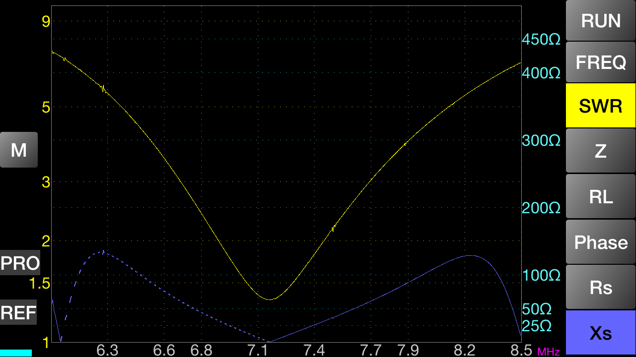
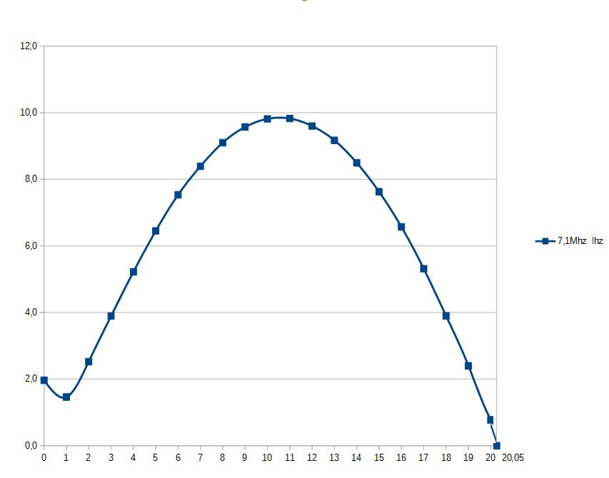
40m 1/2 wavelength High 2700Ohms
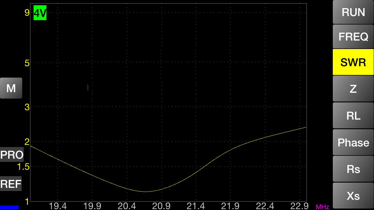
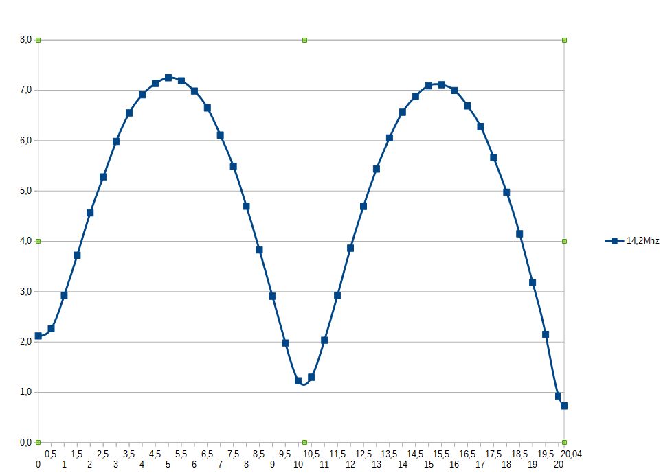
20m 1 wavelength Low 200Ohms
15m 1 1/2 wavelengths Med 700Ohms reactive
10m 2 wavelengths Low 100Ohms

So what do we get if this wire is fed with a good match?

On 80m we have a low height quarter wave, we should expect high angle radiation but some dB loss compared to a dipole because of the unbalance.

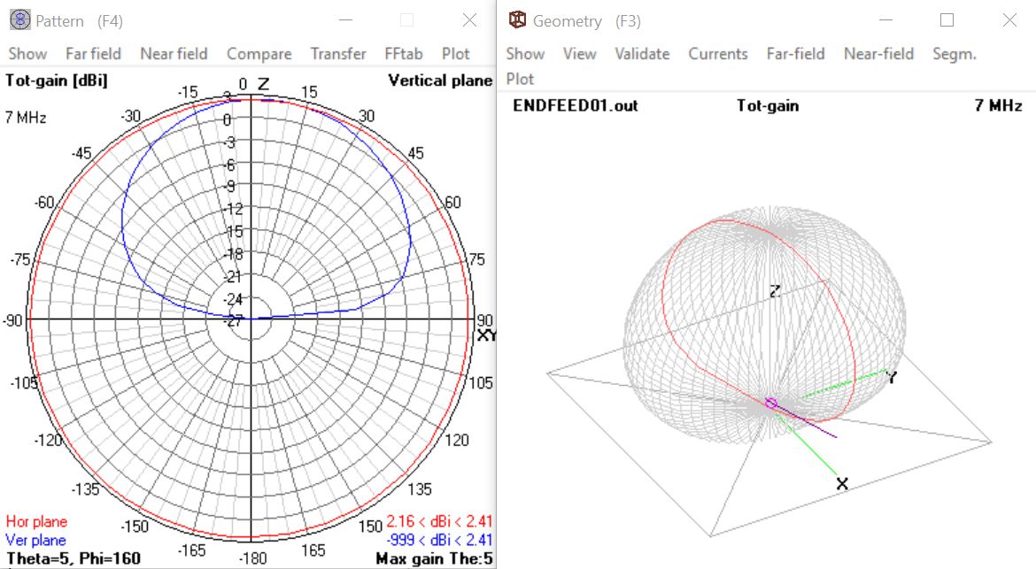
On 40m we have an end fed half wave, the feed impedance is high and because of the low height we should expect high angle radiation.

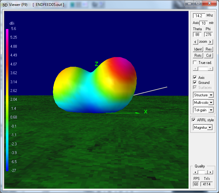
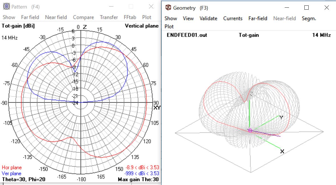
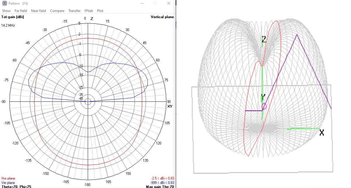
On 20m we have a full wave aerial, the vertical radiation is suppressed and end fire is supported, we have gain towards the horizon.

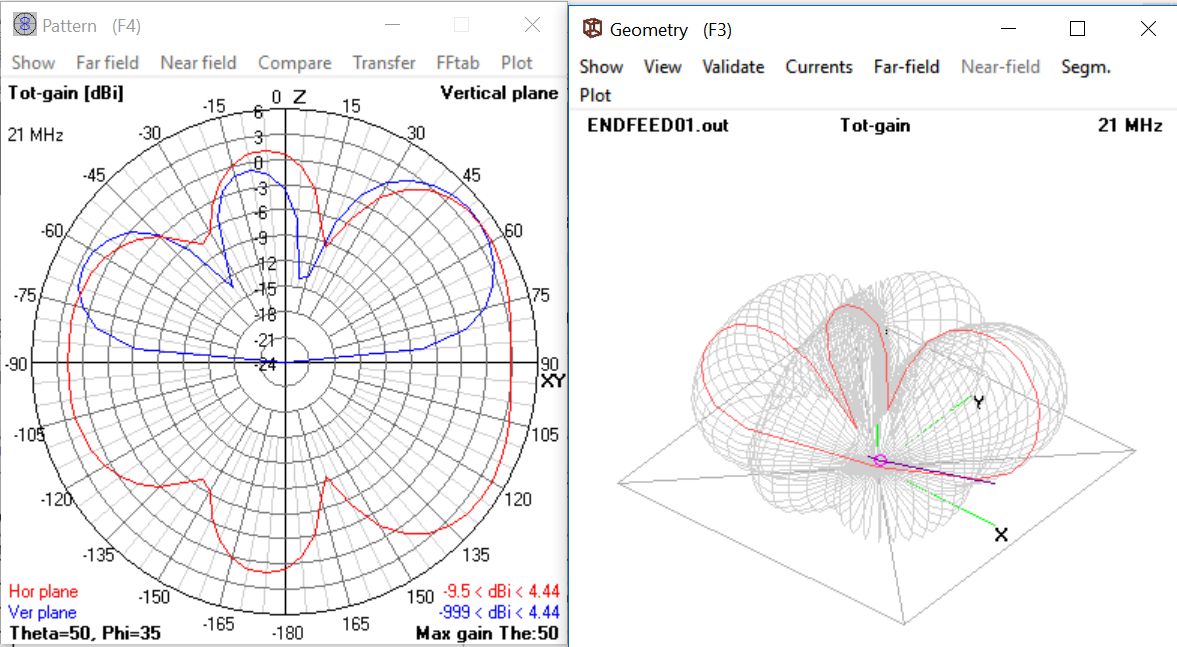
On 15m we do not have a clear picture, the impedance is moderately high and reactive. again the vertical radiation is suppressed and end fire is supported, we have gain on the horizon.

On 10m we have 2 wavelengths and a lowish feed impedance the vertical radiation is suppressed and end fire is supported, we have gain on the horizon.

So provided we can align the wire, we can enhance the DX radiation on 20, 15 and 10 m.

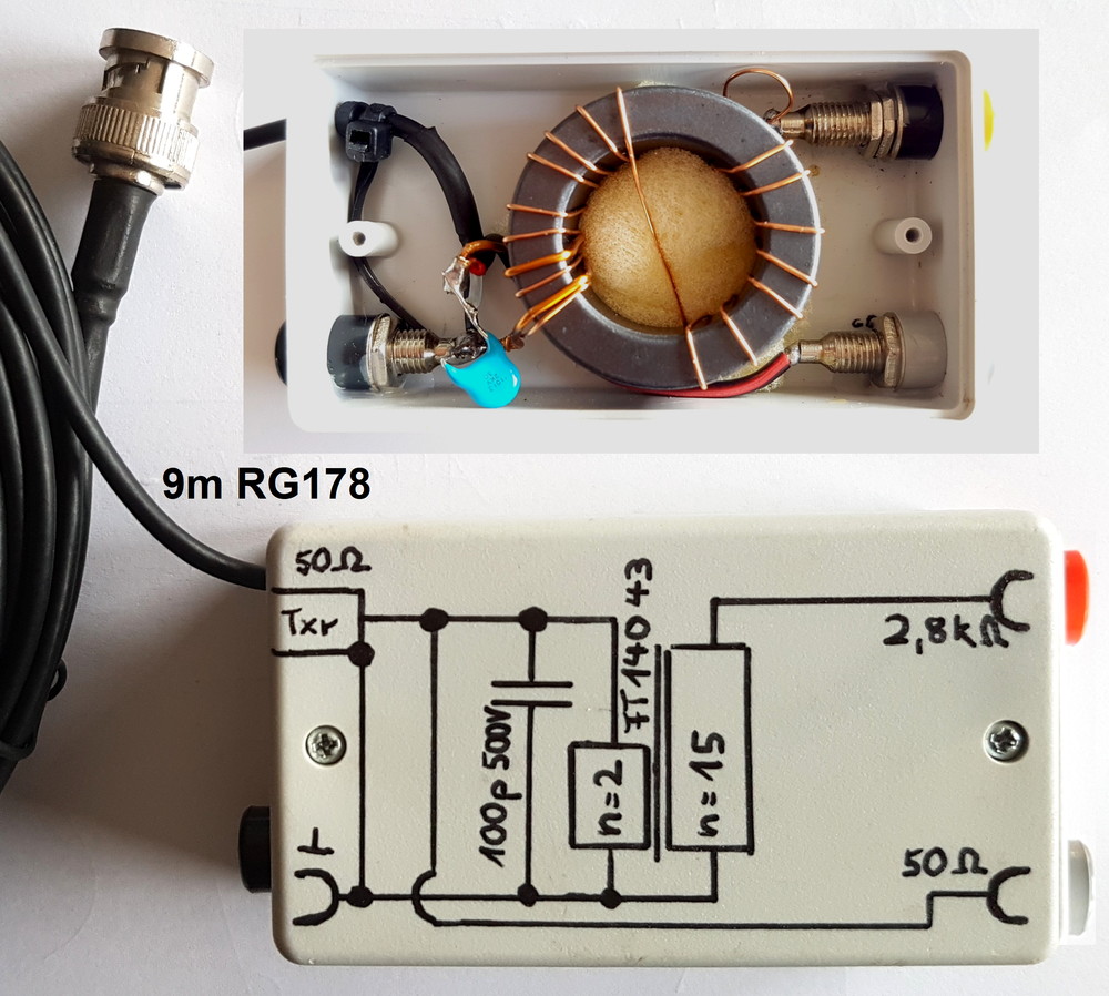
Then we come to the Transmission Line transformer.

It is difficult to see how a fixed transmission line transformer can convert these very different feed impedance to a low SWR for the rig to feed it across 80 - 10m.

Looking at the circuit I have some questions:

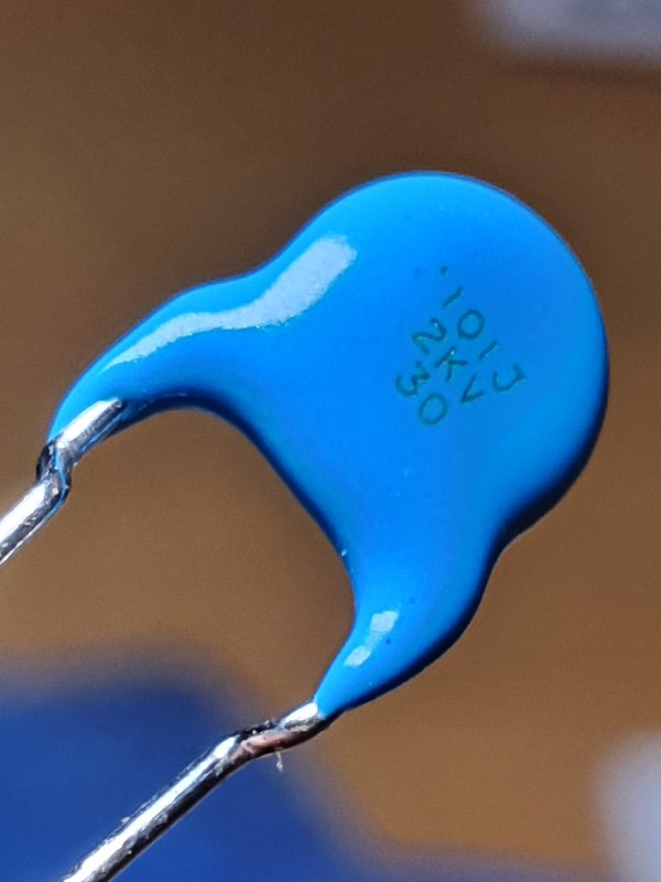
I do not see the purpose of the capacitor, is this to tune the primary of the transformer to resonance on one band?
In my experience transmission line transformers rely on tight windings of bi-filar, tri-filar or higher order to maximize the inter-coil capacitance and enough turns to achieve inductive coupling at the lowest frequency in use. The core only acting as a magnetic coupler.

So looking at the photograph it looks as though we have a 2 turn primary loosely coupled to a possible 2/3 turn secondary, connected to a 13 turn inductor. The crossover connection is also unexpected. This device is often used on choke baluns to reduce the input/output leakage capacitance. I cannot understand its purpose here. At 10 W the peak voltage on the end of the wire is about 250V peak, does the insulation on the torroid needs some consideration?

All that said, the 20m long EFHW for 14MHz does intrigue me. I usually use inverted vee link dipoles that are resonant on each band of choice. Having an end fire wire on 20m would be a worthwhile addition to the rucksack. I just need to get my head around feeding the wire. It is certainly much simpler and probably out performs an elevated Ground Plane in the chosen direction.

Regards
David G0EVV

1 Like

Hi David

Concerning feedpoint impedance of the end fed antenna I agree with you looking at 80 m and 40m band. And you are right, twisting the 2 primary windings of the transformer improves the performance.
For 20 m and 10m the antenna length is an even multiple of a half wave wire, so the voltage and current dirtibution along the wire repeats and voltage is maximum, current minimum at the feedpoint resulting in a high impedance.

73
Peter

Thank you for your interest and the detailed comments. I would like to say more about this, but I don’t have the time at the moment

Here, however, are 4 SWR measurement diagrams from the antenna described. In addition, there are 3 diagrams showing the RF current along the 20m wire. I determined the value with a very small portable RF meter I built myself.

Maybe that brings more clarity.


73 Chris

Peter, thanks for the support.

I have not yet found any conclusive information about the twisting of the two primary turns.

I assume that the wrapping should be simplified in this way.

73 Chris