I was convinced to buy this antenna because of its low price, otherwise I wouldn’t have done it. I knew it could be a dud, and indeed it was. It’s terribly dull. Have any of you managed to improve it? 73 IW2EPE

2 Likes
Hi Luca,
These “Magic” antennas are, as you say, a disappointment; however, ignore the telescopic whip and add a length of wire instead (plus a counterpoise wire), and they’re not half bad at matching/tuning and End-Fed random or half-wave antenna as they (normally) consist of a variable inductor within the small case.
73 Ed DD5LP.
5 Likes
Why?
I had that type of antenna on my CB radio handheld in the early 70s when I was 12. It could at least reach around the next corner of a house… and sometimes in the summer we even heard foreign stations with it… but we never actually had a QSO with them!
But we thought it was magic! ![]() … and great
… and great
73 Armin
4 Likes
IT WAS! and still is!
2 Likes
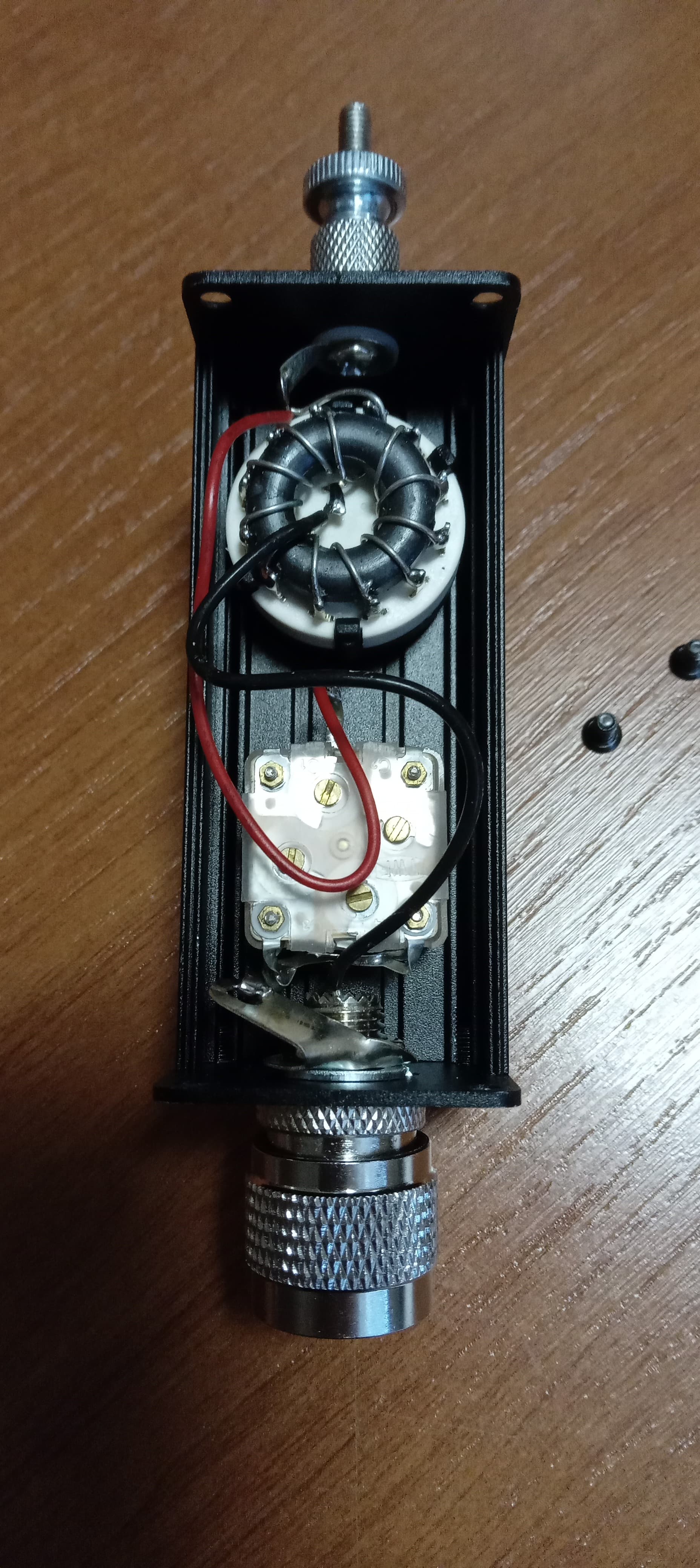
The internal circuit is very simple, but the wire connections are terrible. Perhaps it could be modified to make a single-band.
73 IW2EPE Luca
1 Like
I also bought one of these antennas. For me, it works fine electrically. It’s just as loud as such a short antenna can be. The radial wire that comes with it is very important.
73, Peter - HB9PJT
2 Likes
What is wrong with them? They look reasonably smooth and shiny in the photo, they don’t look “dry”.
My opinion is that they are too long. 73 IW2EPE Luca
I didn’t find any radial thread in the package. 73 Luke
You can connect any wire as a radial. The wire I received with the antenna is 7.12 m long. For the 20-10 m bands, a length of 3.50 m might be better.
The wiring according to your picture is fine with me. Shortening the wires will not make any difference.
73, Peter - HB9PJT
1 Like
so with 7.12 m of wire you work 40 m. as a counterpoise how many meters? 73 IW2EPE
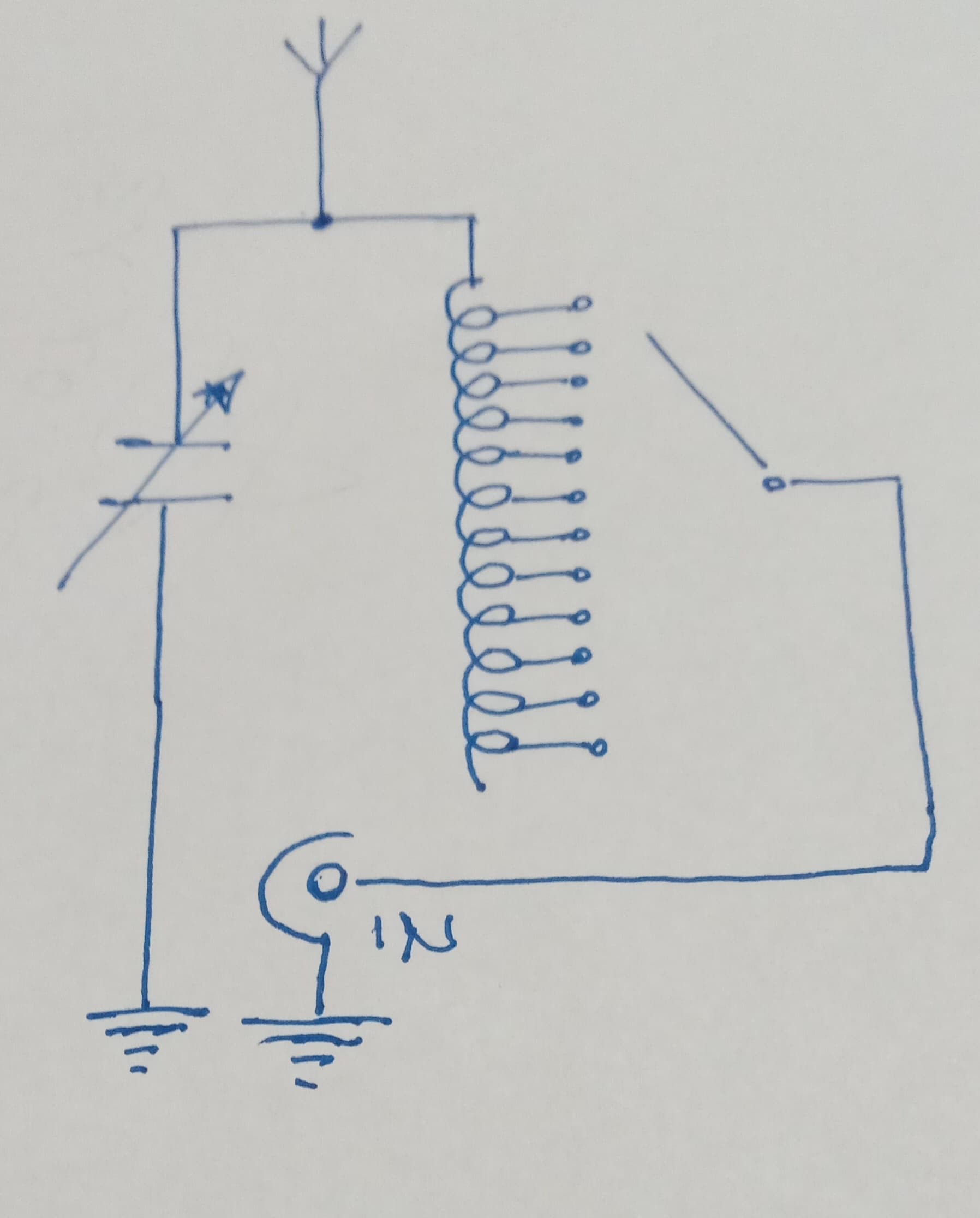
If you look at the diagram I drew which represents the internal wiring, it might represent a wrong wiring If you look at the diagram I drew, which shows the internal wiring, it might be incorrect. In my opinion, the capacitor shouldn’t be connected to ground, but to the center of the switch. Comments are appreciated. Thanks. 73 Luca
1 Like
It’s an L-match with the capacitor on the output side. That configuration is used when the load impedance is greater than the source impedance. You can connect the capacitor in the input side for when the load impedance is less than the source impedance.
2 Likes
How much is the impedance of a 1.4 m stylus? Generally, the impedance of an 8 m wire is 500 ohms. 73 Luca
As DD5LP said.
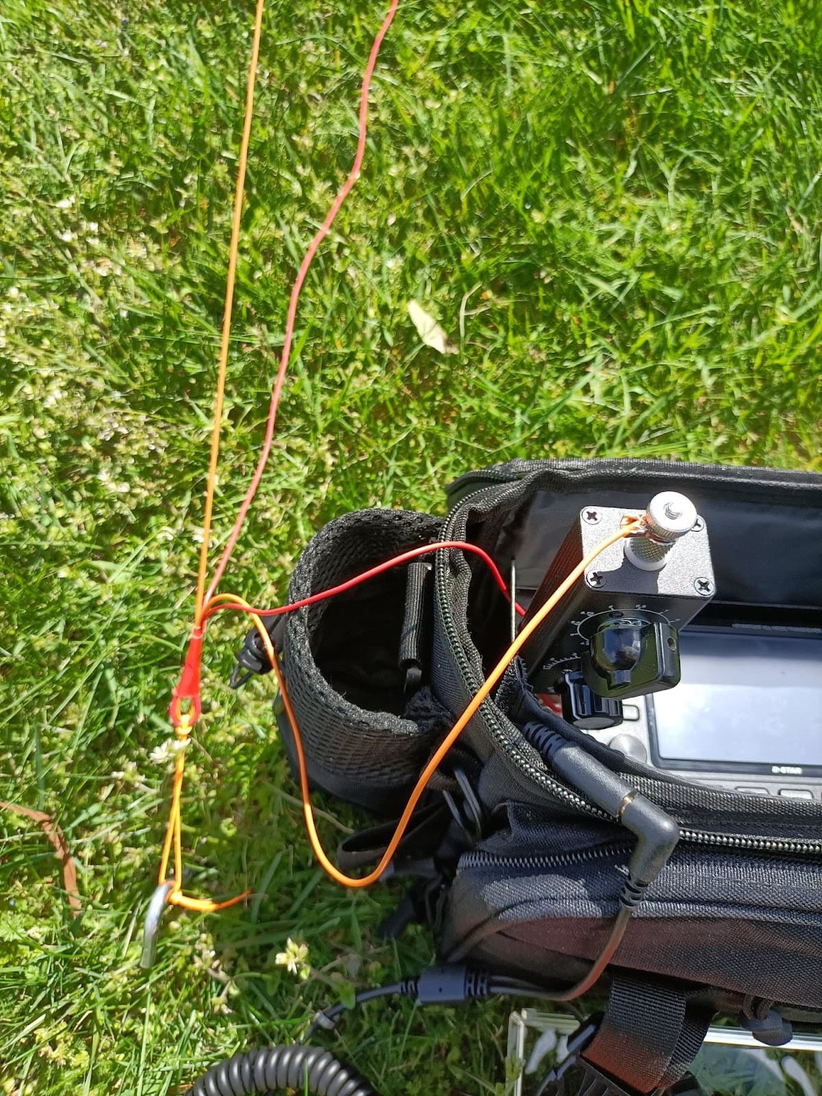
Here is mine set up in the field attached to my IC-705 tuning a random wire sloper.
Works reasonably well.
Cheers
Phil ZL3CC
3 Likes
Hi Phil, how many meters are your two wires? 73 Luca
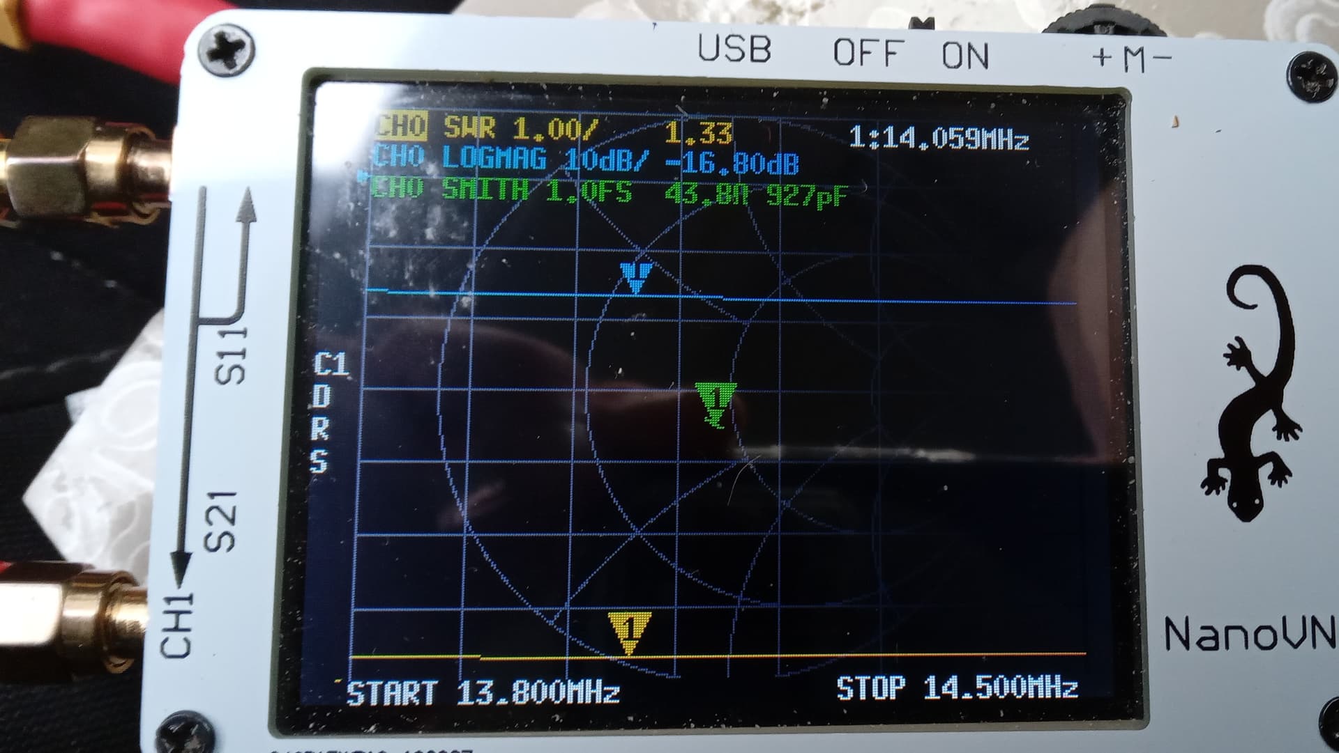
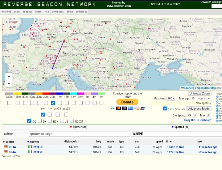
Today during my lunch break I quickly tested the antenna with magnetic base on the roof of my office car park. 1.4m whip with no counterpoise. 20m band, 3w. Switch position 5. I haven’t checked the propagation; RBN has returned two contacts to the same radio station in Germany. At least I have proof that something is radiating.
73 Luca
1 Like
Lucsa,
In that particular photo I was using 25’ radiator and 25’ counterpoise, much the same dimensions as the SOTABeam Band Springer. However, I have used it wth radiator lengths from 18’ to 84’ all giving varying but reasonable results; mostly the variation coming from the environment - especially ground composition and choice of setup. My usual goto is 84’ radiator and 17’ counterpoise in an inverted ‘V’ or a lazy sloper into a tree. In most circumstances I try to keep the ends at least a metre off the ground.
Cheers
Phil ZL3CC
Yes but please dont expect that your signal would be loud enough for “normal” QSOs as DR4W is “above-avarage” RBN…
73!
Peter DL3NAA
1 Like
I agree.
73