Wow!! 
Where can I find the project?
The idea for this project came from the Ham Radio Duo “Just OK Mini” antenna, but i made some improvements:
- I put a BNC connector for direct connection to the QMX
- I added a beta match for impedance matching which is necessary when using a raised radial
The antenna works without beta match with a radial very close to the ground or on the ground, but the losses are significantly higher in such configuration. That’s why I decided to use a raised radial, which, in addition to greater efficiency, also gives me better impedance stability because the influence of the ground is significantly reduced. In such a configuration, beta match is necessary because the impedance of the antenna in my case is around 12 ohms.
The length of the radial is about 4m, but I made a simple system so that I can adjust the length, and thus fine-tune the resonance of the antenna. Basically, it is a kind of dipole, so by adjusting the length of one arm, the resonance changes.
I can share the STL file if anyone wants, but I’m not sure if it will be useful to you because I’m using a BNC connector from an old Tektronix oscilloscope probe. It was on hand and seemed like the best quality solution, but unfortunately it’s not available unless you have such an old probe somewhere.
73 de Ivan, 9A7AM
5 Likes
Yes please, that would be great to have a look at.
It could be reasonably simple to make an enclosure for a BNC connector. Someone will have the skills to do something mega I’m sure.
1 Like
I can send the stl file to anyone interested by email. You can find my email address at qrz.com.
73, Ivan, 9A7AM
I see in the photo that you are using an elevated radial.
This produces the sharp resonance point—indicating low damping—and contributes significantly to the radiation pattern, effectively acting as a much longer antenna element.
73 Chris
4 Likes
Yes, it is essentially an L-dipole. The efficiency of this antenna is significantly higher than with radials on the ground, and also for handheld operation the impedance and SWR are significantly more stable and repeatable considering that I am working without an antenna tuner.
73, Ivan
3 Likes
It is indeed interesting to see how the arrangement of radials affects the resulting radiation characteristics of short vertical antennas.
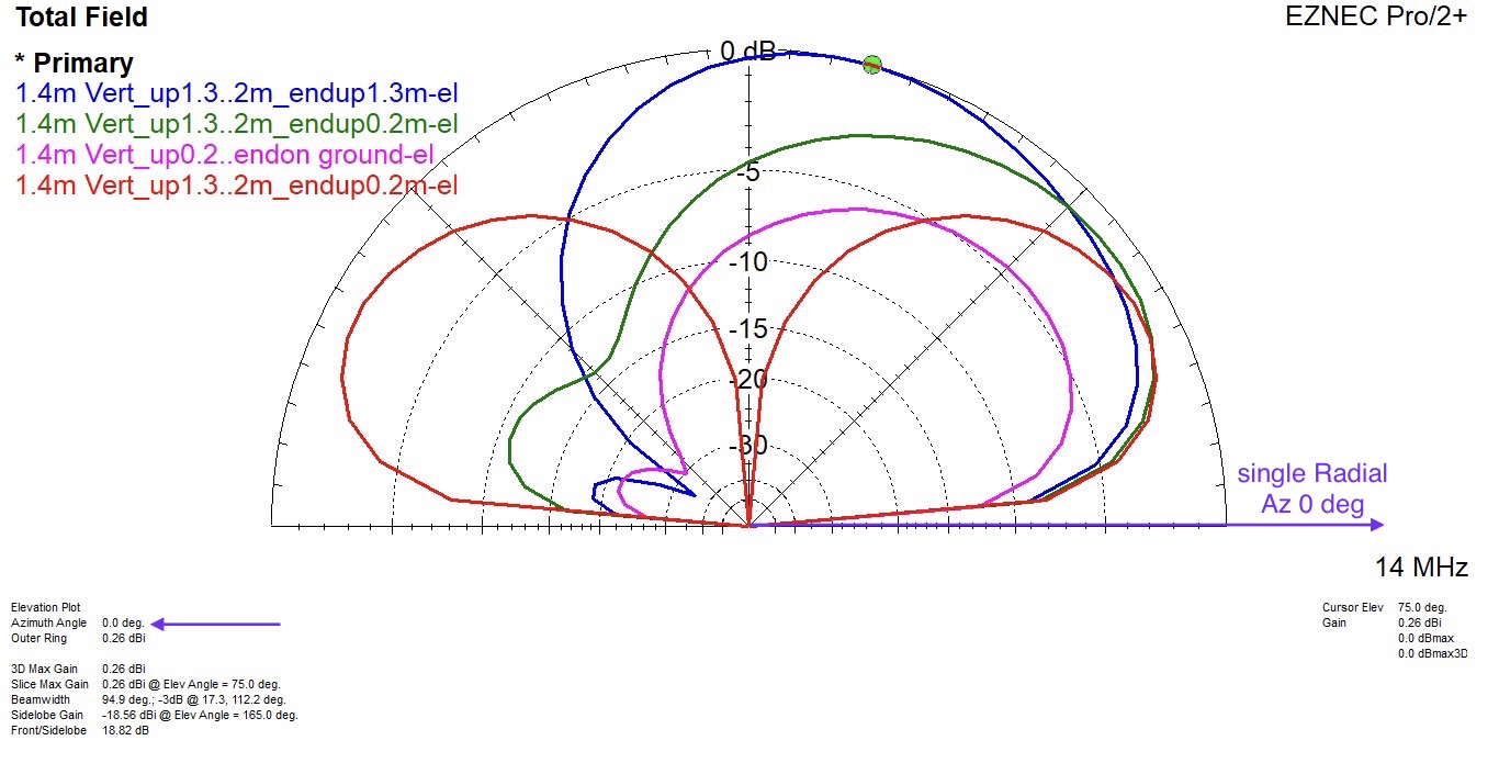
The EZNEC graph below shows the resulting vertical radiation pattern of a 1.4 m whip antenna with a 4.2 m radial in the following configurations:
- Whip and radial end both raised to 1.3 m
- Whip raised to 1.3 m, radial end at 0.2 m
- Whip raised to 0.2 m, radial laid on the ground
- Whip antenna raised to 1.3 m, ends of 2 radials at 0.2 m (used with my whip antennas)
7 Likes
Two radials are always a better choice, but unfortunately they are not practical for handheld operation.
I have done WSPR tests for these three configurations with one radial and the results I got match your EZNEC simulation. The antenna with the radial almost on the ground was on average 5 to 7 dB worse than the antenna with the horizontal radial and the slanted radial.
The slanted radial gave me the most reports from DX stations, and the horizontal radial was slightly better for me at the European level.
73, Ivan
2 Likes
Which direction is the lobe in relation to the radial?
What happens to the lobe with the whip at angles other than vertical.
73 Pete
The slice with the maximum radiation is at an azimuth of 0 degrees, which is also the orientation of the single radial (added to the EZNEC plot above).
Tilting the vertical antenna towards the single radial (e.g. by ~33 deg) results in a slightly more symmetrical radiation, but at the cost of maximum gain.
Vertical antennas with 2 opposing radials of equal length radiate omnidirectionally (-> the orientation of the radial pair is irrelevant, which allows more freedom when setting up the antenna).
73, Heinz
1 Like