QCX Mini - QC WARNING

A Warning Concerning The New QCX Mini

Based on personal experience and a number of posts on the QRP Labs group, there are people who are having issues with cracked SMD components on the main PCB. I personal have experienced a cracked SMD component I noticed when I did second look at the board after reading about issues others are having.

If you do not have experience with or equipment to carry out component level SMD replacement, you may want to think twice about building this as a kit, and purchase a pre-assembled device.

image

1 Like

That seems rather extreme advice when there may be a QC issue that has been located and will be resolved.

4 Likes

As I said, IF YOU DO NOT HAVE EXPERIENCE. If you feel comfortable doing rework on SMD components, by all means have at it. I do not, nor do I have the proper equipment. Iā€™m just relaying my experience and what others have posted on the group. People can do with this information what they will, and I would hope they would research it. This is one persons opinion and as they say, ā€œeveryone has one.ā€ :slight_smile:

1 Like

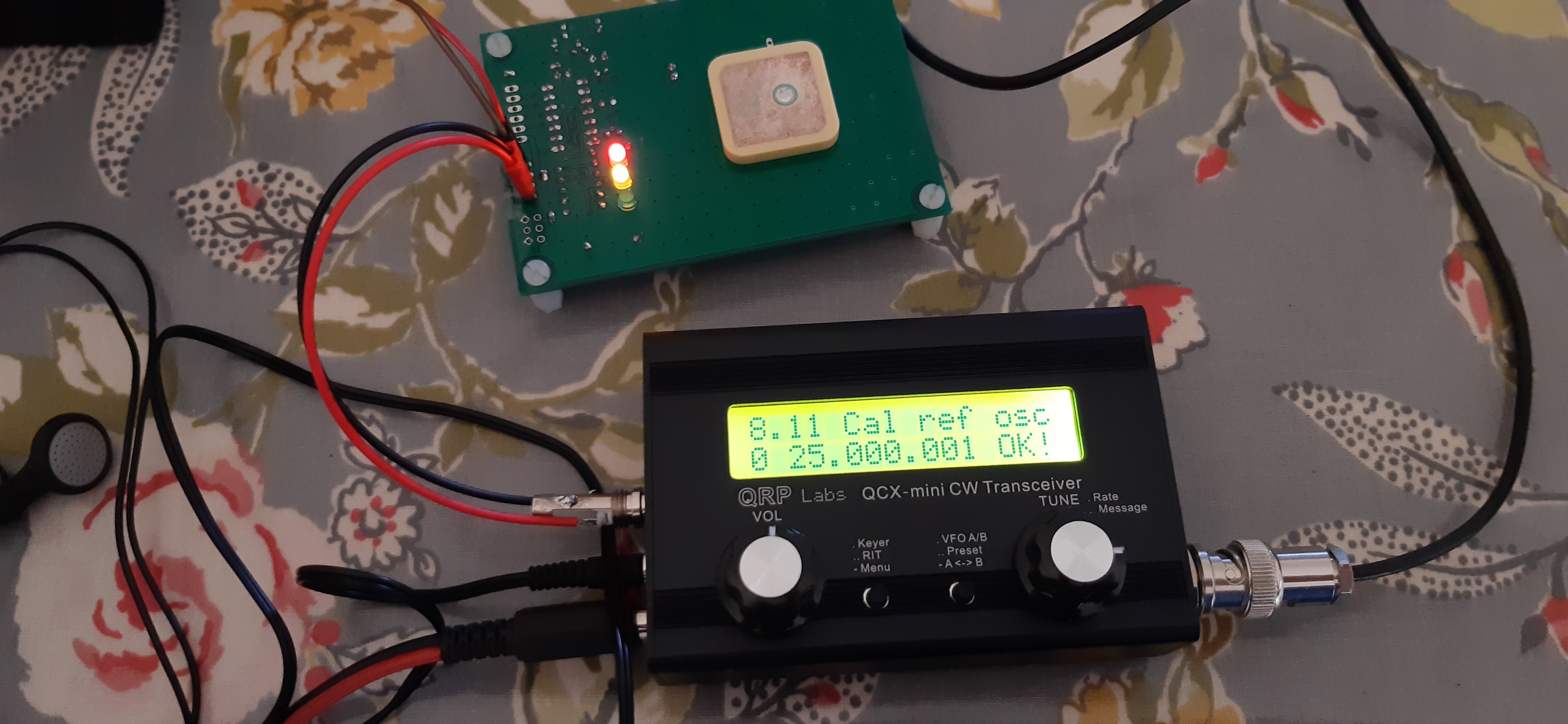
Last night, I assembled my 4th QCX-mini, this one for 20m. On power-up it worked flawlessly; alignment was text-book, and the power output 4.6W at 12V supply rising to over 6W at 13.8V supply. On inspection prior to commencing the assembly, I found no cracked components, poorly soldered SMD etc. Everything looked perfect, as it did with the three previous kits I assembled (all from this first production batch).

After assembly this QCX-mini, I proceeded to undertake a detailed examination of 10 QCX-mini kit PCBs with a x40 Jewellerā€™s Loupe. In all 10 cases, the soldering was perfect and there were no cracked components, poor joints, or any evidence of hand-soldered rework.

This is a sample of 14. It does not guarantee that 100% of the production batch are fine. In any production batch, yield may be less than 100%.

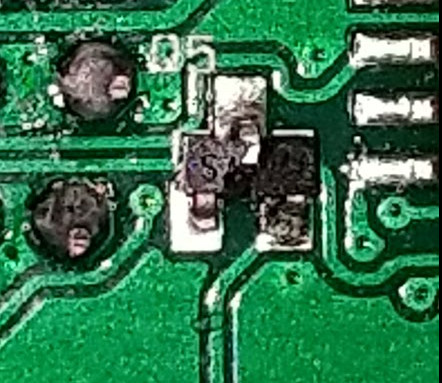
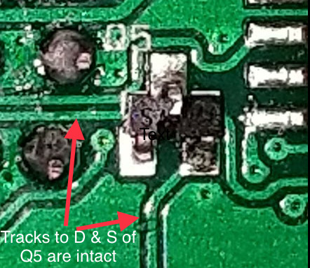
Regarding the cracked component in the photo shown, do not forget, that as in some other examples, this cracked component was found on an assembled board, during investigation of why the kit did not work. It is quite possible that some other assembly error caused the destruction of this component when the unit was powered. A physically cracked transistor is quite a common thing when they overheat. We just donā€™t know the circumstances leading to that cracked component. Iā€™m just making the point that it may not be anything to do with a manufacturing error.

Of course I am also watching developments closely and always striving to improve the products and production, if there is any QC problem then we will find ways to improve this in future.

The assembly manual does clearly contain a paragraph, before commencing the assembly, suggesting a careful visual inspection before starting. I have also stated that in the event of any manufacturing defect, QRP Labs will of course consider it normal to provide a replacement board, just contact us.

SMD work is completely possible without any equipment. I have none here, either. It just takes good light, some optical assistance, with a good dose of care and patience. All of the prototypes were built with my regular 936D clone 60W iron with, believe it or not, a 3mm chisel bit. All it takes is patience and bravery.

Generally: if you damage (via assembly or operating error, etc) a small portable unit of such small size like this, then yes, if you need to replace anything, you would quite likely need to replace SMD components. This is the nature of the beast. Itā€™s small, because it uses SMD. There is no difference here, to if we are talking about an Elecraft KX2 or KX3, FT817/8 etc. I intentionally kept the SMD components in the QCX-mini no smaller than 0603 and SOIC pitch ICs wherever possible, specifically to make it reasonably easy to undertake repairs if any turn out to be necessary.

For people who prefer something a bit larger, with all through-hole components, all kit assembled, the QCX+ has the same schematic, performance, firmware and features, in a larger format see QCX+ 5W CW transceiver kit .

73 Hans G0UPL, QCX-series designer

12 Likes

Like I told you Hans, I NEARLY broke an SMD component when holding my side cutter too flat to the board. I just caught myself before committing the crime ā€¦
But it is quite easy to get an SMD part between the back of a side cutter (where one does not look), and while cutting a wire, break the SMD as well.
Also not accusing anyone of doing it, just want to send out a warning to be VERY careful.
(I added the warning to my blog, see other thread on this reflector)

Luc ON7DQ

Your Q5 receives only 1.4mA from the 10k resistor via 14v power supply.
That ā€œcracked Q5ā€ with such a magnitude which blows away the potted compound at the SOT-23 die, can only be done by a large current of few amps to the drain and source or maybe a C5 chargeā€¦ :cold_face:
Please note that both copper tracks from Source and Drain of Q5 are still intact and Q5 is not misaligned with the silk print.

Cheers, 73 Pascal
image

SMT and more experienced hams :no_mouth:. Its impossible ya know :grimacing:

Sot23, plenty of flux and a single soldering iron. Its just practiceā€¦ really.

Hi Pascal, Luke

Yes Pascal, I am not trying to say that there are no manufacturing problems, and all defects are the fault of the constructor. In this instance yes, Q5 should pass only a small current. If every component is working properly, installed and connected properly, then the whole circuit MUST function correctly. But as we know, this is not always the case - sometimes there are assembly errors, and in a smaller proportion of cases, component or board defects, and then all is not as it should be.

What I am trying to say is that there are more possible reasons for such defects, than manufacturing problems alone. Electrical failure due to some mistake or other, is one possibility (not necessarily likely in this particular photo). As Luc pointed out, it is also quite easy to damage a nearby SMD component when cutting off the wires of a through-hole component you just installed. I already cautioned in my manual to be very careful when soldering through-hole joints because the joint can be close to SMD components. Damage during shipping is another possibility, I am convinced some postmen play football with packages.

There are lots of possibilities, not all are manufacturer problems - we should keep an open mind. In the 14 boards I have personally examined, all 14 were perfect. This is not rigorous statistics but at least gives some warmer feeling about the situation.

If anyone does experience a defective board or component and does not have the means or parts or will to resolve it themselves, then the remedy remains as it has always been during the 10 year life of QRP Labs: contact me and I will sort out a replacement.

73 Hans G0UPL

3 Likes

Iā€™ve just started building my Mini today. I thoroughly examined the board under good lighting beforehand and all the SMD components looked correct.

Having completed a QCX+ recently the Mini does need more care. Its not that the components you need to fit are smaller, they are not and most are identical to the QCX+ components, they are just fitted much closer together and often very close to the pre-installed SMD items.

Examining each completed joint under a strong hand lens is essential, especially those close to any SMD component. It would be very easy to create a solder bridge.

I also found it essential to turn the board around frequently so the soldering iron approached joints from a safe angle without touching a component already fitted. I rarely had to do this building the QCX+ but with the Mini you must.

Snipping off the excess wire from components needs to done with extra care, again approaching with the snippers from a safe angle which avoids snipping out something else on the board. :slight_smile:

Iā€™m not for a moment suggesting this was what caused the damage shown at the start of this thread. Iā€™ve only just started building it but having completed a QCX+ the Mini doesnā€™t require any different skills - but you do need to take more care and folk shouldnā€™t be put off the kit.

2 Likes

Hi John,

Thanks for the feedback. I agree completely, itā€™s nothing new, it IS a matter of more care, because there isnā€™t a lot of space and everything fits together with very close tolerances.

In the beginning, there was QCX. But some people said the board component density was too high. Many found it difficult to install it in an enclosure because the controls and LCD all ended up at different heights. BaMaTech (German firm) solved that with the aid of a set of machined extenders for the rotary controls and buttons.

In May 2020 I released QCX+ which was my attempt to listen to some of that feedback. The board is over 2x the area, all resistors are lying flat, and thereā€™s just generally a lot more space. There are pin headers to make it easy to modify, a Dev kit to easily add your own modifications, TCXO option for the WSPR-inclined and the type of fellow who always gets the leather steering wheel option and all the other extras in his new car. And the beautiful enclosure into which QCX+ fits like a glove.

Then came more feedback from, well, ya know, the SOTA gangā€¦ saying QCX was nicer than QCX+, because it was smaller and lighter and because the format (display and controls on top) was more suited for portable ops. I didnā€™t really like going back on having moved forward (my own psychological fault, presumably) so went further and the result is the really small QCX-mini. Weighing in at just over 200 grams and with half the current consumption of QCX/QCX+ and a sunlight readable display.

But yesā€¦ as a result of being small, QCX-mini is, well, smallā€¦ very cute though, and we have lots of mountains around down here in South West Turkey. Just wish I had time to go walk on some!

73 Hans G0UPL

8 Likes

I just finished mine, I have a issue with audio for a IC10, hope changing It the problem will fix

1 Like

Good luck!
I had to change IC9 on my Mini.

Iā€™m looking forward to trying my rig once lockdown is over, although naturally Iā€™m a little worried about it failing in a puff of smoke!

I swapped the spurious 5v regulator and used a genuine Texas Instruments one instead.

Fingers and toes crossed!

73, Colin

2 Likes

Hi Colin, is that the QRP labs GPS module connected to the QCX?
Does the GPS take its power from the radio or external power?Thanks
Tim G4YTD

Hi Tim,

Yes, the GPS in the picture is the QRP Labs QLG1.

The GLG1 requires a 5V supply, I found the 5V inconvenient, so I built a dedicated 5V regulator module to power the unit, along with itā€™s usual pairing of the VFO kit. I use the GPS/VFO as a frequency standard. (I canā€™t afford a fancy standard!)

I ā€˜borrowedā€™ the GPS module to calibrate my QCX-mini. I simply made up a quick and dirty interface lead using a JST-RCY lipo cable and a salvaged 3.5mm stereo plug. As the GPS module has itā€™s own power supply module, I didnā€™t need to connect anything else.

The QCX-mini has a PTT socket, which is intended to supply a 5V switching signal for the optional QCX 50w amplifier. It is possible, with extreme care, to use the 5v rail to power the GPS.
It is important to be aware that there are risks in doing this. The 5v regulator is quite vulnerable. The advice is to never hot-swap anything.

Hope this helps.

Colin

1 Like

Hi Colin,
Thank you.
I have finished my QCX, it is running 30m with 3.2w output at 12v, so happy with that for now.
Next job is the GPS board, hopefully if other commitments allow, it should be up and running at the weekend. just had a quick work-from-home look in the jubk box and have a 7805 so will cobble something together to power it up. Thanks for the advice, and the hot swap tip.
73
Tim

2 Likes

Second that. Iā€™m running my 17m mini as a WSPR beacon and have no issues pulling 5v off the PTT but make absolutely sure that there is no power when I unplug the GPS module.

Sounds, almost, Biblical.
Dermy VK1DB