Almost finished a few days ago. Now some fine tuning (output power) is still missing. Another QCX that has been brought to life here 
73 Marcel DM3FAM
Almost finished a few days ago. Now some fine tuning (output power) is still missing. Another QCX that has been brought to life here
73 Marcel DM3FAM
@DM3FAM
Hi Marcel, you have been added to my “Hall of Fame” … I have added a paragraph in my blog post about making an extension cable like yours. Thanks for the excellent idea !
Luc ON7DQ
Hello Luc @ON7DQ.
I had problems measuring and checking without the extension cable. Now I have enough space. Interesting blog from you. I have already found some good information. Thank you very much. See you in the next QSO.
73 Marcel DM3FAM
Today I did some tuning of the toroids in my 17m QCX Mini.
I changed only L4 and L3, and could raise the power to 5.6W (at 12V DC input).
Power on 20m is now 4W.
Luc ON7DQ
My QCX-mini is still W-I-P. I keep telling myself that I’m having fun! In truth, I’m looking forward to having the completed rig.
Colin
Hi all,
just in time for the end of 2020, I posted some measurements on my QCX Mini.
I started a new post because the first one was already quite long.
Read it all here:
Enjoy, and … Happy New Year !
Luc ON7DQ
Fantastic Luc,
looks like my next purchase will be a QCX Mini for 17m; two bands for the price of one. I use a Fuchs antenna (with my small CW only rigs) so I should get some additional harmonic suppression.
73 de OE6FEG
Matt
Luc, the measurements you are reporting are much more than Han’s claims. For example, with a 12v supply he says 3W is the expected output.
My measurements, based on the voltage at a 50 ohm dummy load, also show 3W with a 12v supply. Both my 20m QCX and 40m Mini give the same result.
I haven’t done anything to the LPF toroids yet because the power output seemed to correspond with what QRP Labs said I should expect. Perhaps I need to re-think.
Well Matt, @OE6FEG
It looks like you can read my mind.
I was just testing a lightweight Fuchs antenna for 20m and 17m, hi.
It’s hanging indoor now, from the attic along the staircase, to the ground floor, but seems to work OK. Only I took a high brightness LED, and it is on all the time with 5W, maybe I should take an old LED, or put a Tiny SWR in the tuner.
I will take it outdoors as soon as I can, and do some tests with it.
I made the wire 7.9m for 17m, and adding some 2.20 m should make it work for 20m. My tuner circuit resonates on both bands, and even on 21 MHz, but I don’t have a QCX for that  (yet !) .
HNY es 73
Luc ON7DQ
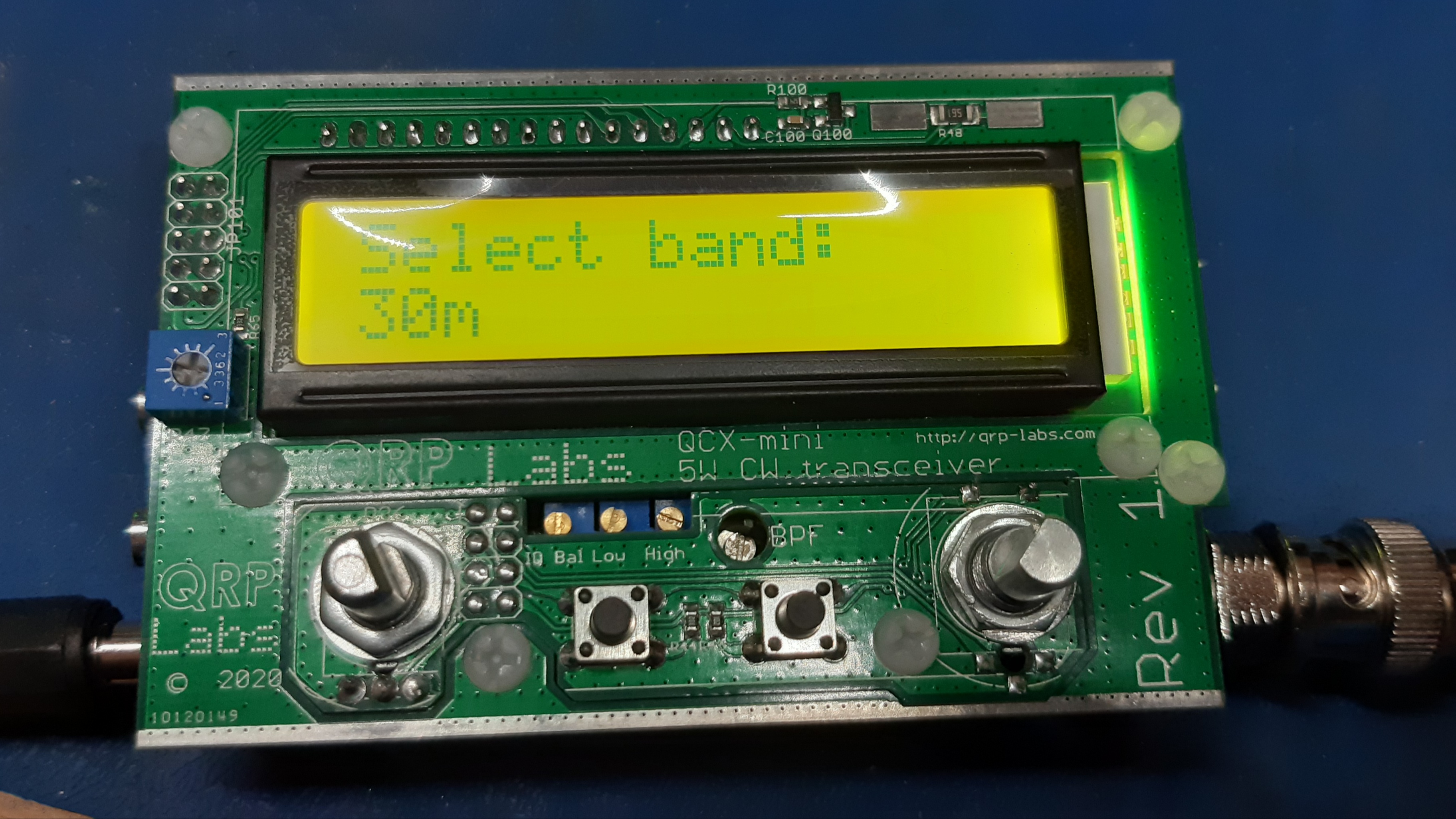
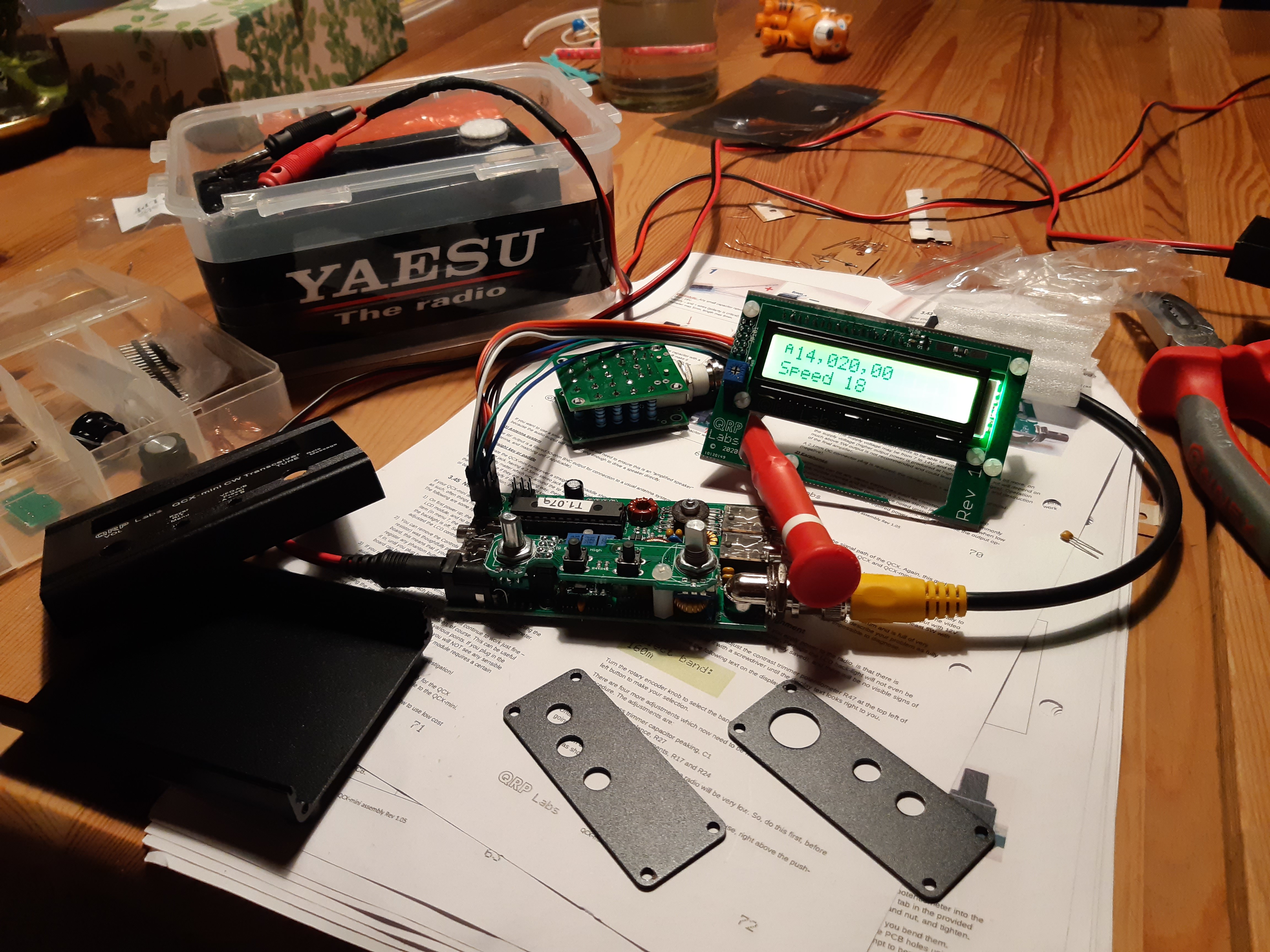
Well, I finished my QCX-mini build but despite taking much care, the rig is not working
Thankfully the smoke test went okay, however I’m stuck at the alignment so far. I suspect that I’m suffering from the dead op-amp issue that seems to be fairly prevalent. I do have some NE5532 in SOIC-8 that I bought for a project on my long ‘to do’ list.
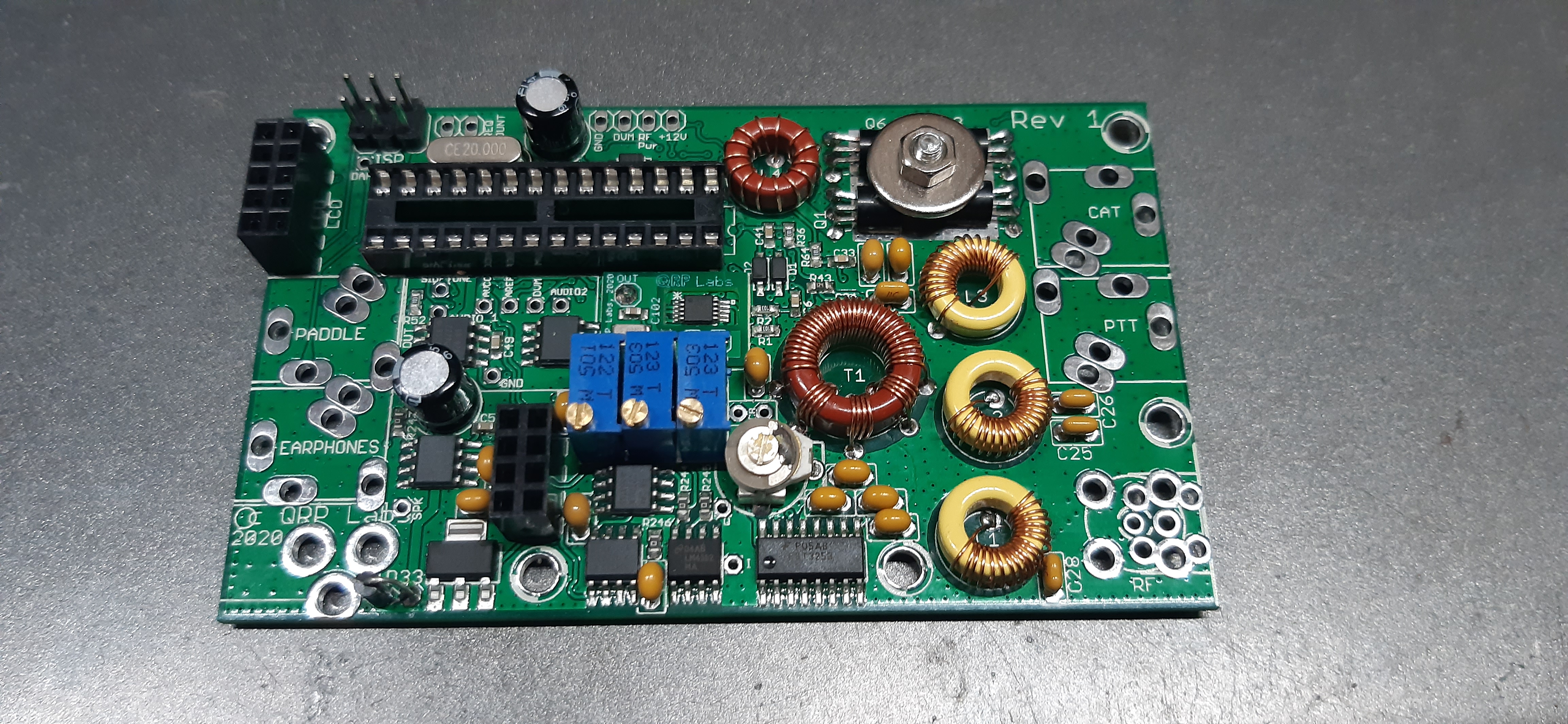
In terms of power output, I’m getting 4.6 watts output at 12v on 30m. I adjusted the toroid windings for max output but I didn’t remove any turns. I suspect that if I removed a turn from the toroid nearest the PA stage, I’d see a bit more power but I’m happy with what i have.
Hopefully I’ll track down my receiver issue soon, either with a DVM or firing up the ancient Tek’ 465.
Colin
According to the video Hans made, you should get about 4 watts out at 12V, although he ends up with about 4.5 watts after some tinkering:

I would definitely advise you to play with the toroids, 3 watts seems low to me. Luc has done very well to get over 5 watts.
73 Matt
Thank you, I haven’t seen that video - it is really helpful.
I went through the procedure on my QCX 80, and whilst I did squeeze an extra watt out at 12V, the change was not as dramatic as with the higher band kits. My guess is that Hans got a bit sick of people complaining about low TX  . Something else that is useful to know, is that if you move the CW filter centre frequency, as detailed in the modifications, it is very likely that you will see a lower peak (below 7) when you come to peak the BPF. However, there is nothing fundmentally wrong with the RX.
73 Matt
Hi all
The power curves in the manual were measured back in August 2017 with the original classic QCX. The schematic and performance of the QCX+ and QCX-mini are substantially the same.
Now the expected power output is generally higher due to:
Since January 2020 we have been using only micrometals toroids supplied via http://kitsandparts.com - these generally provide slightly better performance than the previous toroids.
Since January 2020 we have been using only Vishay NP0 capacitors sourced via Digikey US - particularly on higher bands these capacitors have lower loss than the previous NP0 capacitors used.
I learned how to better adjust for best power output, and documented it on the YouTube video ![]()
After these three improvements (incl #3 tuneup if necessary), you should be within 1/2 a Watt of 5W at 12V supply, sometimes more than 5W; and by 13.8V you’re really cooking.
Note that the purpose of the 12mm washer is NOT to act as a heatsink. It is a very poor heatsink because it has very little contact area with the transistors (actually ZERO contact area since their curved surface touches the washer. The purpose of the washer is to apply force to the transistors to firmly secure their flat side against the PCB groundplane. The PCB groundplane is the intended heatsink.
73 Hans G0UPL
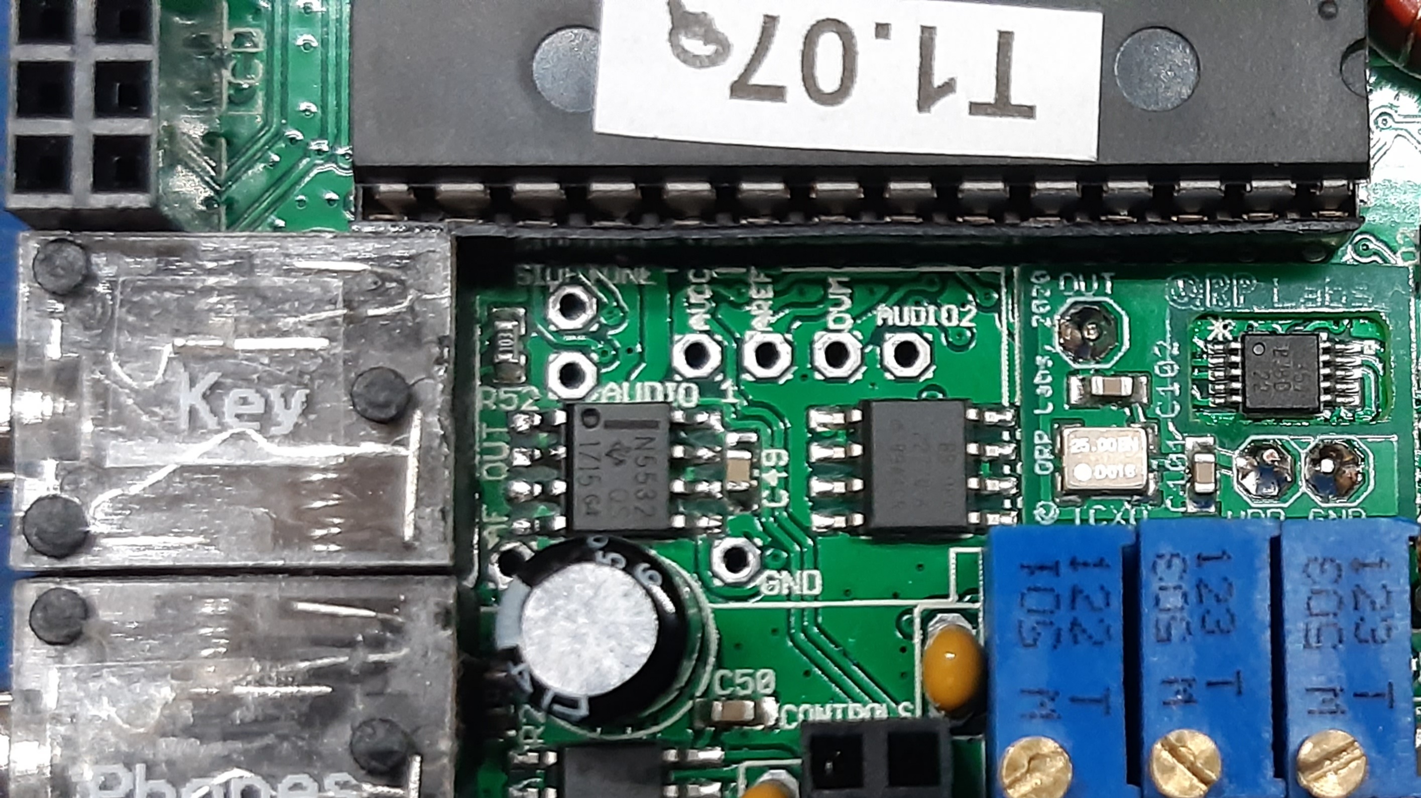
After a bit of investigation with a DVM, I suspected that op-amp IC9 was faulty on my QCX-mini. The op-amps used in the QCX-mini are OPA2277 but they seem to be very expensive. It was suggested on the QRP Labs Groups.io reflector that an NE5532 would be equally acceptable in the later stages of the receiver chain. By chance I happen to have some NE5532 chips.
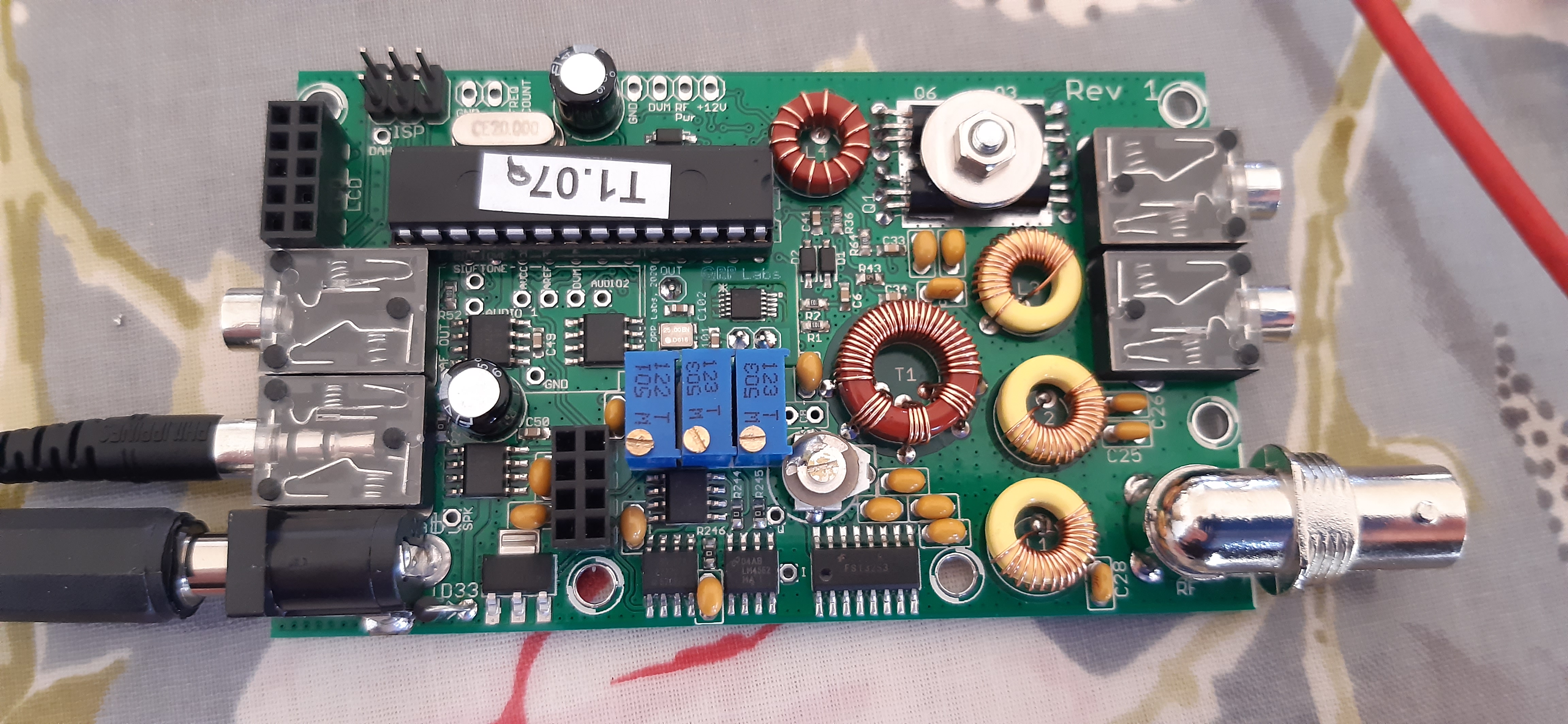
Today I swapped out IC9 and my radio is now working fine. I’m seeing 4.6 watts output on 30m from a 12v supply (idiot diode in circuit), so I’m happy with that.
I can’t wait to try this rig on air, it really is a clever packaging design.
Colin
Your video was really helpful Hans and following your advice I had a good twiddle of my toroids today. I only measured the DC voltage at the dummy load but could get almost 17v on both the 20m QCX+ and 30m Mini. Both were showing under 14v before the twiddling. Assuming my measurements are accurate this suggests the power is over 5W.
I was surprised how critical the adjustments were, just a small movement of the windings made a noticeable difference to output. I might add a few blobs of glue to keep them in place.
I guess in the real world an improvement from say 4W to 5W may not mean much but it is nice knowing the sets are running sweetly.
I’m still working on the bench clutter standards shown in your video - you are far ahead of me in that discipline.
Hi Colin,
I have a dead OP2277 in mine as well, in my case it is IC8, where the audio stops and the voltages are incorrect. Hoping to replace it next week with an NE5534. It is a very nice mechanical package.
Cheers,
Glenn VK3YY.
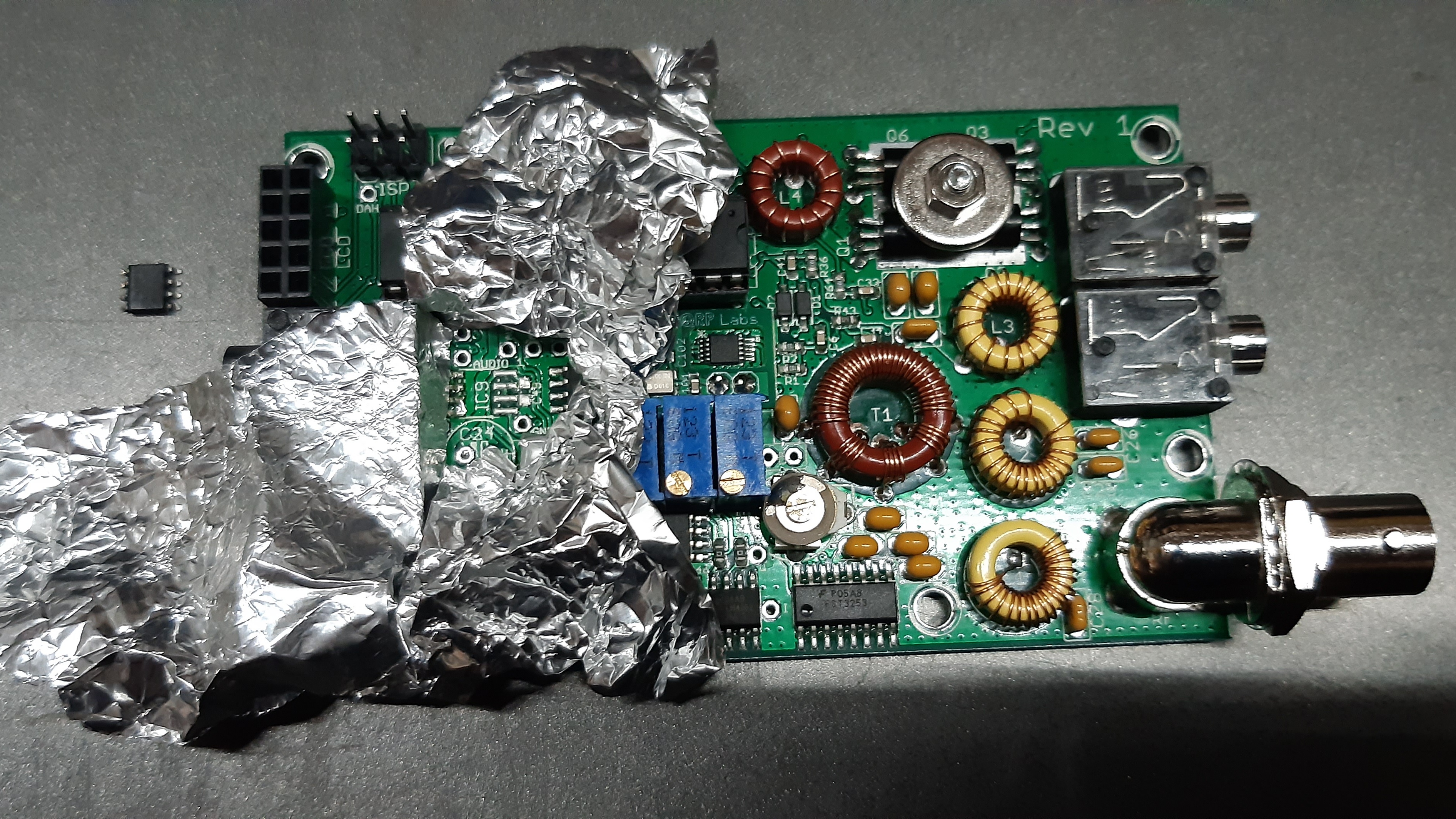
Nice work Colin. The foil is a good idea; presumably to prevent unwanted heating of nearby components? Did you use hot air?
73 Matt
Unfortunately IC9 is very close to the microprocessor socket and the key jack. I could have got in with an iron but only just and the risk of touching the plastic of the surrounding parts was high.
The foil was just belt and braces to try to prevent any aesthetic damage to the plastic parts. I could have removed the key jack but that would have been a lot of work.
I removed the electrolytic capacitor and the surface mount cap (C49) before I tackled the op-amp, again to to make things easier.
I was criticised on Twitter for my use of foil and hot air, apparently I went overboard. In my defence I would say that the PCB pads and traces are necessarily small and thin and it would be easy to lift them. I probably could have taken the chip off with just an iron and some solder, but I have a hot air machine, so I decided to take the chip off as gently as possible. I’m not in a factory production environment so it does not matter how long it takes to replace a chip. The chip came off nicely and with little effort.
My method and fix worked 100%, so that’s all that matters. Today I’m hoping to find time to make up a cable to connect the GPS to the QCX-mini to calibrate the reference oscillators.
73, Colin
Neat! What make is your hot air tool please Colin? My hot air gun is only suitable for bulk dis-assembly!