QCX Mini Part 2

Good day Andrew and others,
Make sure the “extra LPF” has both ends 50Ω of impedance, by terminating one with a resistor and VNAing or AAing the other end.
WA0ITP has a good spreadsheet, but it was cut for 12Ω.
You can trick it by changing “Desired Output PWR = 1” and playing with “Power Supply Voltage = 13.8 +/-“ to get “Load resistance = 50Ω”
I’m playing with all values to get my best LPF response and high cut off frequency with a trimmer cap for my 20W class E project.
Edit: http://www.wa0itp.com/class%20e%20design.html
Cheers, Pascal

1 Like

Feelings/ what I know.

Steve KD1JV’s MTR PA filter uses an input z of 10 ohms and output of 50 ohms. The filter not only cleans up the TX signal but also provides an impedance transformation.

The G-QRP / W3NQN low pass filters (as used in QCX etc) have a low cut off, this means they’re lossy at frequency of interest. This is with ideal values, as designed. For my projects I always use the QRPme Topper filters, they work very well and are very repeatable. I tried a QRPme filter with my QCX and whilst I got more power output than with the stock filter, I didn’t see my expected 5w.

Feeling -
The method that Hans uses for tuning the QCX (and was successful for me) starts with using the inductances at max value (turns squeezed together), by spreading the turns, it allows you to find the sweet spot for most power output. Also by means of this process, you are finding a better match for the PA impedance, so I very much doubt the QCX filter is at 50 ohms at either end. I believe that adjusting the LPF for max output also decreases the input impedance. Removing turns from the first inductor, as has been done by many QCX owners probably increases this effect and thus increases power output.

Measuring the filter physically I suspect will be hard, as I guess it’s hard to know what the input impedance is.

Using a KD1JV MTR filter on a QCX (10z in and 50z out) results in dependable power output every time. I received a TinySA at Christmas. Some resistors arrived a few days ago so I intend to build an attenuator pad and I’m going to measure my MTRs and QCXs.

73, Colin

@VK1DA (and @VK2IHL)
Andrew, I think you missed my earlier post about an extra LPF (two posts above yours).
I tried exactly that, it was a 50 Ohm in & out LPF with two connectors (only not in a box ;-), but it reduces the output power quite a bit, and you can’t leave it plugged in if you want to work on the high band. So not very practical.

The “parallel” circuit is not a LPF, but a notching series LC, resonant on the second harmonic of the low band, in my case 28 MHz.
(In Dutch we call that a “zuigkring” or suction circuit, but I don’t think that is a good translation).

In theory, that is an “all pass filter” for anything different from 28 MHz, but the capacitance at 14 and 18 MHz have of course some influence.
Measuring this with only the nanoVNA, I got a loss of 0.11 dB at 14 MHz, and 0.28 dB at 18 MHz, so I expected lower power on both bands.

[Note: The rising SWR was only for the T-piece with the LC series circuit, compared to no LC circuit on the T-piece (see nanoVNA setup in my previous post)]

So I was surprised that with the QCX attached, the whole setup resulted in MORE power on 14 MHz!
One idea is that the extra capacitance shifts the curve of the QCX LPF to a point where the 14 MHz is less attenuated ?
A typical LPF has more attenuation far below the cutoff frequency, than just before it (depending on filter type of course).

I hope you get your kit soon Andrew, this Mini is so much fun to build and use.
And if interested, you can do some of my experiments and tell us what you find … but all on your own risk , hi.

(Like Colin @M1BUU says)
Hans has pointed out that the output impedance at the BS170’s is NOT 50 Ohm, and that is why it needs some adjusting with L4 (the class-E circuit) and L3 (the TX side of the LPF). But I guess that the output (L1 side) is more or less 50 Ohm, since we tune for maximum power into a 50 Ohm load.

But I disagree with Colin that it’s not useful to measure the filter at 50 Ohm in & out. See the build report on my blog. I did measure and adjust the filter at 50 Ohm, and had 4.5W from the start, and needed just a little tuning to bring it to 5.6W. Saved me a lot of tuning and searching.

For those that don’t know this, here still some other idea.
Many use the typical LPF’s from GQRP Club, by W3NQN (like Hans does), but there are also the improved filters by W3NQN, specifically made for 2nd harmonic suppression.
https://www.arrl.org/files/file/Technology/tis/info/pdf/9902044.pdf
I haven’t tried those yet, some day I will …

Now, all my experiments are just for fun, I don’t want to change anything inside the QCX itself.
Those “mint in box” Mini’s will be a collectors’ item some day :wink:
73,
Luc ON7DQ

1 Like

Rrr I must have read that earlier and should have reviewed it. My mistake. A very interesting topic.
Thanks for posting the results of your experiments.
73 Andrew VK1DA/VK2UH

Hi Colin,
Steve and Hans class E PAs are 2 different topo.
Steve uses an “infinite DC supply ferrrite core 43 type). His LPF is involved in a double role as load network and harmonics elimination.

Hans, in contrast, uses a “finite DC supply” (powder iron - 6 material”), to fulfill the charging and discharging of energy, the circuit has to use his LPF’s LC, that explained why, by altering the L3 inductor, more or less power will be produced dramatically.

I managed to design and have a breakthrough to maintain my EPA at 50Ω output.
You may follow it from here:
https://vk2ihl.wordpress.com/2020/12/24/vk2ihl-20w-all-mode-sdr-part-two/

Cheers, Pascal

My 2¢ comment was addressed to my friend Andrew, as I mentioned when changing capacitor values with SWR monitoring, I am capable of maintaining 50Ω for my LPF.

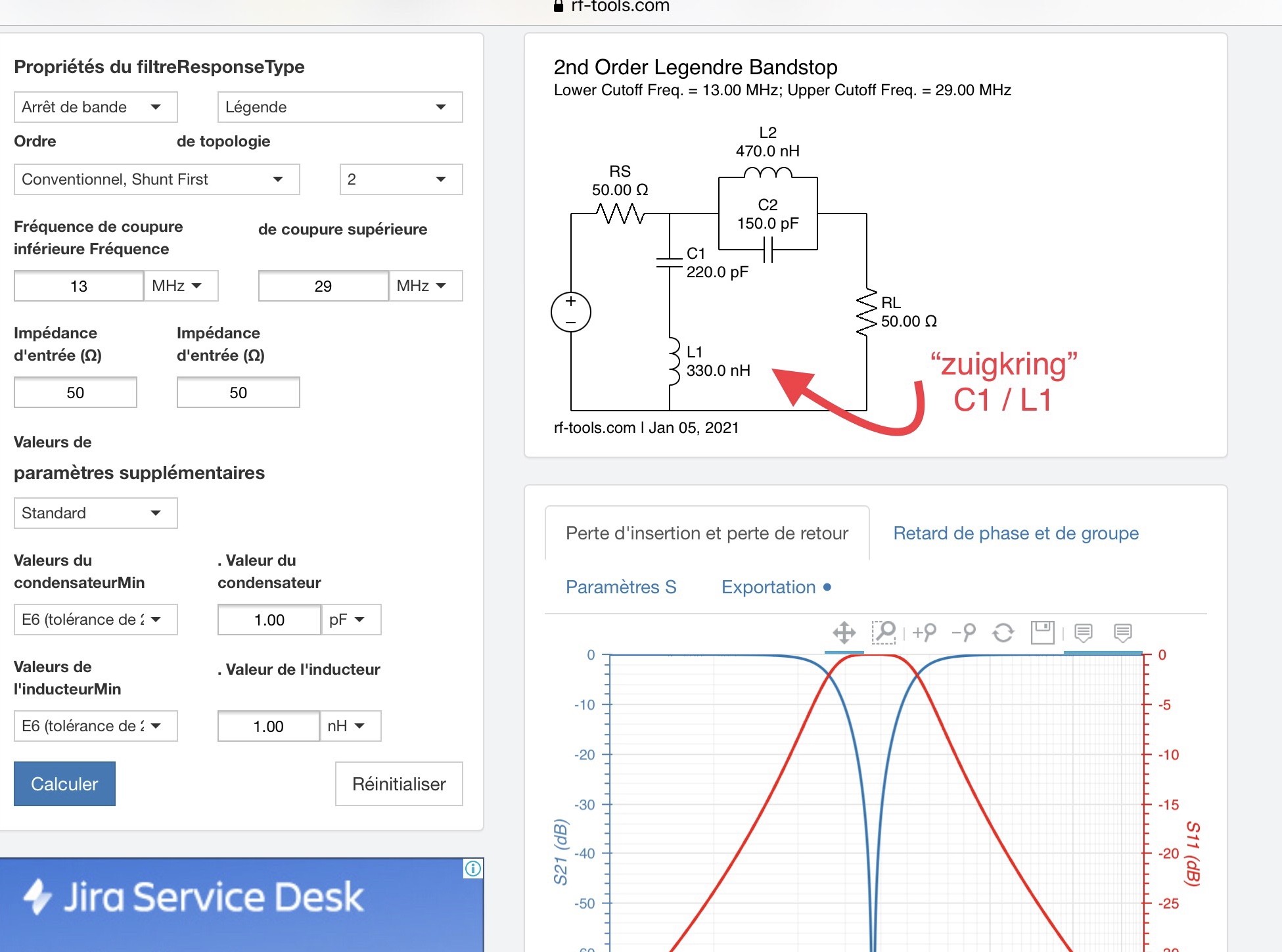
I fully understood your “shunt circuit”.

Cheers, Pascal.

1 Like

New post on my blog, about the LPF and series circuit, with full details and measurements.

And hahaha, this is the first time the Reflector says I should shut up!
I got this message …
“This topic is clearly important to you – you’ve posted more than 26% of the replies here. It could be even better if you gave other people space to share their points of view, too. Can you invite them over?”

Sorry … :flushed:
73 Luc ON7DQ

4 Likes

It’s annoying when it says that… ignore it as you are posted interesting information.

It has been interesting and helpful to follow this thread. I got my 20 meter kit built up late last week.
With an Elecraft dummy load the power out was only 1.5 watts or so. I mistakenly took two turns off L2 which lowered the power. Trimming L3 got me up to about 3 watts. Compressing the turns to half the toroid on L2 produced 5.3 watts. The supply voltage was set to 12 V. Next I tried my Bioenno LiFePo battery. The measured power was 7.3 watts! No more QRP, hi.
A Siglent SSA 3021X was available so I thought I’d try measure the harmonic filtering. But I don’t have any suitable attenuators. Instead I laid the dummy load board on a pick up coil plugged into the SA.
On 14.060 the signal read -23.9 dBm. On 28.120 the reading was -39 dBm. On 42.180, -50.5 dBm.
Having never done this before I don’t know if there is something wrong with my measurement method.
Are these values meaningful?
Is there some calculation involved to find the actual attenuation value?
Does the higher power output coincide with higher harmonic suppression?

I may try opening the turns on L2 to decrease the power output to 5 watts or less.

I have an Elecraft XG1 which I used to check the receiver. The difference between 1 uV and 50 uV on the S meter set for 10 segments was gratifying, no indication at 1 uV and full segments at 50 uV.
Because I have no antenna HOA restrictions the radio has yet to hear real signals.

Hopefully, I can try my QCX mini out with an antenna soon.
73,
David N6AN

1 Like

Hi David @N6AN

I don’t think your measurement is valid, the pickup coil will have a different coupling at different frequencies, so it’s only an indication …

Is your dummyload the DL-1 ?
You can easily modify it into a 40 dB attenuator (or other value), more or less like this one I once made (but this is not the one I used in my measurements).

The load is a 20W 50 Ohm resistor in a TO-220 housing
The input is the lower BNC.
Then to the right, in series, is 1500 Ohm + 2 x 4700 Ohm in parallel, so a total series resistance of 3850 Ohm.
Finally in parallel another 51.1 Ohm resistor.
The SMD resistors were from my junkbox. Other resistors will limit the frequency range, but should be OK for HF work.

It’s not perfectly 50 Ohm from both sides, but good enough, and surely better than that pickup coil.
Attenuation values can easily be calibrated with your Spectrum Analyzer, using the Tracking Generator (I use the same model SA here).

For a better flatness, I added a piece of PC board on the top, same size as the base board, connected to ground at the left side with a stiff wire, which holds the “screen” just above the BNC connectors.

I get -40.07 dB at 30 MHz, -39.46 dB at 145 MHz, so still very good, only at 435 MHz attenuation gets worse with -36.40 dB.

EDIT : Another option is to build a Power Sampler like this one:

Google for “Power Sampler”, and you’ll find several other similar designs.

73,
Luc - ON7DQ

3 Likes

Thank you, Luc.

That makes sense. I need to get a broadband flat response pickup coil, hi!
My parts stock is very limited. Perhaps I can scrounge what’s needed for a low wattage attenuator.
Kudos on your homemade unit.

I widened the turns on L2 to drop the power to around 5 watts with a 13.2 volt supply.

73,
David N6AN

DL9SCO has published a couple of very nice videos on youtube:

  1. QCX Mini - Assembly: QCX Mini - Assembly - YouTube
  2. QCX Mini - Smoke test and alignment: QCX Mini - Smoke test and alignment - YouTube
  3. QCX Mini - Installation in the optional QCX Mini enclosure: QCX Mini - Installation in the optional QCX Mini enclosure - YouTube

Have fun!
73, Roman

3 Likes

Yesterday, I made a small Battery Box, matching my QCX Mini
(for ON & PA hams, I found those small “Radio & TV” theme boxes in the WIBRA shop).
It has almost the same size and thickness as the Mini, and weighs 180 gram … “batteries included” as they say.

Inside are 3 Li-Ion cells (2200 mAh) for 12V output, the box has on ON/OFF switch, to reduce the number of times inserting or extracting the DC plug at the QCX Mini.
And @G0UPL, it even has its own FUSE , hi.

The insides of the box are covered with a thick plastic film (ex laptop motherboard protection), and all is fixed with generous amounts of hot glue.

I charge it by connecting the plug to a 12.6V stabilized & current protected power supply, so no balanced charger … (note: for the picture, it was not fully charged yet)
I know it’s against all logic, but my experience is that cells of the same batch charge reasonably equal. And if I ruin the cells, I have many more where those came from, they are easily replaced. Or if I think I need it, I can connect a balancing connector.
73,
Luc ON7DQ

5 Likes

Due to it being perishing cold on the summits today, I decided to have a poke round in the QCX Mini. It had developed an intermittent problem with the volume, depending on how you touched the knob. After removing the QCX Mini from the case and turning it on, I found the problem had spread to the VFO. I noticed a dry joint at the header pins of the VFO controller. After remelting and adding a bit more solder, the problem was completely sorted. I had another play with the toroids and got TX up to 5W at 12V, and over 8W at 15V. I’ll call it good at that. As I was putting everything back together, I noted how the knobs can work loose, slide down the shaft and contact with the enclosure. This means that the click function on the VFO no longer works. I was thinking about what I could shove down the hole to create more clearance, and suddenly realised that the holes are about the same size as a paper punch:

I took an old ski pass and punched out about 4 discs per knob and shoved them in with a hex key. Voila, the knobs always have the right clearance, even if the grub screw works loose:

I got some new speakers recently and they came with small plugs in the banana sockets that presumably keep the dust out:

With a little trimming they fitted perfectly in the CAT & PTT sockets; and looked rather smart too:

Just minor tweaks really I suppose. My QCX Mini is now completely finished and operational. It will be coming with me on most of my motorbike activations when I put the bike back on the road at the end of March.

       73 de OE6FEG
            Matt
9 Likes

Great work Matt.

I unexpectedly acquired a dead QCX-mini 40 this week. I have spent a few hours with a solder sucker removing all the excess solder from the through hole components. I re-wound the toroids and bridged across the lifted tracks on T1 (reason for scrapping and entering my possession).

I fired up the rig this evening and I’m seeing 4 watts output at 12v without even adjusting the toroids. Much to my surprise the RX alignment went absolutely fine.

I swapped out the 5v regulator for a branded one.

Good progress for today, next I have to fit the case and do the GPS frequency calibration.

73, Colin

6 Likes

Neat winding on the toroids. :slight_smile: I struggled to keep count of the turns on T1 and ended up taking a photograph, printing it out then counting them on the image. :slight_smile:

2 Likes

Yes, that’s a good technique!
I wound my toroids in the dark yesterday evening whilst XYL was watching telly. I took a photo of a part wound T1 to count the turns.

8 Likes

T1 looks like it was “machine wound”. Absolutely beautiful job.
A++

3 Likes

A piece of tapered dowel (or paintbrush) in a vice makes life a hell of a lot easier:

       73 Matt
9 Likes

For the 3D printer folks, there is this toroid winder aid