Portable 7-Band EFHW Antenna

Thanks Stephan for your great write-up, I’ve almost finished building one and first tests in my garden are looking good.

IMG_0985

I 3D printed a box for the transformer with a selection of mounting points that will give me a little flexibility in how I support it:

This is the first version in PLA, I need to re-print it in a more stable material (probably PETG will be OK for my use). Hence the ty-wrap to hold the lid on at the moment :slight_smile:

I also decided to go for a pluggable coil for now, in case I needed to adjust it (and also because when I searched my garage I couldn’t find the bit of 20mm conduit I thought I had!). I used the 2mm gold plated plug and sockets. So for now I can use the antenna as either a standard 40m EFHW or open the link for 17m. I’ll build the coil this week.

IMG_0987

Apart from 40m, all the bands I can currently use it on are showing low VSWR, 40m is up to 2:1 at the top end of the band (but I think that matches one of your graphs), but my garden has quite a lot of trees so I can’t get it into as open an area as I would wish.

Thanks again for the nice info, and look forward to working with it!

73, Jonathan

6 Likes

Very good Job, when i have further Questions i will contact you directly.

Thank

Michael DC8YZ

1 Like

My attempt at the antenna. Pretty much same SWR sweep as NY4G when setup in an inverted V.
I should have run the small section of cord under the heat shrink instead of taping it after the fact.

Malen
VE6VID

3 Likes

Hi Jonathan,

Thanks for sharing and showing us your solution!
Also thanks to @VE6VID for his solution.

Your 3D-printed case looks very well engineered. And to use a pluggable coil is also an interesting alternative.

Concerning the high SWR on the 40-meter band:
I assume you measured it with an analyzer at the coupler feed point and added some piece of wire as “counterpoise” (e.g. 2m long).
When looking at Figure 31 (page 39) in the document, one can see that one field measurement shows also an SWR of around 2 on the 40-meter band. Therefore, your measurement from one location looks OK to me.

These different SWR values depend mainly on the environment and it is hard to predict, but can only be measured. For example, at the beginning of my experiments, I thought that on a flat field without trees or other obstacles I’ll see better values than in a dense forrest, but in reality, this is not always the case. There are so many factors involved.

73 Stephan

2 Likes

Thanks Stephan,

I measured the SWR at the rig with a 7m RG58 feed (I’ll probably switch to a shorter RG174 but at the moment I can carry just this one feed to use use with another antenna as well). For now I’m going to run it with your dimensions and see how it matches in a few different locations before I worry about any fine tuning, from my early tests I don’t think it’s far off which is testament to your nice instructions.

I will pop the STL files for the 3D printed box on Thingiverse soon in case anyone else can make use of them.

73, Jonathan

2 Likes

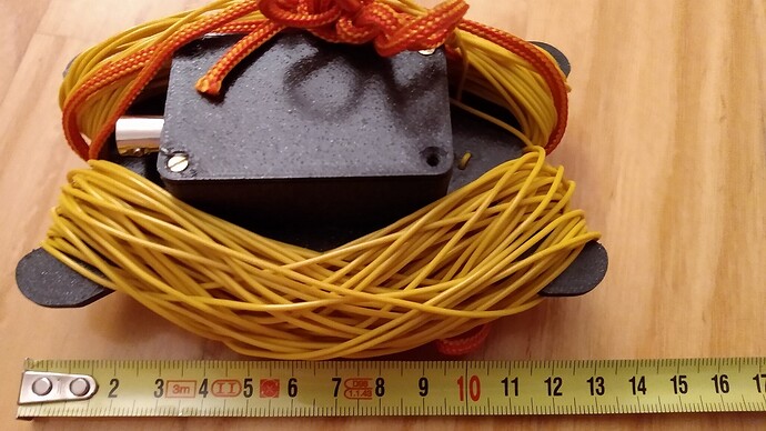
Just in case someone is looking for 3D design here my box plus winder design already on thingiverse

6 Likes

Hi All,

Following references to several articles on type of winding 49:1 transformer, and this excellent thread I decided to do some actual comparisons to have better handle how much more efficient actually is.

I used FT140-43 core as this is what I use for my portable operation. I wound Classic 21:3 style with twisted 3 turns and crossover after 7 turn. Next on the list autotransformer with a tap on 3rd turn. Finally I done two versions of KN5L style windings with 21:3 and 28:4 turns.

Here is what I got.

I used nanoVNA for inline losses measurement and converted it into percentages for efficiency which is easier to see the difference.

I hope some of you will find it useful in selecting method of build of your next transformer.

73 Marek

3 Likes

Its good to know that the KN5L method produces good results. Everytime I try to wind it I make an error someplace. Wire is cheap, so I will try another time.

Malen
VE6VID

3 Likes

Hi Marek,

Thanks for publishing your results, very interesting!

What would be also interesting, if you would wind with this KN5L style, but using a core with another geometry, or stacking two of the FT140-43. Maybe the Fair-Rite 2643625002 is a bit small for this winding technique, but worth a try. I wanted to try it myself, but you know…

What puzzles me a bit is the low efficiency of your measurements on the 10-meter band for all of them. I guess that the winding capacitance is the biggest problem at this high frequency.

When looking at my calculations I did with Owen Duffys calculator using the #2643625002 core with a turn ratio of 24:3, one should never see less than 90% efficiency for your measured bands. I know, calculation is one thing, measuring another.

I had some email conversation with Gary Rondeau after he published this interesting article:

Several parts in his article don’t apply when doing QRP (like the voltage breakdown and heat dissipation) but it’s a very inspiring read.

To me the most interesting aspect of this KN5L winding technique would be to use a EFHW on the 6-meter band, but I don’t know if this really feasible, even after seeing his low measured losses below 50MHz.

73 Stephan

2 Likes

Marek,

I am curious as to what SWR distributions you were able to get with your different windings. I find that sometimes a compromise may need to be made between SWR and efficiency. In my experience, I have found the 24:3 winding ratio to give a good compromise. I also found that the #2643625002 core gives efficiencies higher than 95% in the low bands trending to about 90% on 10m with this 24:3 winding ratio. .I found that stacking two FT140-43 cores to be more efficient than a single core but winding ratios greater than 16:2 tend to give a worse impedance match across the bands.

Ariel NY4G

3 Likes

Hi Stephan @HB9EAJ ,

Not sure about poor 10m band efficiency, maybe this is mechanical due to the way I make them, or poor quality of capacitor or something else.

I will try different core FT140-43 or maybe two cores stacked up. I was also thinking about changing number of turns which overlay first 4+2 turns. At present there are four. I need to read KN5L article again and study his photos more closely. I will also try to make even shorter connections to the socket.

But first if weather is nice this weekend I will connect this transformer to my shorten EFHW8010 and see how it looks with actual wire.

Thanks for a new link, I will study it closely.

Ariel @NY4G my experience of balancing bandwidth and efficiency is the same. I tend to go for efficiency first. I will connect transformers to nanoVNA and fiddle with wires in order to get best readout. Then I check bandwidth and decide if compromise is needed.

Here is SWR reading on transformer in question (KN4L style winding) using 2500ohm resistor.

I used FT140-43 as opposed to #2643625002 core mainly due to the power handling capacity. Appart from SOTA from time to time I also do POTA and WCA and I run then 50W from IC7000. I wanted to have one set of gear for all portable activities. Maybe I will need to revisit this approach.

Thanks for comments guys. I will keep you posted if I improve things further.

73 Marek

2 Likes

Marek

I notice you used a resistor to simulate the antenna. The impedance of the antenna for the different bands do not stay constant and the SWR mismatch is better on some bands and worse for others. The compromise is in prioritizing which bands have to have the best SWR match on the real antenna. In my case I prioritize also on efficiency first but the SWR on 40m and 20m have to be acceptable. The other piece of the compromise is the SWR bandwidth. Fewer primary turns makes for a wider bandwidth in general and specially on 40m at the expense of efficiency. I do agree with you that the FT140-43 is a good all around core for its power handling capability and I found that out also to be good for both SOTA QRP and POTA running 50-60W and the occasional 100W. I do think that you have found a “sweet spot” compromise suitable for all your portable activities. I have similar results comparing efficiencies similar to what you plotted - Cool Things That Can Be Done With a NanoVNA - YouTube time stamp 25:34 comparing the #2643625002 core transformer versus the transformer supplied by LNR on their trail friendly 40-20-20. Thanks for sharing your results.

Ariel NY4G

2 Likes

Ariel @NY4G,

I finally watched your video and must admit that I am not sure if you can use your method for efficiency measurement of the transformer. I might be wrong by you measured return losses.

I am under impression that you need two identical transformers connected back to back and then by measuring S21 you have inline losses of two transformers. Dividing by two you get result for one. That what I have done.

After that I took one transformer as a reference point and measured different 49:1 versions. This time from the measurements I subtracted known losses of reference transformer, and I got losses for measured one. I hope you can follow.

73 Marek

2 Likes

Marek @SP9TKW

I tried both the back to back method and the resistor method. There appears to be an interaction effect when I have the transformers back to back. Owen Duffy recommends the resistor method and that seems to have more consistent results. It is somewhat sensitive to layout on the the S21 sweep and I try to keep my layout as consistent as possible. The efficiency appears to be related to core geometry and the number of primary turns. At the end, the measurements are more relative tan absolute since the resistor is only a simulated antenna. I used the Owen Duffy method in detail as described in his blog.

Ariel NY4G

3 Likes

Hi all,

First, many thanks for all your feedback and ideas that are very interesting and valuable to the community! Lots of things to experiment with.

In case you’re interested how quickly one can setup the EFHW antenna in inverted-L configuration, then please have a look at my latest video:

The main reason why the setup is so quick, it’s because I don’t use any guying, but the fishing pole support from Decathlon (links can be found in the document).

Further, I recorded four contacts using the TX-500 from Lab599 on the 40-meter band with @G0FEX, @F4WBN, @EA2DT and @ON4CB.

73 Stephan

10 Likes

Hi Stephan, thanks for your great video. Very enlightening.

Cheers Geoff vk3sq

1 Like

Thanks Stephan for sharing, indeed very informative.

I noticed that you setup antenna with end pointing towards North-West? Was it on purpose or just convenience?

73 Marek

1 Like

Hi Marek,

Thanks for your question that I sometimes ask myself, especially when I have different directions to choose from.

When you look at page 29ff in my document, thanks to the inverted-L configuration, the radiation pattern on 40m and below is pretty uniform. But on 20m (probably also on 30m, but I didn’t check the model for this band) and above you’ll get some directivity.

Usually, I look for the most easy setup (comfy place to sit, most open space, no tangling branches, etc.).
This is also kind of fair to the chasers on the higher bands, because over time, all directions are more or less equally “used”.

But of course, participating in the upcoming Trans-Atlantic S2S event, apart of the summit, I will definitely take the direction of the horizontal radiator wire into account.

73 Stephan

2 Likes

Hi Stephan,
Without having modelled and just following my instinct, I setup my inverted L for the Trans-Atlantic S2S event considering that a perpendicular to the plane determined by the inverted L is the one with the maximum radiation, but I’d like someone to simulate it and confirm whether my instinct is right or wrong.
Also, when I setup my antenna wire as a sloper, I always try to do it in a way that the wire slopes towards the direction I want to prioritize, i.e. towards the North-East for Europe and towards the North-West for NorthAmerica.
But, again, this is something I’ve never confirmed with a simulation, only with my own results and experience during my activations.
I’d like to see what computer simulators say about this.
73,

Guru

1 Like

The “instinct” may be good enough in the case of half-wave radiators. With shorter and longer antenna radiators than 1/2 lambda it is usually a bit more demanding.

For this reason, a user compass was added to my document “All-band antenna for the KX2/KXAT2”.

1 Like