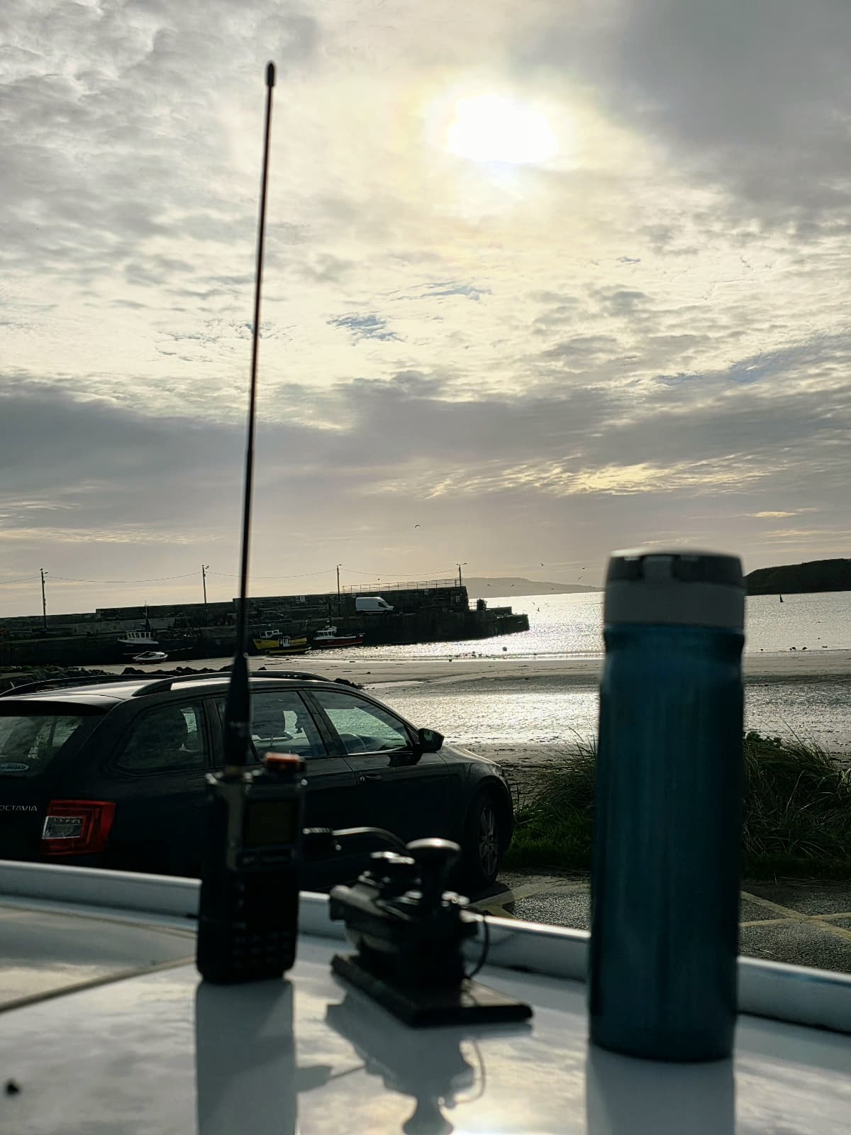
Tried now to hold the key in one hand and work the other ![]() Seems to be okay’ish, but no more than 15 wpm though! A pain in a pile up … as I will have on 2m for sure
Seems to be okay’ish, but no more than 15 wpm though! A pain in a pile up … as I will have on 2m for sure ![]()
Another idea is to get my USB Plantronics headset converted and try to VOX it for FM/SSB semi hands free.
The pile up will be so fast and frenetic that your hand will blur and flames and smoke will begin to emit from the key. ![]()

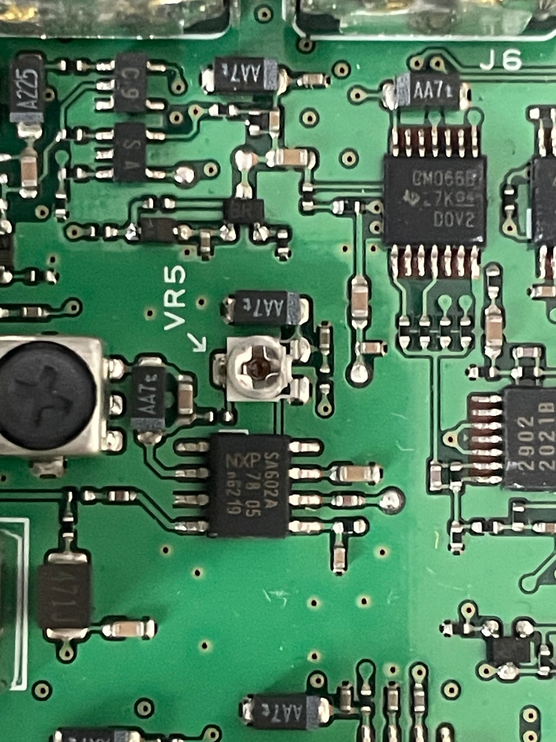
While making and testing a headset, I’ve noticed a nasty misalignment in the FT-857. Transmitting in SSB had a noticeable carrier present on a background. A quick browsing on the net pointed to a carrier balancing variable resistor VR5 on the main board (as easy as to take a top cover). That worked 100% I’ll leave the picture of the adjusting element here for reference in case anyone experience a similar issue.
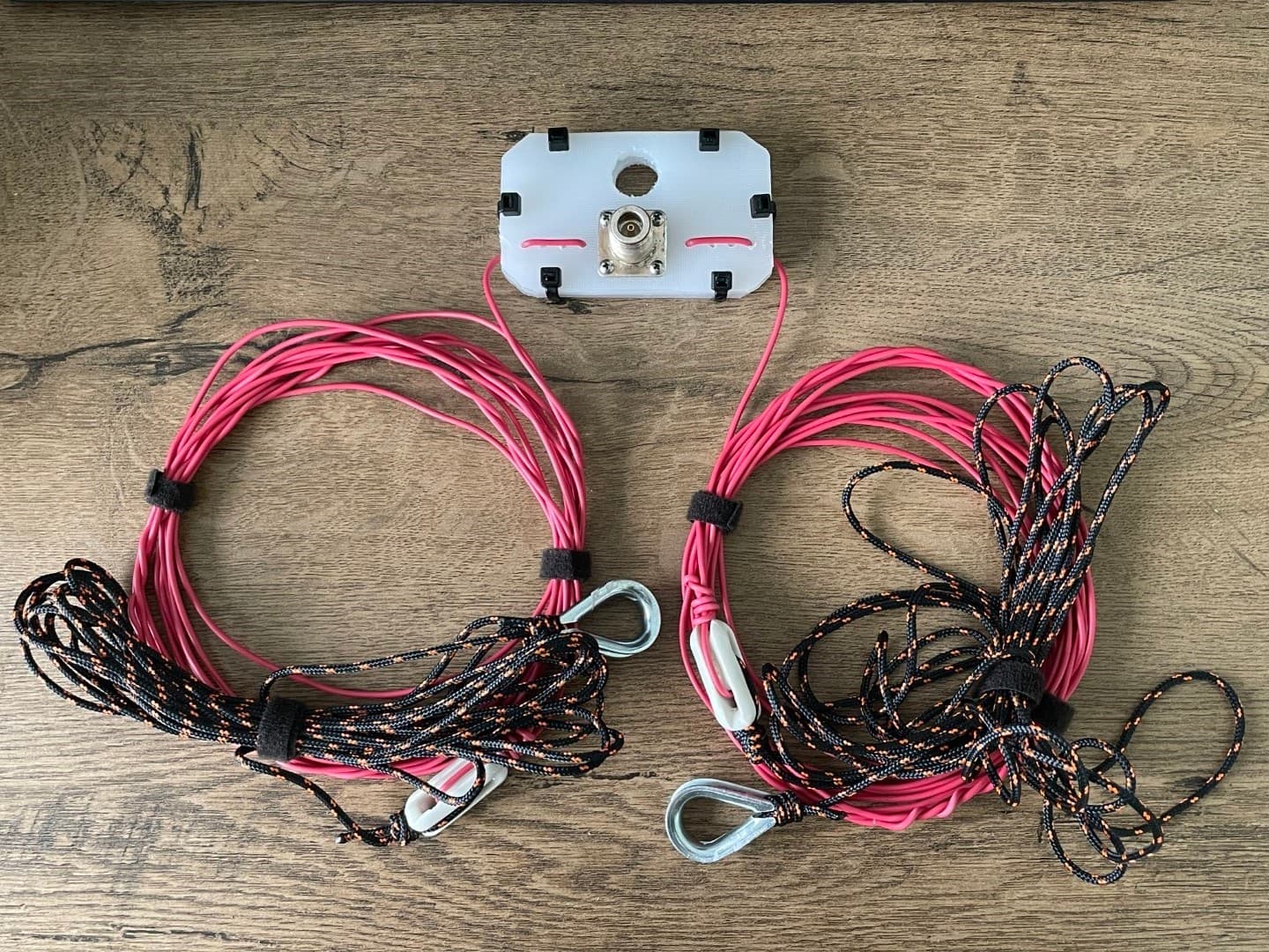
So I’ve made my first portable dipole! Cut for 20m band, with extra 50cm left on each side for final trimming for now. The dipole is going to have a low feed point of 3m (a collapsible aluminium mast I have). I will use a fairly non-standard 93 Ohm coax feeder. Tesco cutting board nylon used for the base and ancient Soviet ceramic insulators at the ends. Now waiting for the next reasonably ok’ish weather slot to try that out! Curious to see how that works in the field ![]()

That should be fine if you use a tuner, or cut it to an electrical half wavelength (or multiple thereof). For RG-62 with a velocity factor of 0.67, that would be a length of 3.55m. (Stick a 50 ohm load on the end and adjust the length for lowest SWR.) I’m using this approach with 75 ohm coax and it works well, although since I’m using it on 40m, the coax is rather longer than I would normally carry.
If you leave the extra 50cm (or a bit more) hanging down on the ends after wrapping the wire around the insulator, you can fold it back and/or trim it off without needing to retie the insulator with each adjustment.
You’re off to a good start! When you have it working and are ready to reduce weight, here are some other possibilities:
Using synthetic ropes to tie off the ends means you already have a few metres of insulator - no need for the additional few cm of ceramic at the ends, even at full power from the FT-857.
The center insulator can be made smaller: a single layer of plastic with the wires tied to it will provide strain relief.
0.4mm (AWG #26 or BWG #27) stranded, insulated wire is quite sufficient for your maximum power, and saves weight. The insulation actually contributes to the wire strength.
Thanks Dale! That is some valuable post indeed and I definitely try some of the techniques. The last time I’ve built a dipole was some thirty years ago, and I’ve never built anything like that portable.
I’ve used those ceramic insulators just because I found them as a handy, ready to use mechanical joints for the ropes or wire. A sole purpose of a second layer of nylon at the base is to provide some cover from elements for the connector soldered part. I guess that is a bit of excess though.
My main concern is how dipole’s SWR changes going from one hill to another? Say I’ve adjusted the dipole on one hill, however on another hill I would need to raise or lower the ends or change an angle et cetera … As long as I have no tuner I now see it as a problem.
I’d suggest using BNC rather than SO239/PL259 connectors as they are smaller and lighter. They are also easier to connect and disconnect.
I have a Vee dipole on a 6m pole that I use for SOTA with my FT818, I find it quite forgiving when pitched under differing hill conditions, but I am only running 5w. It may need a bit more caution with higher power. I have a toroid BALUN at the top where the coax meets to antenna.
The SOTAbeams website has a good calculator that I’ve used for linked dipoles.
What may change things is if the pole height changes the impedance will vary.
I’ve run my FT857 into my Vee dipole up to about 20w a couple of times and it has not objected too much.
I’m interested in your current measurements for the FT857 at different power levels, it would be good to see the current draw for SSB conditions on a few bands as well if you get around to it.
Andy
MM7MOX
You’ve already off to a good start, Alex, just by making the dipole in the first place. Get some experience using it before making changes (or building more of them… no, let’s not talk about how many I have in the garage).
The tuning will vary somewhat each time you set it up, but I just tuned my antennas up in a “typical” configuration or perhaps a bit worse than what I expected in the field, for better SWR when other performance might be somewhat degraded. I’ve rarely carried a tuner in the field, and several of my portable radios don’t even have an SWR meter to tell me how good (or bad) the match is. I just plugged it in and used it, sometimes in rather quirky situations. And usually, it worked. The one time it didn’t, I had run it along a barbed wire fence in Nova Scotia.
If you are using a 3m center pole, the biggest variation will be due to the height of the ends above ground. That’s easy to standardize when setting it up on a nice flat lawn where you can use pegs at the desired distance, but many summits aren’t that cooperative and you have to get creative. For now, if you are using the FT857, it probably reduces power to 10W or so to protect the finals if the SWR is too high. If so, reduce the drive and just run 10 watts - it won’t hurt the radio.
However, that’s a good experiment to run in controlled conditions: vary the height of the ends and the angles of the wires to each other, and see how the SWR changes and the radio responds. That’s something you can do in a back garden. (This video will give you an idea of my “backyard antenna test range”.)
When you are ready to save weight, yes, a BNC connector is lighter (although harder to clean sand out of), and an RCA audio plug even lighter still, which my first 2 QRP radios used. (It is also easier to fit on odd feedline types, and to repair in the field if stepped on.) My solution was not to have a coax connector at the antenna, making the weight on the mast even less.
I’ve used a number of different methods of waterproofing over the years, including hot melt glue and liquid electrical tape. My current favorite is a spray can of “Flex Seal”. But I never got around to protecting the RG-174 in my original kit, and the measured losses after 45 years are still pretty close to spec, in spite of several heavy downpours.
But don’t worry about making changes yet - get out and use it instead, then figure out what works best for your and your equipment. There’s no “one right way” to do it.
Another great, very informative post, Dale! Ideally, I wanted to have a selection of resonant dipoles for 40/30/20m bands, perhaps a wrong idea and a long wire would be a better option, but if 20m works ok I may try something similar for 40m and 30m too. Luckily, 857 has an SWR meter, so It should’t be too difficult to adjust a dipole on a summit or at least to control what is happening.
I am okay with some extra weigth at present so connectors doesn’t bother me, especially carrying an excess of 12kg rucksack. That could change with time though. Personally I like N type connectors, especially as Pls could be difficult to unscrew sometimes. I’ve never looked at BNCs though, perhaps worth paying attention.
I hope to have a cable and pegs ready this week, so if weather plays ball I may go uphill this Sunday, can’t wait actually to test that out.
Now I got my cable measured! It just happened I have only 7.6 meters of RG-62A/U 93 Ohm cable. According to spec its velocity factor is 0.83. After doing the math I was expecting to get the best SWR in around 16.5MHz and that exactly what happened! Having an industrial 50 Ohm load at the end, both 857 SWR meter and a standalone meter showed a perfect 1.0:1 match at 16.7MHz and acceptable 1.2:1 match in the range of 14-18Mhz
Apparently, cable cut won’t work in this case and unfortunatelly I don’t have a longer segment to get it centered for 20m band. Nevertheless, I suppose it shouldn’t matter much as long as I stick to 20-17m bands.
Perhaps it wouldn’t be a good idea to use it for 30/40 meters, need to get a 50 Ohm for that.
It was an interesting experiment though as I never looked at cable length and how it could affect things. Although I’ve only used 50/75 Ohm before.
P.S. After scratching my head about ‘do I really want to use that 93 Ohm cable’, I’ve came up with a better way around the cabling. I just use my VHF 6m 50 Ohm cable. It has N type connectors each end, but I’ll use adapters I have ready in the drawer. As an immediate bonus, I should be able to adjust the dipole moreless properly. and experiment with other bands fearlessly till I get correct cable delivered (likely after Xmas, in January)
Actually, there is a simple work around for that. In my case, I was using a 75 ohm cable for 20m and 40m (where it was a half wavelength), and wanted to add 30m as well, where it was close to 3/4 wave resonance, so would transform a 50 ohm impedance up to over 100 ohms.
The solution is to design the antenna to provide the required impedance at the feedpoint that shows up as 50 ohms at the rig end. A convenient way to do that is to use AC6LA’s TLDetails program (or other reputable feedline calculator), select RG-62A/U, specify the length and a 50 ohm impedance at the input, and let it solve for the load impedance. In this case, I get 56 + j29 ohm. So if you just cut your antenna a bit long, it should come out pretty close. Assuming it is going to be close to 50 ohms, of course…
But while you are at it, let’s consider how the impedance changes with height. Since I have EZNEC open on the same computer as TLDetails, let’s see what a 20m inverted vee at a height of 3m over poor ground (with the ends up 1m) might look like. Close - about 58 ohms. Extend it a bit to get the desired reactance… looks like a total wire length of just under 10.5m would give 64 + j27 ohms.
TL;DR: With the cable length you have, just adjust the wire length for lowest SWR, and that will account for the impedance transformation in the coax.
On other bands you may need to get more creative. In my case, on 30m I needed an antenna impedance around 115 ohms, which I achieved by lengthening the antenna to get the desired resistance, then adding series capacitors on the wire where it connects to the feedpoint to tune out the added reactance.
Cheers Dale, I’ll stick with my VHF 50 Ohm cable for now, at least that gives me a uniform feeder for all bands so I can play around actual dipoles. But this is a good lesson to learn! I would need to have a look at the SW, looks like a great toolset.
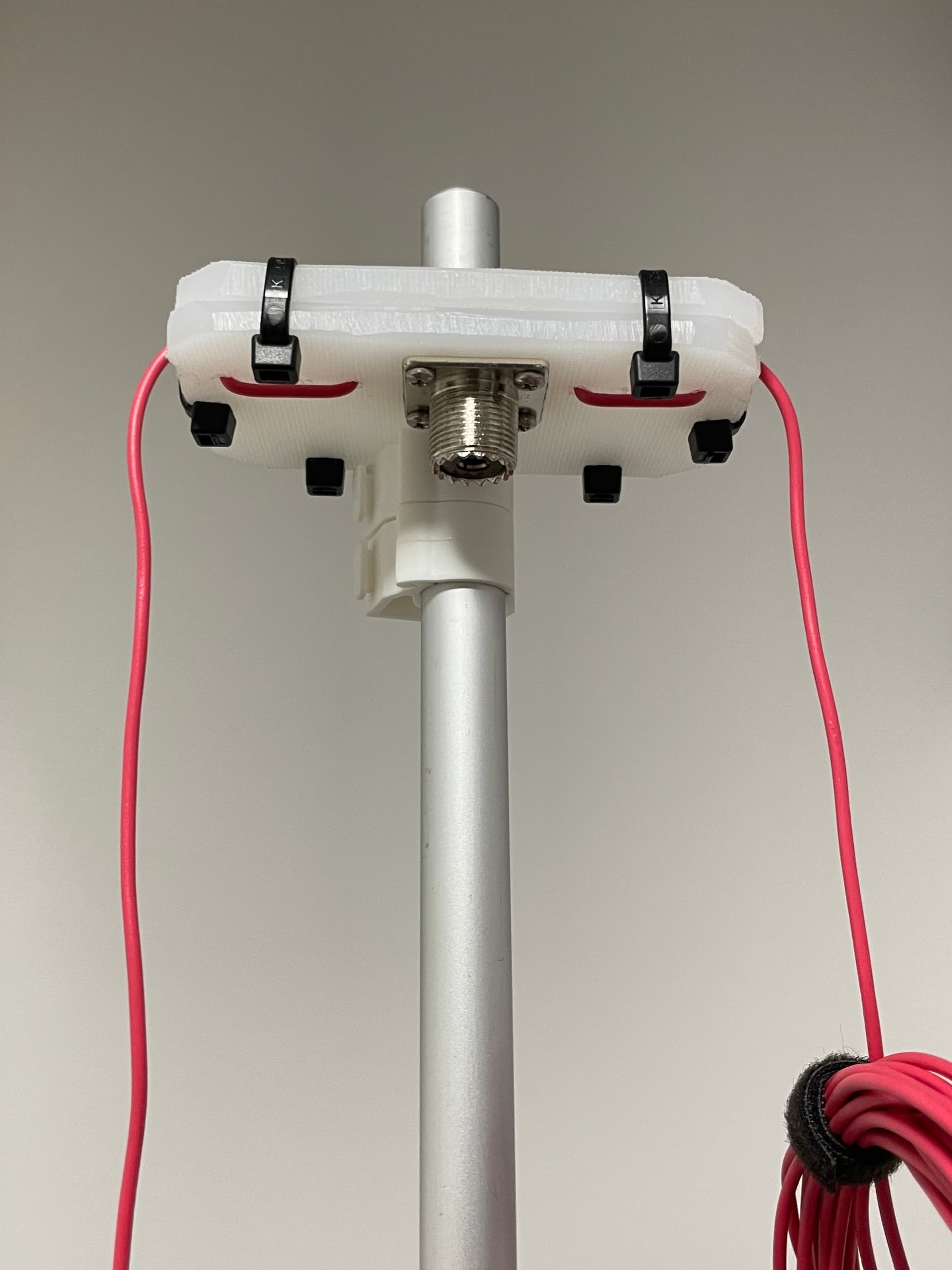
After my three 20m activations I’ve re-worked the dipole a bit. 3m wire guys replaced with 4.5m rope guys and I’ve replaced a PL connector with my beloved N-type.
Then I’ve made an extension to the mast and now it is full 3m in height. Still low, but I have what I have at the moment. I still have to stick to my tripod for now, as it is too handy for V/UHF work.
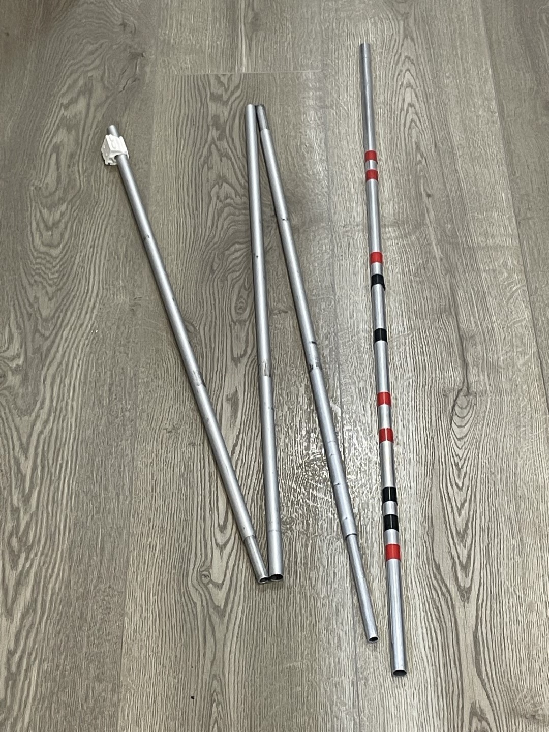
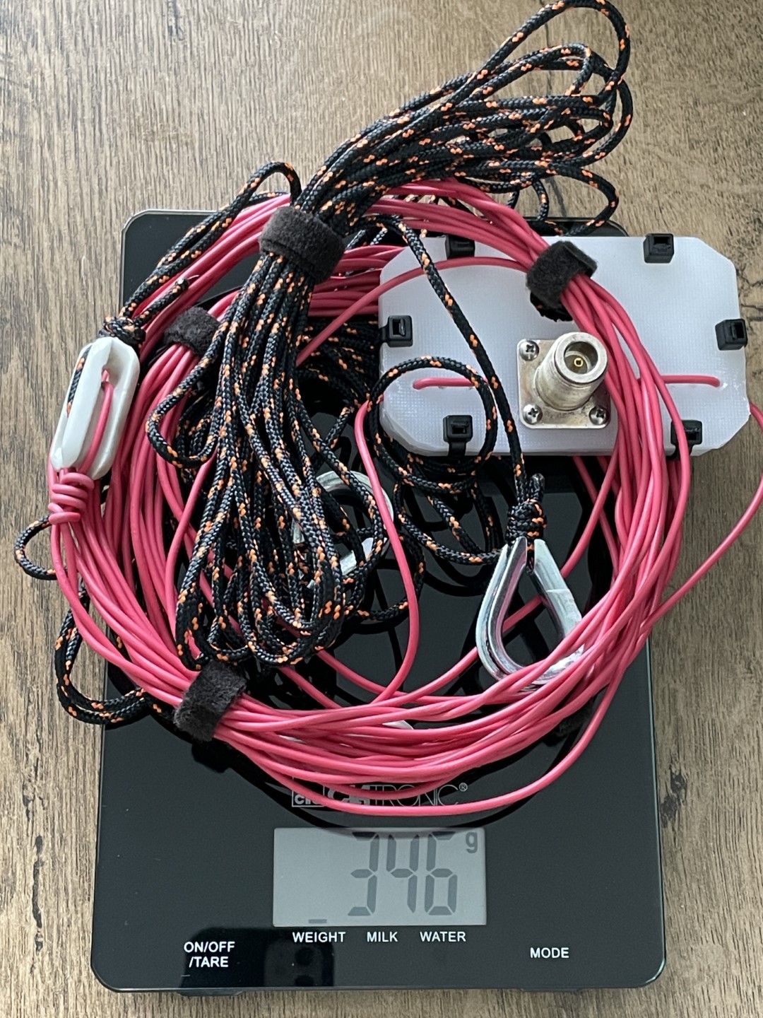
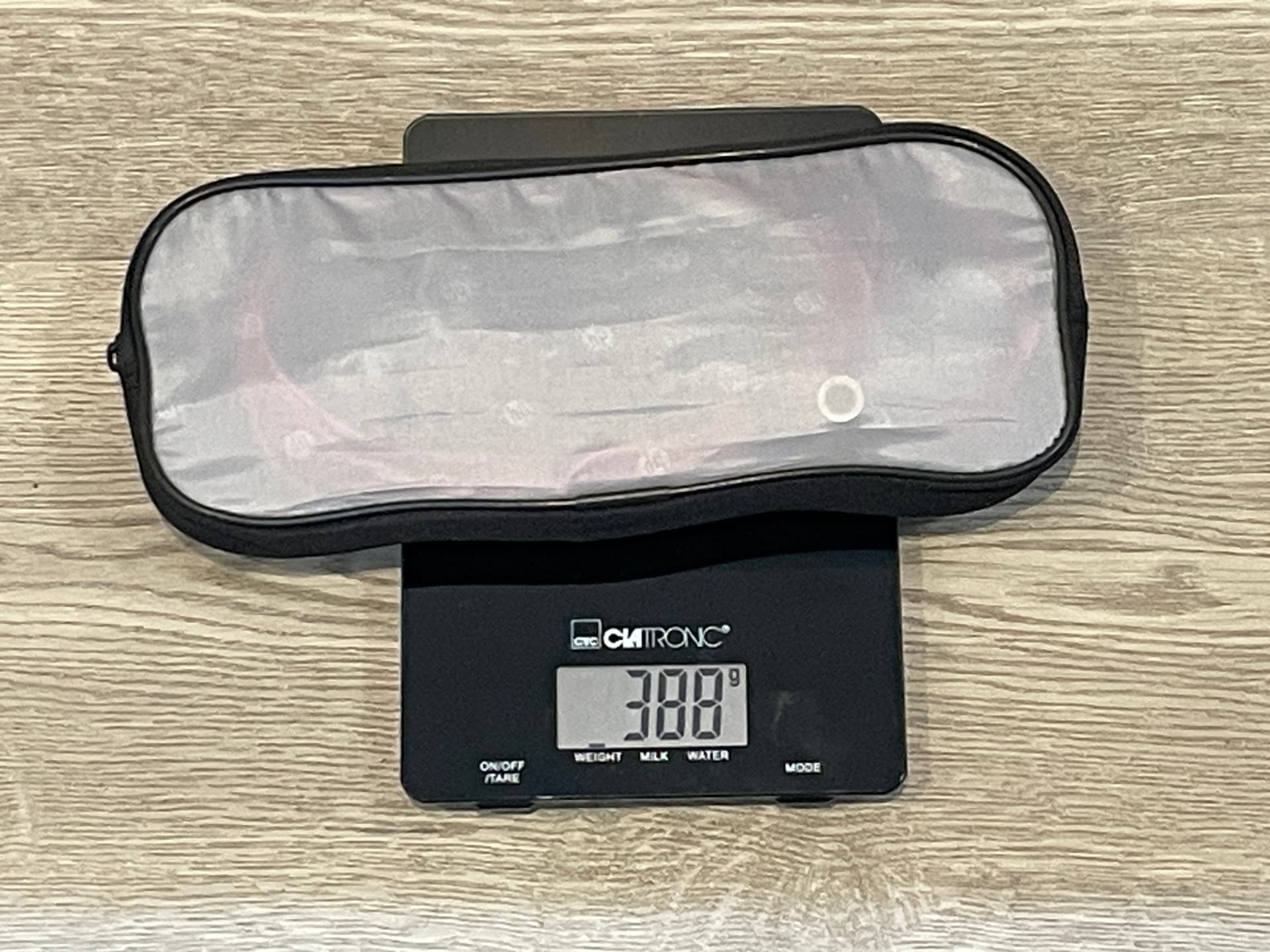
Although not looking at weight reduction, I weight some of the kit for curiosity sake:
- 20m dipole complete - 346g (388g packed)
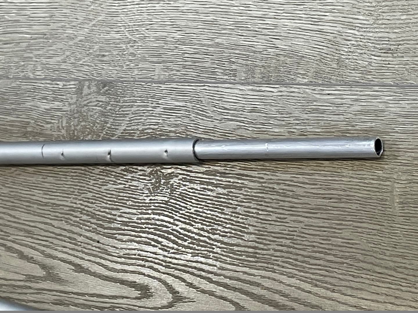
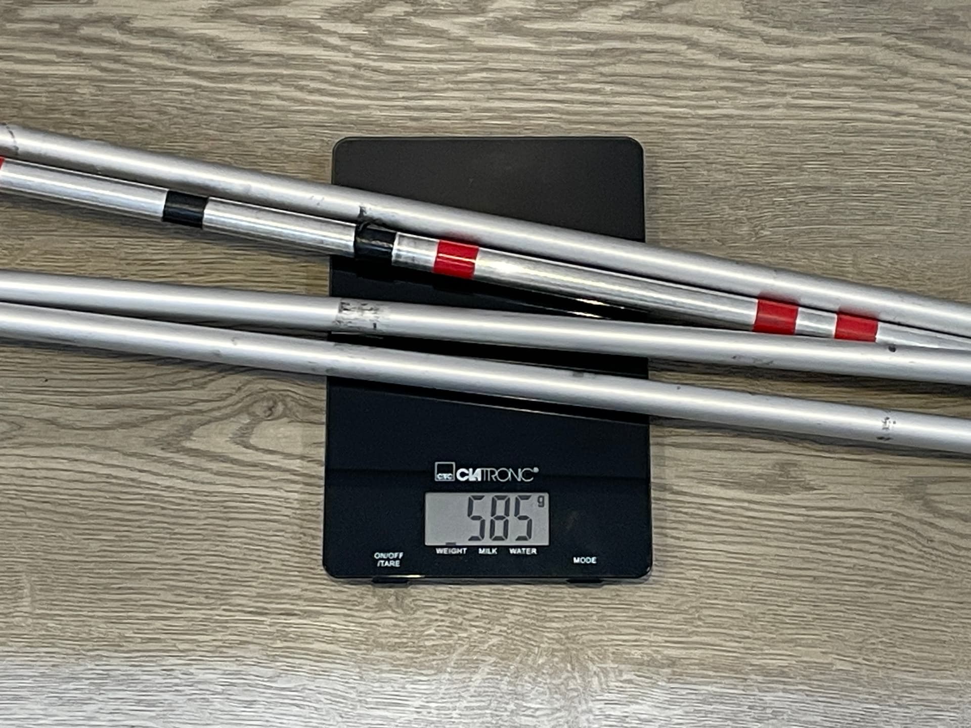
- 15mm aluminium collapsible mast (3m) - 585g
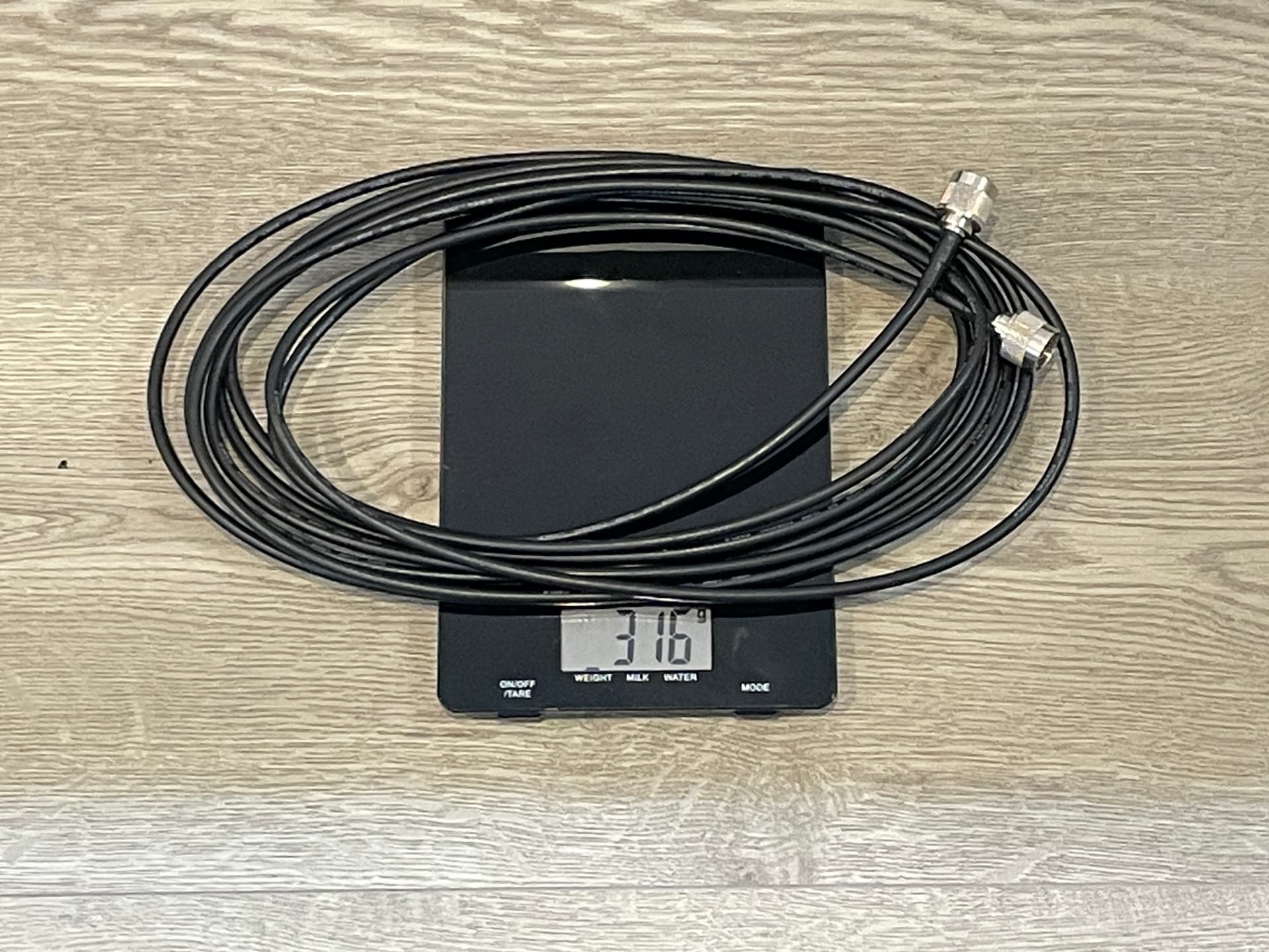
- 6m RG58 N-N type cable - 316g
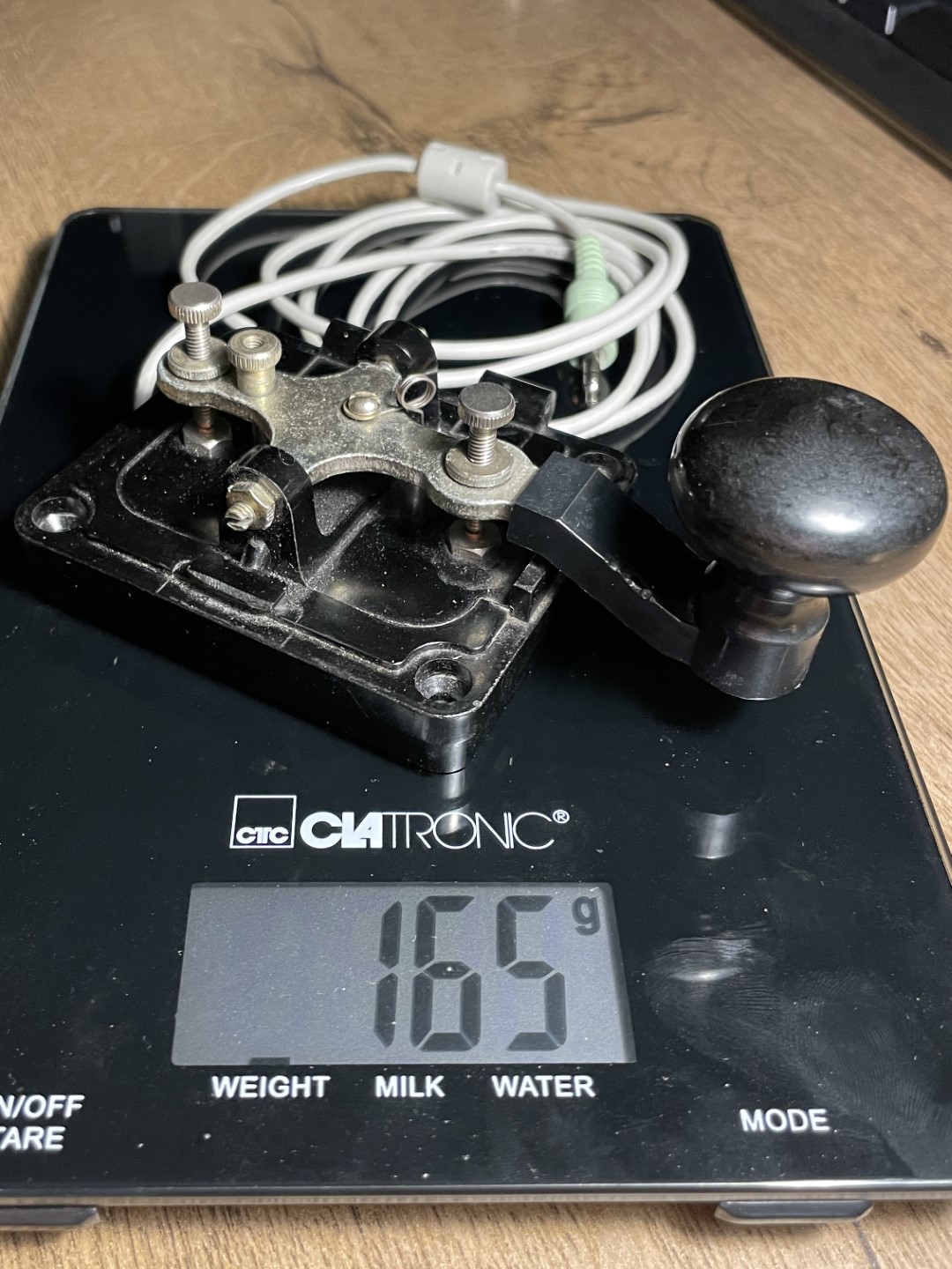
- Straight Morse key - 165g
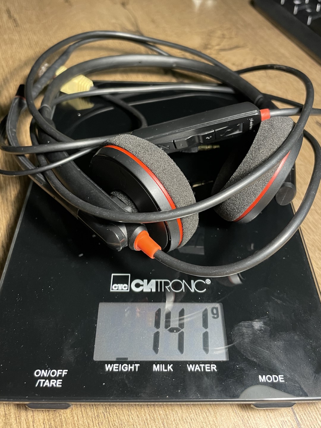
- Headphones - 141g
All going to plan, in the new year I’ll be looking at getting a higher mast and more HF bands.
No se discute, los FT857/817 son unos tanques. También tengo un FT857 y al pobre lo expuse a todo, desde nevadas, lluvia, polvaredas y hasta varias caidas que me hicieron pensar que no volvería a encender.
También recuerdo haber visto un video de alguien operando un FT817 cubierto con hielo.
Tremendas bestias!
I really like the FT-817. It might not be the best, but it can do almost anything; you just need a good antenna. It’s ideal for those who want an all-in-one device and weighs only 1 kg.
Yeah, I was looking at 817 too. The only thing it was not available immediatelly and then a local CBer has offered me a swap of 857, so let it be. I like the option to run full 100W when needed without some extra boxes hanging around. Eg. running 50W today at Lugnaquilla EI/IE-001, has for sure saved me extra time not to freeze to an ice statue.
For sure! And knowing that the 857 is a battery eater, I always use it at QRP levels, but when the fourth QSO is elusive, I increase the power up to 25 watts and et voilà, the fourth QSO shows up and I leave happy with the activation points.