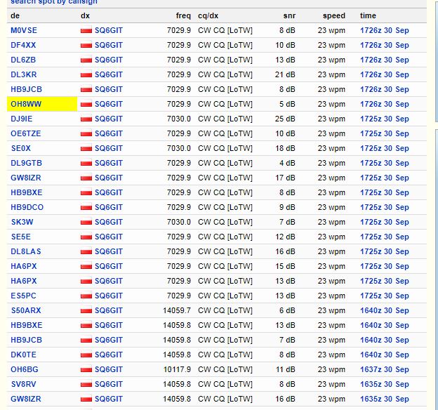
As a happy owner of MTR3b, I have found out that my unit sends perhaps around 100kHz lower than the display or sound indicate. I mean that if I am at 7.030 MHz, reversebeacon.net would rather show I am 7.029.900. It is similar on 10 and 14 MHz. (see screenshot below)
I found out in the manual that it is possible to calibrate this with an oscilloscope, but I do not have that equipment - is this possible to do this just without by pressing the arrow twice during the procedure based on the average readings of reversebeacon.net?
Has anyone tried to calibrate the frequency in MTR3b? I don’t want to spoil anything, it would be disappointing to spoil it instead of fixing. At worst case, I can stay with it and keep adding 100kHz each time I tune in the desired frequency.
I don’t think you should risk trying to correct your MTR frequency without having some means of measuring frequency.
Your suggested method is unlikely to work - you have no idea whether the rig has already been calibrated or not (I would think it has). A calibration value is probably already applied and without knowing what that value is, you can’t use it as a baseline.
Entering the calibration mode will erase the current calibration value and will start from 0 correction. The rig determines it’s own frequency correction factor by setting up a 10 MHz signal which then you tune up or down using the buttons on the rig to exactly measure 10 MHz. The difference between the original 10 MHz signal and the corrected signal then becomes the correction factor stored in the rigs microprocessor.
It is possible to use a computer soundcard using an audio spectrum analysis program and a commercial HF radio, measuring the beat note between the MTR 10 MHz signal and receiving radio. Eg. 10 MHz minus 9.999 MHz equals 1 kHz.
If I were you, I’d live with the ~100Hz error and maybe just tune a couple of clicks if you want a specific TX frequency. I find that RIT is nearly always needed as the receiver is pretty sharp anyway. There’s no provision to alter the CW offset and the audio chain is designed to peak at a particular frequency ~600Hz I think - your perceived ‘error’ in sound might be due to being more used to a higher offset say 700Hz which is the default for a number of commercial rigs.
Thanks Collin. As activator - theoretically yes, I can even forget the freq adjustment as I just tune up to a free one and call CQ which gets picked by RBN anyway, so theoretically not an issue at all.
My MTR5b (yes, I know it is fetish to have them both… ) - it has also 700Hz side tone and transmits exactly in the right point.
I have just been reading the manual, and it seems the procedure for a non-experienced “technician” like me may indeed bring more trouble than help, so I will just live with the 100kHz correction. Or if I meet anyone providing such service I may request them for help.
The frequency error is not a problem at all - it’s just annoying if you like whole numbers!
I think it’s important to remember also that the frequencies reported by RBN stations are not 100% accurate and they don’t seem to be rounded up. A frequency of 7.02999 would still show as 7029.9, so your rig might be closer to ideal than you think.
I have also noticed that temperature can have an effect on the reference oscillator - calibrating in a cosy lab might lead to a frequency difference on a cold summit.
Regarding calling other stations - the offset is fixed so just tune the station for the best reception and call, the TX frequency will certainly be within other station’s pass band, and I’m sure they’ll have RIT too!
My first run MTR (kit, two band) has a small frequency error, I didn’t have the means to calibrate it exactly at the time of build. I just live with the error, it’s around one click out, so less than 50Hz. It’s simply not worth going through the whole calibration sequence again.
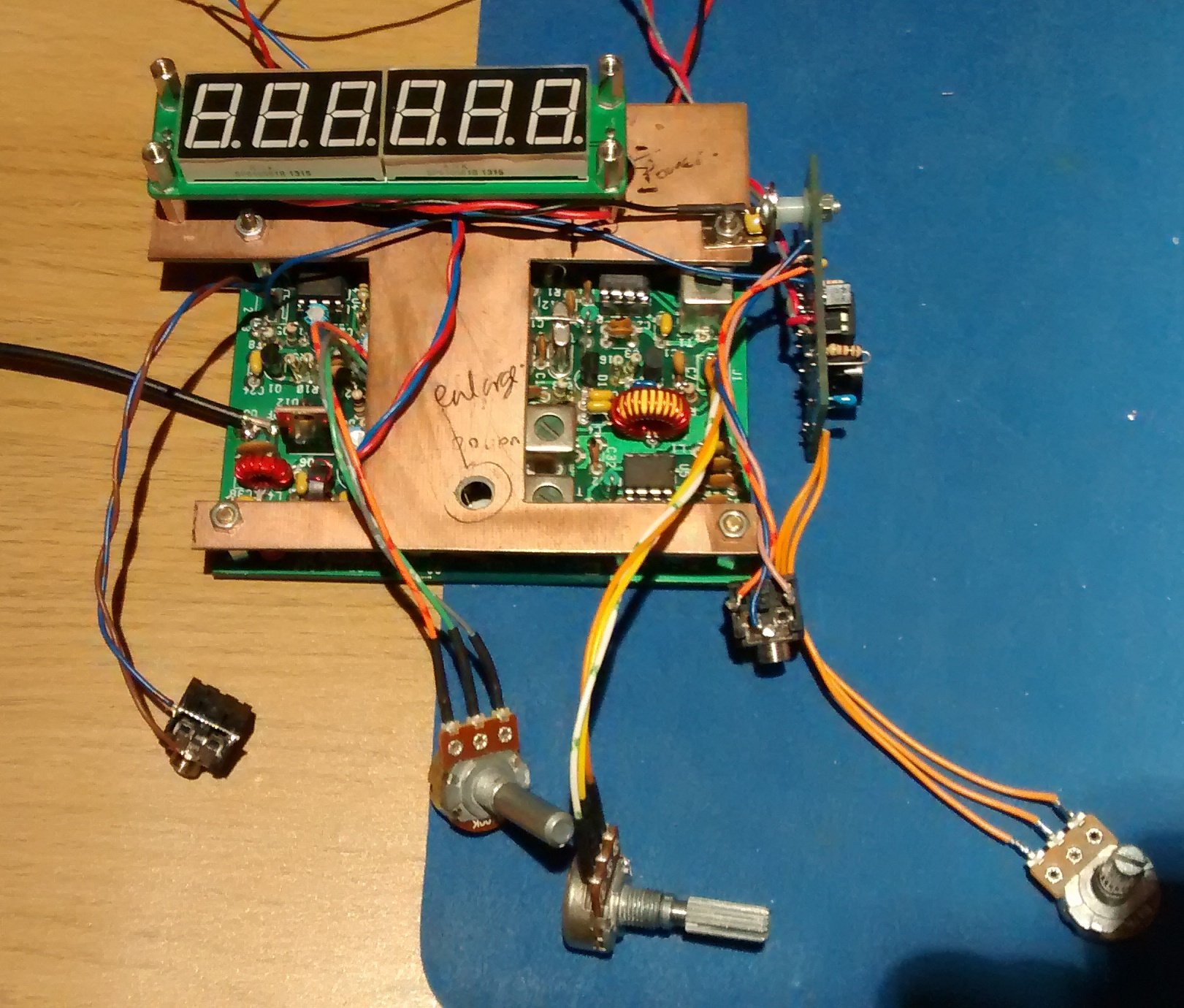
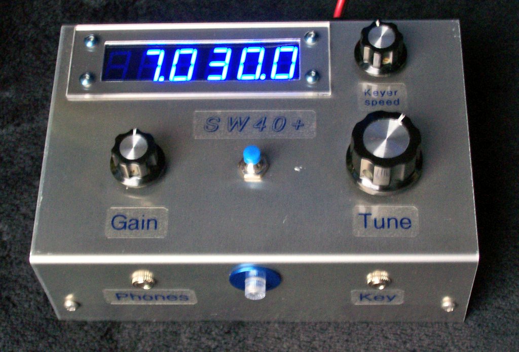
I found that the cheap frequency counters available via Ebay are actually pretty good. I had the 6 digit version, but there are also 8 digit versions for a small increase in price. My counter is now built into an SW-40+
my MTR-3B has the same issue here and I miss equipment to do a proper alignment…
What I did:
use a secondary rig at home to hear in the most common SOTA frequencies
40m: 7032 / 30m: 10118 / 20m: 14062
Send CW with my MTR and fine tune the frequency on my MTR until the tone I hear on the secondary rig is in the center of the passband.
Then Memorise these freqs on the MTR as the default when starting the rig (Menu M)
That way I always have the center QRG when I am going to start an activation.
In the other hand, If I find the memorised QRG in use then I QSY 1 up or down but then I miss the frequency correction…
I had my suspicions when calibrating a ‘customer’ MTR that this issue might be a characteristic of the design. Despite my best efforts, the rig was consistently a few tens of hertz off frequency. In the end, I deliberately calibrated slightly off, having worked out the error and got the rig pretty near to where it should be.
It’s amazing how hams now worry about a few tens of hertz, due to waterfall displays etc! I remember the old analogue VFOs and frequency readout within 1 kHz
I picked up an MTR-3B at the RSGB Convention in a very advantageous deal.
I used a non points scoring activation of Birks Fell G/NP-031 last month to give the MTR a test drive. I worked a decent number of stations but received signals seemed / were perceived / to be low. When I checked the RBN later I noticed that most of the hits were slightly off the frequency which I had set on the MTR.
My gut feeling turned out to be right - the RX band pass filters were seriously out of tune, in fact it was as if they were set in the worse possible position.
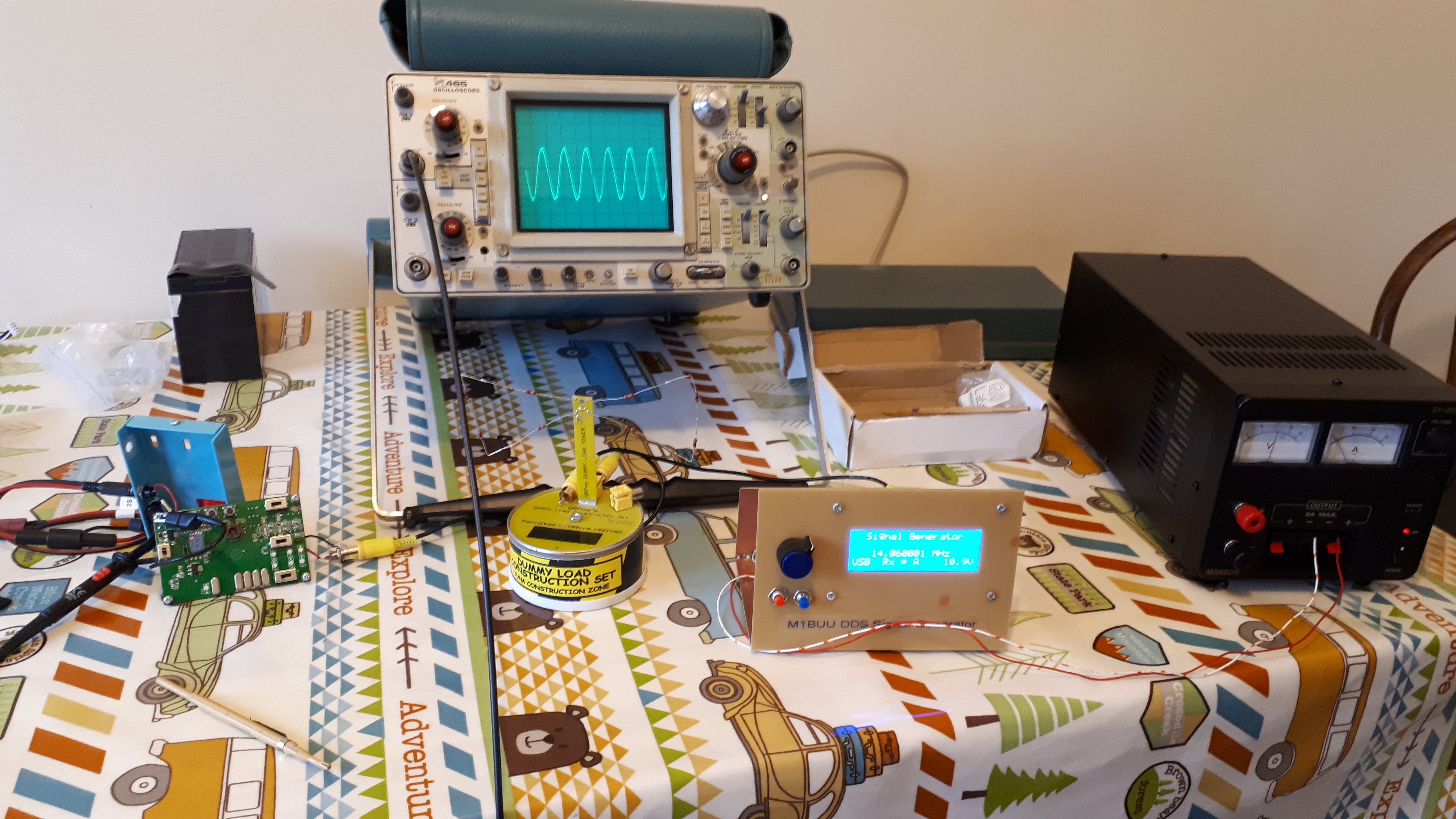
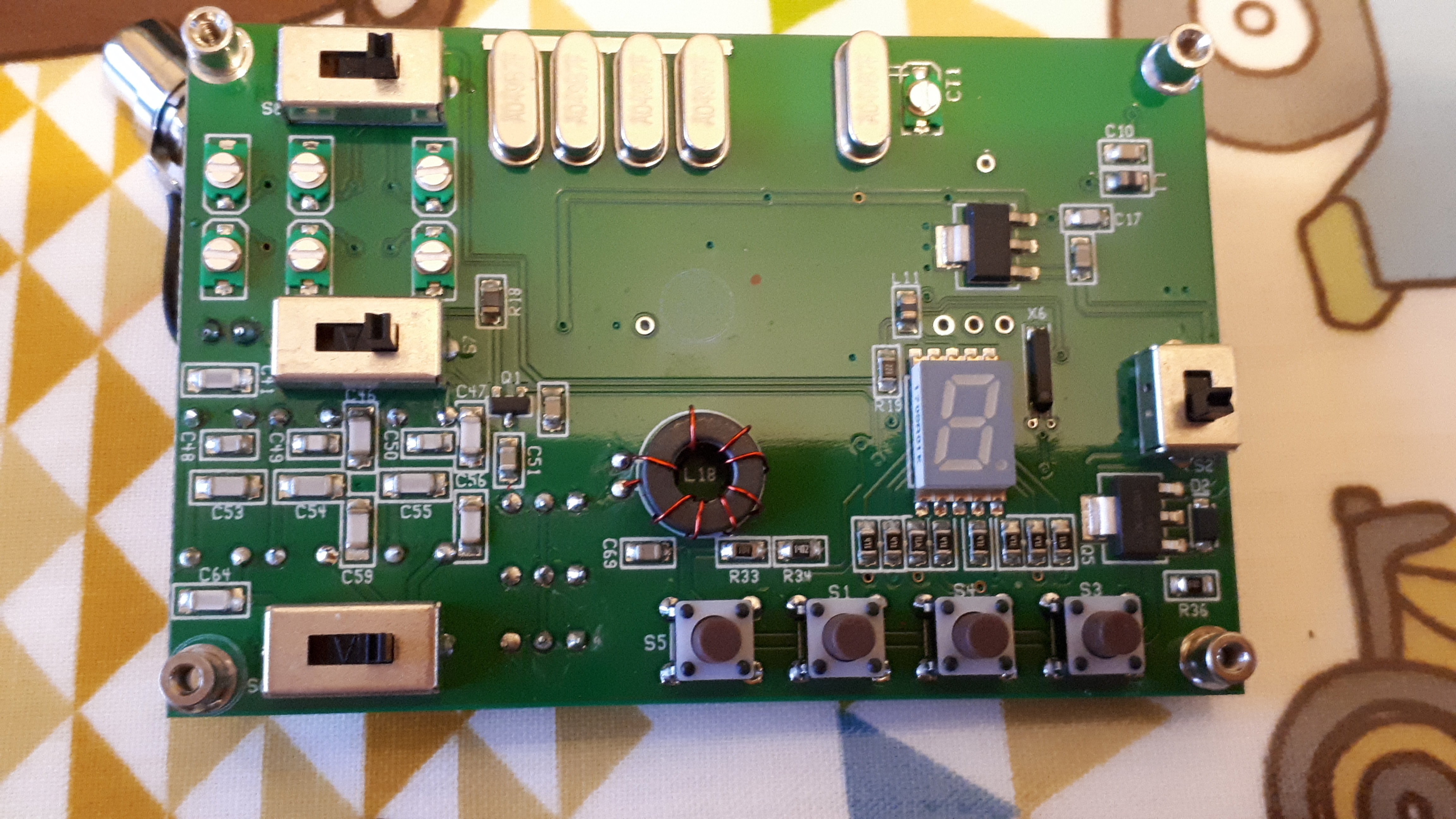
I calibrated my MTR-3B today, it involved removing the phono socket and removing the PCB. Once the PCB was free from the housing, I was able to get at the 7 small trimmers on the display side of the board. I let my frequency counter warm up for quite a while (I did a pile of clothes ironing whilst waiting!). I verified my frequency counter using a GPS locked oscillator.
The calibration routine itself isn’t too bad, it’s just a case of measuring a 10MHz test signal and adjusting for exactly 10MHz. I also tweaked the IF frequency and BFO for the best response.
Using my ancient 'scope and a home brew signal generator, I was able to loosely couple a test signal via a leaky dummy load into the MTR. It was then just a case of feeding in a 40m, 30m & 20m test signal and peaking the rx band pass trimmers for each band for a maximum response. It was clear to me at this stage that my MTR had never been through a BPF alignment procedure. To be noted is that if the test signal is too strongly coupled, then it’s difficult to find the actual peak. I find that laying the signal generator output lead next to my special leaky dummy load works really well. Using a dummy load means the rig is nicely terminated.
After the calibration procedure I then had to rebuild the rig putting the PCB back into the enclosure and soldering the connectors where needed. I found that the wire used for the connectors was very thin and was easily broken. I remade all of the connections just to try to prevent future failure.
 ) - it has also 700Hz side tone and transmits exactly in the right point.