Minion Mini

I did a joint activation last Saturday with Karl (OE6LKG) on OE/KT-098, Peterer Riegel. The weather was very good and I was looking forward to trying out Karl’s new Minion Mini transceiver from QRPver:

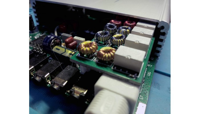
The rig itself is incredibly small for a 9 band transceiver, and relatively simple to operate. I charged up a LiFePO battery so we would have the full 8 watts+ out. The walk up was lovely, and the area was noticeably cooler than in the city, it was a pleasant 18C. We got to the summit and set up, using an OCFD, 10m mast and Elecraft T1 tuner.
The first thing I noticed was that there is no iambic keyer built in. You could use a single lever paddle fine, just no squeeze keying (to the best of my knowledge). Thankfully, the Palm Paddle Code Cube makes a very good external keyer for this rig, so not the end of the world. However, when we started to call on 20m the problems really began: we were getting spotted OK, but could not hear the answering stations! This caused a lot of confusion, for which I am very sorry. I would have posted earlier, but I had to take the rig home and go over it thoroughly to find out what was happening. One of the menu settings was CW detune, which detunes the receiver from the transmit frequency. On the hill, by default, it was set to 700Hz. Naturally, I set it to zero and called again: still no joy.
In the end we gave up and used my MTR3b (thank God I took it along as a spare). After much more fiddling and changing of antennas we finally got the summit activated. Thanks to everyone who had the patience to stick around and work us.
Well, back at home I eventually fished out the Minion Mini and started to have a play around, using my KX3 and panadapter to see what was going on. I found out that to receive on the frequency you call on, the receiver must be detuned to exactly 500Hz. Which explains why 700Hz and 0Hz did not work for us on the hill. Now. I do not have as much experience as some, so I’m not sure quite what to make of this setting. I’m used to receiving on my transmit frequency by default, and changing that only when I want to work split of something. Having worked out how to set the radio up for a QSO, I decided to put a call out on 14.0350 MHz and see what happened. No one came back to the call so I had a look on the RBN network to see how I was getting out:

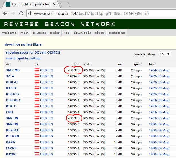
What I immediately noticed was that I had been spotted on the second harmonic (28.070 MHz) at a higher level than some skimmers were hearing me on 14.035 MHz. I reset HDSDR for 28 MHz and sent out an RBN test on 14.0350, and this is what the panadapter showed:

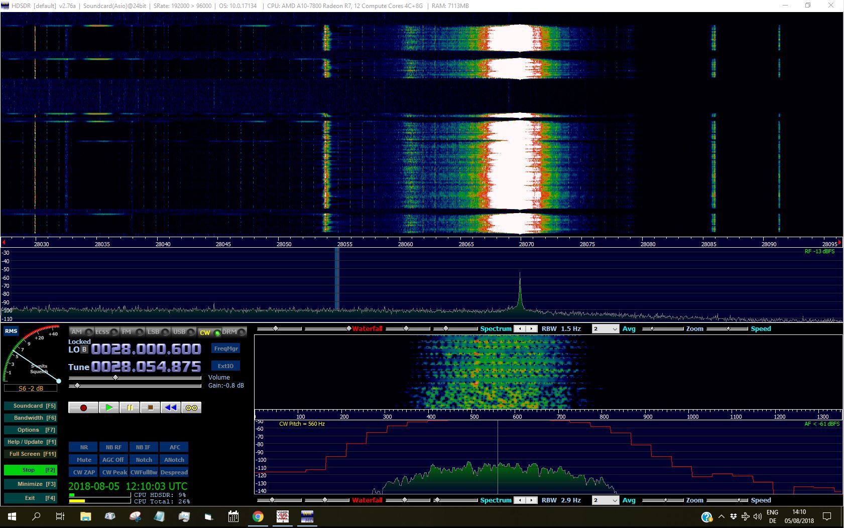
So definitely spurious harmonic emissions, not just in my area, but loud enough to be picked up in Sweden via sporadic E (well at least 10m was open HI HI). Like I said above, I’m no expert. So if anyone has more to add on this then I would be very interested. I tried to contact QRPver, alas to no avail.
73 de OE6FEG / M0FEU
Matt

3 Likes

Last year I helped a local ham with a dds vfo for his homemade qrp direct conversion transceiver, and I had to include a receive offset lo, because of the same thing you were experiencing. With a signal generator we started testing and the incoming signal would be heard a bit from the dial freq. ( I don’t remember how much of an offset I added). I’m guessing the incoming signal was “zero-beating” the lo of the dc receiver.

Looking at the minion mini page, it says that there is an software update happening.
Hopefully, that solves the issues.
Other than that, it looks like a nice little trx, too bad they didn’t include a keyer though…

1 Like

OK, that makes sense. Thanks for enlightening me there. The fact that 500 Hz is about the same as the CW tone did occur to me, but I couldn’t see how that would be a problem. I’m still in the dark regarding the spurious harmonics, is that normal?
Cheers
Matt

I would say that it depends of the level of harmonics…
If memory serves me right (hey, I’m a John Deere mechanic), some 40db choking of the second harmonic is desirable.
Interesting when looking at the trx pictured, I see no lpf’s in the form of toroids. Maybe it’s built with smd L?

1 Like

Hi Matt,
Direct conversion rigs always have to design in some shift between the frequency used as the LO for the receiver and the frequency used by the transmitter, on CW. If you didn’t have any shift any replies on your exact carrier frequency would be apparently at zero beat in the DC receiver. This is no use at all as you would not hear them. Therefore the oscillator in your rig must be on slightly different frequencies when transmitting and receiving.

Setting it to 500 hz offset should mean that a reply exactly on your transmit frequency produces a 500 Hz beat note. 700 hz offset => 700 hz note.

This is probably what is behind the recommendation to set an offset between tx and rx. It isn’t an offset between the signals on the air, its an offset between the on air signal transmitted and the LO/ BFO frequency required to hear a signal on that frequency as a beat note of the appropriate tone.
Hope this helps,
73 de Andrew vk1da/2uh

2 Likes

The schematic, RF_AMP.jpg, shows only one low pass filter between the PA and the antenna socket. It would be appear there will be no attenuation of harmonics that fall below the cut-off frequency of this filter (estimating/guessing at about 35MHz).

1 Like

That helps a great deal, of course. The instruction manual could perhaps have mentioned that. I did RTFM before posting.
cheers
Matt

Hi Matt,

it is a bit surprising that they didn’t mention that aspect of the DC receiver. other equipment that does similar things includes the Pixie tiny cw transceiver being sold as a kit or built-up, on the various auction sites. it works in essentially the same way.

As a teenager in the 60s I used to monitor my transmissions occastionally by listening on a BC221 “frequency meter” which contained a calibrated osciallator and a detector. The headphones plugged into the BC221 would allow you to hear your transmission on any amplitude based mode, and if you listened carefully you could observe key clicks and hear distortion in an AM or SSB signal. When you stopped transmitting, you could hear the signal from the BC221 and it would be offset from your transmitter frequency by the amount of the beat note, and if you play games like that you get to know almost intuitively how these things behave.

Perhaps the writers of the user manual assumed similar backgrounds in users. But that would not be safe as now almost nobody uses that kind of equipment to monitor transmissions or measure frequency. Most equipment now has a digital readout which is more or less reliable in indicating frequency.

73 Andrew VK1DA/VK2UH

1 Like

hi Matt,
your other issue was the harmonics of the 14035 apparently received on 28070 in Sweden at a pretty good strength. That does seem fishy to me. It would require a similar power level on 28 to the output on 14. While that’s possible, unless your antenna presents a reasonable impedance on the second harmonic, which is unusual unless it’s a trapped antenna and fed directly rather than through an ATU, it seems unlikely.
I think there are many instances of reports from RBN receivers that turn out to be unreliable or unbelievable for various reasons. The variation in sending speed, though slight, seems odd. it doesn’t add up to a credible report, in my opinion. 10m may have had a sporadic E opening, but even a class C amplifier would have a reduced power on the second harmonic, by say 10 or 20 db.

And then there’s the antenna impedance.
The Elecraft T1 tuner you were using would not be likely to present a reasonable (let alone 50 ohm) impedance to the radio on both 14 and 28 mhz at the same settings. It could well have a high pass configuration, ATUs are usually not a low pass network and certainly not a bandpass filter.

But overall, I am inclined to think that report is spurious, I can’t explain why it is on the second harmonic, but somehow it seems incredible.

73 Andrew VK1DA /2uh

The RBN net test was done at home with no tuner on a standard OCFD that was 1:1 at 14MHz. We only used the T1 tuner on the mountain one time, but didn’t understand the need for detuning the receiver, and so could not hear the answering stations. If I get time I will try to do more tests at home. The Minion Mini would still work well with a Fuchskreis, as this would provide the necessary fitering on the output; assuming that the RBN net data is not spurious. I have never been incorrectly spotted by RBN in my time as a ham, but there’s a first time for everything I suppose. Thanks for all your input anyway.
de OE6FEG/ M0FEU
Matt

Just a quick update on this issue of bandpass filtering. Having dug a little deeper, it seems that there is a bandpass filter option available when you order either a Minion Mini or Minion SDR:

By the look of the photo, the bandpass filter board fits inside the enclosure; so an acceptable solution in that respect. With the bandpass filter fitted, I’m sure the problems I encountered would be solved.

In this case, I would say that the Minion Mini or Minion SDR may well be of interest to SSB enthusiasts, as it is very small, and I measured the output power as high as 16 watts on some bands; albeit with a broadband lowpass filter instead of the bandpass filters. It looks like there is also a built in keyer now, at least in the Minion SDR.
I still find it bizarre that the site does not make the filtering situation clearer. Why would I want a radio without built in filters? OK, I might want to make my own, but then they would (probably) be external to the radio. I don’t know of any other manufacturers that make the bandpass filters an optional extra in order to get the list price down.
73 de OE6FEG
Matt

Because you’re a CBer?