I’ve wanted to have a go at having some PCBs made for a while (years actually!). I have made a few attempts at getting going with CAD software but I always found the learning curve too steep. At the RSGB Convention in 2019, I was chatting with Dan, M0WUT (occasional SOTA activator, keen CW op, PCB wizard and Yorkshireman like me  ) and he encouraged me to have another try with PCBs and promised to be at the end of a message should I get stuck.
With Dan’s tips and encouragement, I put together my first circuit board in Kicad a few months ago. The learning curve was very steep for me, and my poor little netbook seems to be under powered for the task. However I persevered and I was excited to have the design turned into a board.
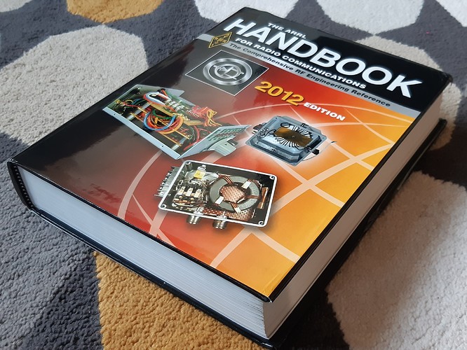
After Christmas I decided to attempt a more complex project and I have recreated a classic QRP rig. The schematic and firmware is contained within the ARRL Handbook CD, which comes with the ARRL Handbook. My Handbook dates from 2012 and I won it at the G-QRP Convention at Rishworth.
I produced the necessary files over a few weeks, doing a little bit at a time. I used JLCPCB to manufacture the boards, it was a simple process of uploading the .zip file containing the 8 PCB Gerber files. The JLCPCB tagline is 5 PCBs for $2!
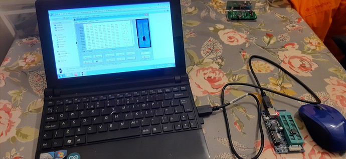
Whilst waiting for the PCBs to arrive I ordered some 12C508A PIC microcontrollers. The 12C508A is an ‘OTP’ part, which means One Time Program. Basically you’ve got one shot to burn the code! Thankfully my cheap Chinese hobby grade PIC programmer worked absolutely fine and I burnt 4 chips without a problem.
K150 PIC programmer burning the .hex
Test mule, testing the home burnt chips.
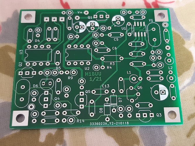
The PCBs arrived on Tuesday, around 2 weeks after ordering, and they are very nice.
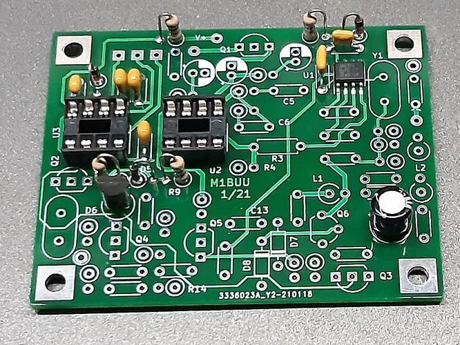
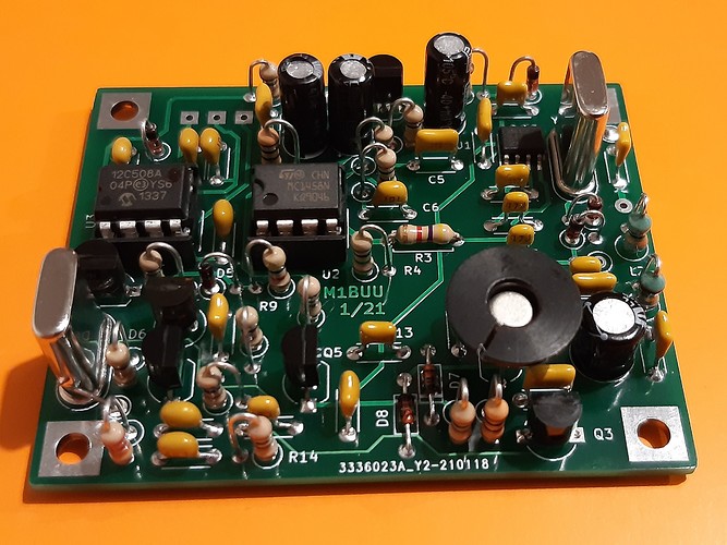
I’ve had a few sessions carefully building a board, checking things as I go. I’m pleased to say that my board fired up first time with no debugging necessary, I even got the dits and dahs the correct way round!
Yet another rig to add to my SOTA rig pile to try when lockdown is lifted!
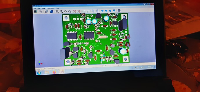
Drawing the circuit board in Kicad - (3D view mode)
Pleased with the PCB
I tested the shunt regulators first (didn’t want to fry the PIC!) then added other components.
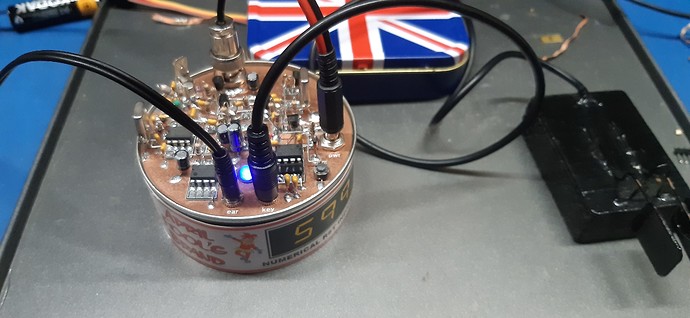
Board finished.
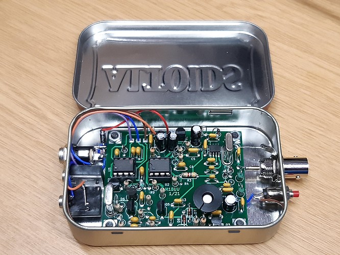
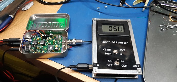
Built into the almost obligatory Altoids tin case.
500mW output on 40m
73,
Colin
M1BUU
(Full credit to Dave Benson, K1SWL for the original design and PIC firmware)
