Because I purchased magic wire (DX-Wire UL) and feeder line RG-174, I am going to do couple of new link dipole for moving to use lighter versions. As good as existing models but lighter ones. Richard’s G3CWI Excel Design Tool is excellent, but I have a question. So far I have made “own” link dipole for every band. Now I have an idea in my head that if I had three band link dipole (for example 20-30-40 m), I could use it in some other bands too (with tuner). Am I dreaming or is it possible?
If it is possible what kind of practical variations could be used for covering bands from 10m to 40 meter? Let’s assume that I had two antennas.
Second question: has somebody used long wire antenna in Summit? If yes what kind of experiences you have had with it compared to link dipole? I am using 10m telescope mast and I could test that one too.
A 10m pole will take a length of 11m wire no problems as i use a 8m pole with 11m wire on it giving me a 1/4w on 40m via the 9:1 unun home brew using a MFJ949D tuner. Just twist it around so slack is taken up won’t be much.
Or as in my second part of me portable duel antenna am using 22m of wire for 1/2 wave on 40m in an inverted L shape. again 10m with 1m around the pole will allow 11m to spin off as long wire inverted L . But do match it with a 9:1 unun.
With tuner as above mentioned i can tune in all bands 80 40 20 15 and 10m on both antennas. and yet will ever forget me first contact on a summit with the 40m vert antenna into VK5PAS on 10w on 20m was well result for testing out me antenna for first time and yet noise levels at that summit were low compared to home QTH.
I got me wire from sotabeams light weight and loads of if broken simple to replace.
Do have an 11m wire as counterpoise used on both antennas. But not changed it to a 4 legged CP but still over all totals 11m length not tested as yet
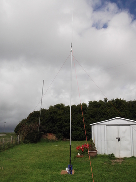
My 40m vertical 8m pole with 11m of wire on it
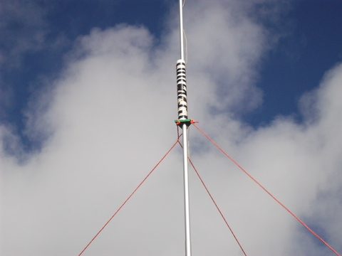
This picture shows the wire coming from the unun leading upwards to the coil bit spaced out to lose 3m of the wire length and rest goes to tip give 8 m antenna BUT over all length of antenna still 11m long giving the 1/4w on 40. Me inverted L is just longer length of 22m in same fashion giving me 1/2w on 40. The coil bit was on ground but felt better i moved to higher part of the pole. still works well. all tuned via the MFJ949D tuner
So my experiences with wire portable antenna with tuner so far . Easy to errect and store away and light weight no messing with putting in joiners for required bands just tune in and away ya go. Yet to sort out base better to reduce stuff to carry up summits but base is good for other field portable areas.
Thanks Richard, the newer designing tool is even better! After couple of minutes I learned to use it with trial error method. If and when 40m replaces 15m. It means that having 3 band link dipole (20-30-40m), you can run 15m too – four bands. Having 5 band link dipole (12-17-20-30-40m), you can run 15m too – this is for six bands. Is it that simple?
Do I need in every case own dipoles for 12, 17 and 30m? 30m replaces 6m, but that band I do not use in Summits. 12m and 17m are very useful especially in those days when will be held contests.
Hi Saku,
There’s also a trick of adding a short extension to the 30m section of a bandhopper (or homebrew) linked dipole to make it work (rather well) on 10m. I did this for a couple of activations when the first part of the SOTA 10/6 challenge was on earlier this year.
An antenna has an impedance on any frequency that can be measured and a way can be found to match that impedance on that band. However the impedance may be very high and/or very reactive, which can be difficult to match to with a 50 ohm radio. The high SWR increases feedline losses in particular on the higher frequency bands, but that is not the biggest issue. To some extent the usability of an antenna on another frequency depends on what losses you are prepared to tolerate and what impedances your ATU can deal with. They all have their limits. The impedance seen at the tx end of the feedline also depends on the RF length of the feedline, which is frequency dependent. Some lengths are better than others, in that the impedance seen at the tx end is more readily matched with a tuner, or in rare cases, the perfect impedance of the antenna is replicated at the tx end due to using a multiple of half wave line lengths.
As a 10 MHz dipole is also resonant on about 31 MHz, an added short wire on each end makes it a usable antenna on 28.5 MHz with some odd lobes but slightly better in two directions than a plain 10m dipole. Similarly the 7 MHz dipole is resonant on 22 MHz and requires an extra bit of wire to bring it to resonance in the 21 MHz band. you might even find that the same extension wires could be used for both adjustments. For 18 MHz, the 14 Mhz dipole is a bit long and the impedance is quite highly reactive, but your ATU might be able to deal with the impedance. For 24 MHz, again the 7 MHz dipole being resonant on about 22 is near but still reactive, so depending on your ATU and the length of your feedline you may be able to use that on 24 MHz. It will be an experimental process and no single simple solution is likely, imho.
I built my own linked dipole with links to make it work well on all HF bands. I made 10m extensions to increase its overall length to 40m for use on the 80m band. No ATU is necessary but you do have to drop the pole to adjust the links when changing bands, and I think that is the major but only disadvantage of the linked dipole.
Alternatives: I looked into this a while back and concluded that the ZS6BKW multiband dipole (an improved G5RV in some ways) when used with the designed feedline and ATU is probably a really good way to go. ZS6BKW researched the range of impedances for various antenna lengths and came up with the dipole and feedline length that gave the best compromise. Those who use them either at home or for SOTA on hilltops have great results and that is the proof of the design.
Thank you for everybody about hints. Today I have three different field antennas: pure link dipole for seven bands, end fed trap dipole for four bands and 44 Foot Doublet. In the two first the wire is 1.5 mm2. Now I am going to make two new antennas: one link dipole for seven bands and another for four bands. Open issue for me is how the magic wire behaves when there is several mini-isolators, but let’s see.
By the way I found very interesting and easily understandable presentation about wire antennas:
An alternative method of bringing the third harmonic to resonance without detuning the first harmonic, as in 40m+15m, is to solder loading loops at the 15m high-voltage points - they could be straight lengths of wire but loops are easier to handle.
I use a W3EDP antenna, this is essentially a 26.5 metre long wire with a variable counterpoise, fed via a parallel tuned tuner. This has the advantage that band changing is done at the operating point with no need to move around changing links.
It is possible to buy low-loss twin lead (from Spectrum Communications) with an impedance of 100 ohms. With this you could make a doublet which with a small tuner (I favour the Z-match) will cover several bands, the lead being more convenient than 300 or 450 ohm ladder line.
I don’t think so, Walt, as it also radiates - the antenna works better if the counterpoise is somewhat elevated - and according to the article that I got the design from years ago you need a 132-foot counterpoise to operate on 160 metres (not that I have ever tried that!) To be clear, I run the counterpoise in the opposite direction to the main antenna, perhaps it is better to think of it as a modified Windom (in the modern sense.)
A true counterpoise needs to be a quarter wavelength in length on the band in use. The only band on which the 17 foot wire approximates to a quarter wave is 20 metres. As you correctly say, a counterpoise for 160 metres would be about 132 feet long. A W3EDP antenna is a modified end-fed Zepp. I used one for many years in South Wales and got very good results, although on some bands it performed better without the 17 ft wire connected.
Well, Walt, I think it is best regarded as a modified Windom: imagine a Windom-type antenna with the balun replaced with a parallel tuned circuit fed by coax, and the short end measuring 23 feet, 17 feet or 6.5 feet according to band. In practice I have added a variable cap with a shorting switch between the tuned circuit and the long wire which enables me to use a single length of “counterpoise” and achieve my aim of changing bands without having to get up and manipulate the antenna.
I suppose we could discuss terminology as much as we like, but the important thing that we shouldn’t lose sight of is that it is an antenna that works very well today although it was first constructed (by trial and error) in the 1930’s.
Nobody uses the original W3EDP, where the coil was inductively coupled to the tank coil of a 50 watt valve PA (the adjustments must have been a bit of a pig!) and, it is said, the “counterpoise” was run around the ceiling! (Radcom Dec 1936)
Incidentally, my version was modified from the version published in PW by G3BDQ. Just as any architecture of a 102 foot doublet is a G5RV, any architecture of a 25.6 metre end fed to a parallel tuned circuit tuner and counterpoise is a W3EDP despite modifications.
Not true. A G5RV antenna has a matching feeder section of a precisely specified length.
“The dipole elements are 15.55 metres (51.0 ft) and the
impedance-matching symmetric feedline (ladder-line) can be either 300
ohm (8.84 metres or 29.0 feet) or 450 ohm (10.36 metres or 34.0 feet)”.
The remaining feeder into the shack is low impedance coaxial cable, usually 50 ohms.
I use a 102 foot doublet as my main antenna, but it is not a G5RV because the feeder is 300 ohm slotted twin all the way to the ATU in the shack.
I refer you to Louis Varney’s article in RadCom, July 1984, pp. 572-575 “By far the most efficient feeder is the open wire type. A suitable length of such can be constructed in the same manner as that described for the open-wire matching section. If this form is employed, almost any length may be used from the centre of the antenna to the matching network (balanced) output terminals. In this case, the matching section becomes an integral part of the feeder.”
Like you, I use 300 ohm ribbon all the way to the shack (though when I get a round tuit I will replace it with 450 ohm in the hope that it detunes less when it starts to rain!) so both of us are using a true G5RV as described by the inventor.
Brian
A late PS - it also appears from the article above that the coax that Varney used was 75 ohms and not 50 ohms. However, I tried it before changing to the doublet form and it makes no detectable difference.
Brian, that’s an interesting idea, so you add a short length of wire as a kind of capacity hat at the point where the 15m dipole would have ended? I am unsure what you mean by a loop, are both ends connected? How does this not affect the fundamental resonance?