always depends upon what one is trying to accomplish. A 20M half-square is a 40M EFHW deployed in a shape that provides (DX) advantage on 20 (and 15). It continues to work fine on 40M, just like any other EFHW. On 20M the advantages include: needs one tree present and one pole carried. Because the verticals are upside down, that is, current high, it doesn’t need radials and isn’t lossy to ground, it puts two verticals in phase such that it has a lot of gain bi-directionally AND at a low angle (concentrated around 17 degrees), making it one heck of a DX antenna. It is EZ to deploy taking only minutes. - fred kt5x
PS… ONE time we deployed a 20M EFHW and a 20M half-squarehere (in New Mexico) to compare them during an S-2-S sked with Gavin, GM0GAV. He was inaudible on the 20M EFHW and worked easily with the half-square.
@K6EL. Do you have a pic or description of the webbing boom? I’ve thought about a 3 element inverted V yagi when each element is secured with tent stakes in the V position. Also considered forming the elements into a triangle with small gap between the ends of the radiator to minimize the width of the beam.
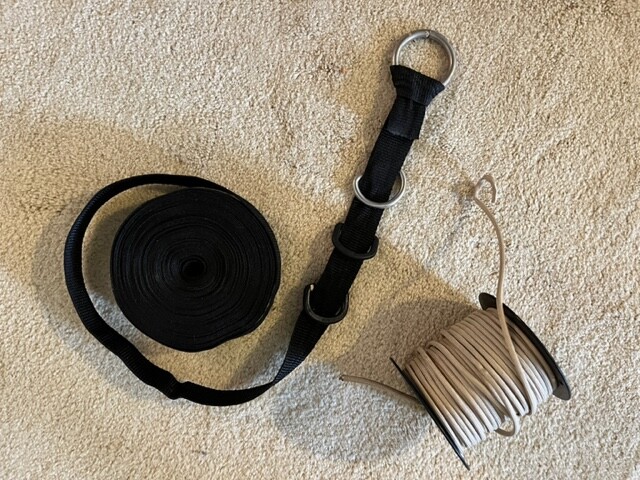
Mike … Pictured is a coil of one inch no-stretch webbing for the yagi boom, plus no stretch cord to extend each end into trees. Not shown is a sling shot to hoist fishing line over a branch, which pulls up the cord. Web and cord came from KI6J.com a few years ago.
@G4IPB. I’m running max 60 watts, but a short run of coax. Was the loop horizontal or vertical?
Loop was horizontal between trees. i had the ATU in the shack, then a 25m run of coax, then a balun (tried 1:1 and 4:1 - no ideal solution as I used it for several bands and it was high impedance on one, and low on another…) . It was still an excellent rx antenna.
@KT5x The ability to s2s with GM0GAV gives me hope. It’s why I want to try out something with low takeoff / directional gain.
Got a 49:1 TennTennas matching unit from Ebay in the mail today that will handle 60 watts. I’m going to start with exactly this configuration, then add a connector for the additional wire to turn it into a 20m bobtail curtain.
@K6EL Thank you for sharing the pic of the webbing. I’ll email KI6J to learn more about this design. Is the boom more robust to support the weight of coax feeding the driven element?
That and the weight of a balun and hairpin feeding the driven element. The boom is 25 feet long on 20 meters. Do you know anything about end-feeding a driven element?
@K6EL . On a Yagi, I don’t. My only Yagi use has been an Arrow Antenna on 2m.
I’m a novice at building antennas, but have built a qrpguys efhw w tuner and a sotabeams dipole kit and used a NanoVna to graph the SWR.
For an inverted-V Yagi, I assume I would try center or off-center fed as a dipole first. There would be an impedance mismatch for my tuner to deal with.
That was bothering me, too, Richard, as I would have expected more gain. On going back to the article he actually wrote “The gain at the low take-off angle of 5 deg peaks at -2.6 dBi which is 3.5 dB better than a ground-mounted quarter-wave with a good ground radial system.” I shouldn’t have trusted my memory, it isn’t as good as it was!
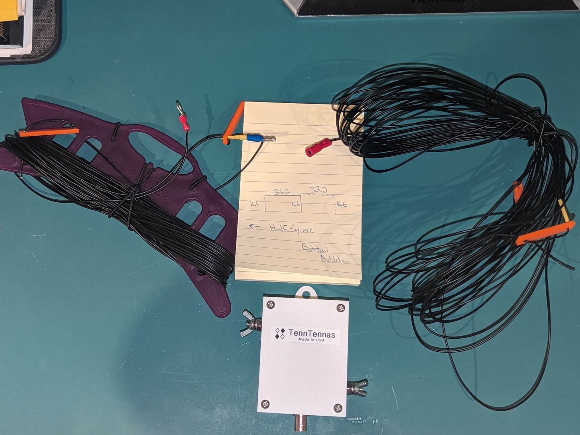
Left side is an end-fed half square for 20m. The verticals are currently 16 ft 8" to be resonant at 14.00. The top is 33.2 feet. I’ll trim it for 14.045.
On the top corner of the side of square that is fed from the bottom, I cut away some insulation and placed the male bullet connector seen on the notepad. This connects to the female bullet connector on the right side of the image. Connecting the right side adds another 33.2 feet horizontally, then down to a 3rd 16ft 8" vertical to create the bobtail. Strain relief for the bullet connector is created via the orange insulators. It’s fed with a 49:1 transformer that will handle up to 60w.
The orange insulators are placed on each corner to hoist the antenna, and on the bottom of each vertical. They will allow me to fold the wire back to trim to resonance on CW or Voice portion of the band via about a 6" adjustment. I will mark these points with heat shrink. Additional ring terminals will be added above the feed vertical to resonate in the phone portion of the 20m band. The insulators on the bottom of the verticals also allow me to peg each leg down.
I’m going to experiment with the verticals nearly touching the ground to about 4m above the ground to see the impact on SWR and how it should be trimmed. The wire can be reconfigured & deployed as an 80m efhw or 40m 1/2 square by adding 16 ft of wire and two additional bullet connectors. It weighs less than my SotaBeams linked dipole.
I’m heading to my cabin in a week and will be able to test and trim. The location, on a lake with steep mountains on either side isn’t ideal for the radiation pattern of the bobtail config.