Ok lets see if there is anyone on the reflector who can answer this better then. My “opinion” would be that as the main radiation will come from the vertical element it’s most important to get that correct and then trim (or fold back / fold out) the radials to support the vertical element on whichever band it is being used on.
Very interesting indeed but when I go QRP shipping it is not always in summer, it is also in winter and sometimes in the rain or with the dew of the night. So how to seal the tuning part of the antenna?
The whole QRP Guys unit could easilty go inside a plastic sealable freezer bag and be protected from the weather.
In fact I may do that in any case as it provides extra protection for very little weight.
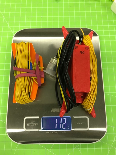
I am sorry to say that by extending the coax and adding 1.5m of rope for a sloped deployment (on carbon-fiber masts), I am now at 127 g, hi.
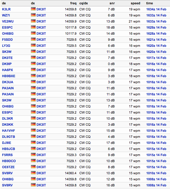
As for the performance: With 5 W, I got decent spots in NA on 20m and 30m yesterday. The SNR in Europe was a bit below my expectations, but I tested this on a flat yard surrounded by 4-story buildings. The low angle radiation might have gone into heating the buildings, hi. And likely the DL etc. skimmers got only the weaker high angle parts. Will know more once I have the time for a systematic WSPR analysis from a better location.
Edit: Note that this performance is with a single, elevated, resonant radial. The original design with four non-resonant radials will likely be weaker.
Thus, the original Vertical Antenna mutated into an angled multi-band dipole antenna, hi. This particular dipole (doublet) configuration has been discussed by some top antenna experts since the sixties. For convenient fine tuning of portable upper and outers, an ATU is commonly used.
Hi Martin,
thanks for sharing this kit.
Back in 2013 I built and performed a number of activation with a homebrew Multiband vertical. It performed well, but nowadays I rather prefer to use my multiband EFHW.
My vertical also had a coil for 30m and 40m and was a true quarter wave for 20m.
To improve performance a bit, my coil wasn’t in the base but elevated about 2 m in the middle of the aerial. I also used a single elevated radial to fine tune SWR and was easy to set.
Nice catch! They have more articles of interest like Antenas I and II as well for perusal among some other articles. A good way to learn spanish as well since the translation is very funny
I have noticed that the maker recommends using a single radial with the budistick, as it is easier to fine tune the antenna when it is in lazy L dipole format than when you have 3 or 4 radials to tune, or need to adjust the vertical element.
However I understand that in such configurations, half the antenna current is flowing in the single radial and unless it is elevated, that half of the tx power is split between being radiated and being absorbed by the nearby ground, rocks, foliage etc, While the antenna impedance may well be adjustable to be a close match to 50 ohms, or is at least non reactive, that doesn’t necessarily translate into best radiation efficiency. Part of the radiation resistance is the loss resistance in the nearby ground, so exposing the antenna to that loss is undesirable.
While it is tempting to simplify a vertical antenna’s ground system to a single radial, and it looks good on an analyser or on the swr meter, using two or more elevated radials is better for dx and produces more radiated signal.
Perhaps one of the wspr-aided antenna comparisons will confirm that in due course.
I have always found that the Buddistick does need the elevated radial and many times you tune the swr by altering the elevated radial length.
When i left it on the ground I was not happy with the antenna.
Also the radial offers some directivity and I am sure the radial may radiate more RF energy than the short vertical element.
I think all the short whips would be similar.
I bought the newer version of the Super Antenna and their radials are full length.
Now that I joined the Linked Dipole Club I am convinced that is the better way to go if you can erect it on the summit , if not the vertical is the way to go. A proper 1/4 wave is ideal of course.
john ve3ips
I think everyone is aware of the BuddiPole Field Guide
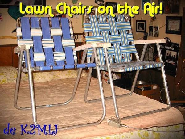
and now for extreme SOTA the lawn chair challenge is a good one!
Has anyone made up an antenna using the aluminum hiking poles?
First ham to SOTA the 2 lawn chairs on a Summit gets a beer paypalled to them! I am thinking the Austrians might win this one by submitting into Northern Italy.
It looks like the QRP Guys have had lots of orders recently for this antenna as I’ve only yesterday received notification that they are shipping this kit to me - 11 days after I ordered it. I wonder how long it will take to get here? it’s often far quicker to order goods from China, India or elsewhere than from the USA. It always seems to take longer with the USPS.
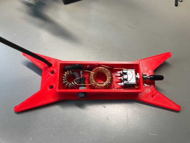
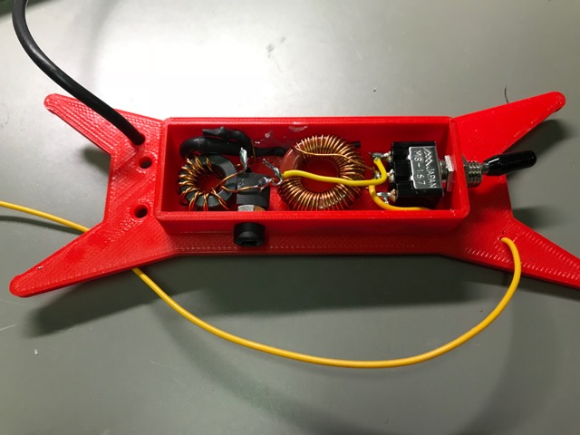
I use one single, tapped T68-2 core instead of two to obtain the required inductances for 40 and 30 m.
Instead of two SPST slide switches, I use a single SPDT 3-pole on-off-on switch, as proposed by Heinz, @HB9BCB.
I added a common mode choke in order to reduce the effect of unavoidable asymmetries between the radiator and the counterpoise.
Instead of four 10 ft. ground radials, my design can also be used with
a) one elevated, resonant radial, tuned for each band by winding up the remaining wire, or
b) three elevated, resonant radials attached to each other.
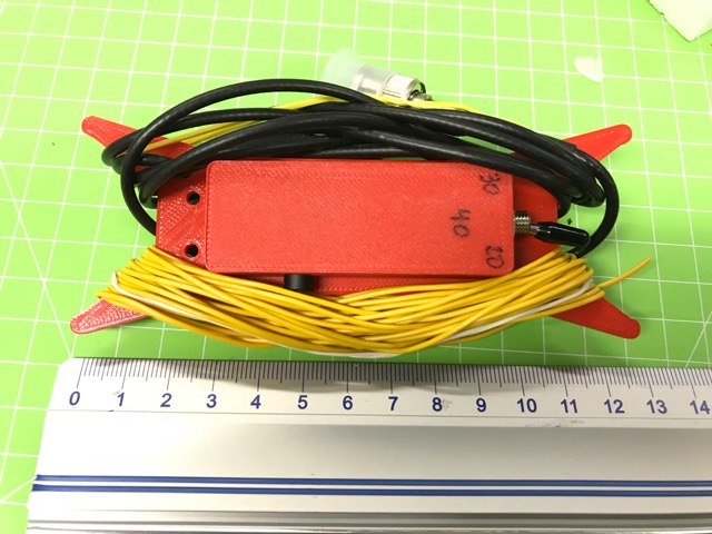
The enclosure is also a winder, same as with Packtenna antennas.
I have not yet tuned this one, because it is just too cold outside right now
Enjoy!
73 de Martin, DK3IT
Edit: The details of the tapped loading coil are as follows: With 0.5mm magnet wire, wind 25…26 turns, then add a short tap, then another 20…21 turns. Leave at least 10 cm on either end so that you can adjust the tap by adding a turn on one side and removing one on the other. Now tune the loading coil with a component tester or other device for measuring inductances. The total coil should have 11.5 - 12 uH, the 25…26 turns should have 3.4 - 3.6 uH. It is important to shorten the rest of the coil (i.e. the 20…21 turns) while measuring the inductance of the lower 25…26 turns. The 0.5 mm wire fits on the T68-2 core and should be thick enough for high efficiency and QRP levels.
I did the QRP-Guys (or rather the USPS) an injustice - the antenna kit has just arrived here today 5 days after they sent it. Now I have to wait for the wire I ordered for it’s driven element and four radials to come and the new on-off-on switches.
as for the counterpoise, I am now considering (and hope to be able to compare) several alternatives:
a) four non-resonant ground radials, as in the original design - not so much influenced by differences in the ground, but less efficient).
b) single counterpoise on a winder with markings for each band; fine-tuning for compensating differences in ground, same as @G8ADD has proposed.
c) three pre-tuned resonant counterpoises, soldered to a single 2mm plug with no winders on the end.
d) same as c), but with a small inductor for loading a shortened counterpoise for 40m. Will make the set of cps easier to manage on a small summit. Unclear impact on performance, likely more difficult to tune (narrower bandwidth).
e) single radial with markings and a variable L-network/transmatch for the counterpoise, i.e. adjusting the resonance of the cp by a variable inductor or capacitor. The advantage is that you will need no fully-fledged ATU and do not have to retract and redeploy the cp for a band-change.