I don’t have my analyzer in front of me, so I might have it backwards. Using my rig analyzer I’m constantly scrolling “left” to find what frequency the antenna is resonant at.
If the answer is re-roll the toroid I’d actually be happy to just get it right!
I’d send an email to the guys at qrpguys and tell them the issues they are having. Give them plenty of data, including the SWR on 20, 30, and 40. You can easily plot out an SWR chart in excel, taking lots of measurements with your analyzer. If 20 and 30 are good then they might have suggestions for the 40m coil that would help.
Tell them what you are using for wire and lengths of radials and radiator if you can.
if you get good match with 5m radiator and only series inductor on 40m, you have high losses somewhere. Zfeed of 5m radiator on 40m is pretty low, maybe 5 ohms or so. What you need is to do a bit more complex feeding system.You have a few options here, hairpin (connect the coil to ground and feed it a few turns above the ground, maybe around 1 uH and adjust coil spacings) or L- match. As your ground losses will change a lot, it is handy to build something variable like the L- match. You need maybe close to 1000 pF with good ground and around 250pF with poor ground ) on 40m. So you need a variable capacitor here, the voltage rating is not a problem.
The coil value is the original around 11-12uH. Some one with NEC could calculate these values, these values here are pretty much calculated in my head. And I would not use toroid cores here…
A 5m high radiator on 40m is in any case very inefficient (well not if you have perfect ground) so I would find an another option to operate on 40m.
At the end of the day I think that is the take away to note. I think I’ll just end up building a lightweight speakerwire dipole matched to 20m and get get my contacts that way instead of fooling around with this vertical.
My first activation was with a field portable dipole (think buddipole) and I I scored plenty of contacts. Since then, switching to the this vertical contacts have went down even though elevation has gone up
I might be wrong here, but my understanding was that the low impedance of a short vertical is mainly caused by the high capacitative reactance. If you cancel that out by inserting a matching inductance, the feedpoint impedance should be in the 36 - 50 ohms region, depending on feedpoint height above ground, type of ground, and height and angle of the radial(s).
If what you say was correct, no base-loaded short vertical could be matched without an L-match or other form of impedance transformation.
Also from practice, I can confirm that the QRP guys design can be made 1. resonant and 2. ca. 50 ohms at the feedpoint if you carefully tune the length and position of a single radial.
I also question what you say about efficiency. While 5 m is not as efficient as 1/4 lamda, the literature speaks of maybe 50 - 60 % as compared to a 1/4 lambda vertical, if I remember correctly.
As long as you use a resonant elevated radial (up-and-outer style), I can also confirm this experimentally.
73 de Martin, DK3IT
Edit: Here are the references for what I wrote from the top of my hat - thanks to @hb9bcb for sharing them a while ago. Unfortunately, both are available in German only. Page 26 of the first link has the diagrams that document the pretty good efficiency in the 1/8 lambda region for the radiator.
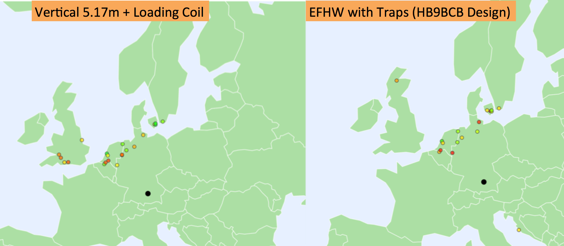
Date: March 31, 2018, 12:40 - 13:06 UTC Location: Sports field south of Munich, JN58, ca. 550 m ASL. Type of ground: Grass Antennas and Set Up:
a) EFHW with traps for 40-30-20 m, HB9BCB design, overall length ca. 16 m, Inverted Vee configuration at 6m mast, ends ca. 1 m AGL.
b) SOTA Superlight Vertical (description on Thingiverse), 5.17m radiator, single tuned radial sloping from feedpoint to ca. 10 cm AGL. Feedpoint ca. 40 cm AGL.
Both antennas were directed N-S with an angle of 13° North. The single radial of antenna b) was sloping northwards.
WSPR with 200mW
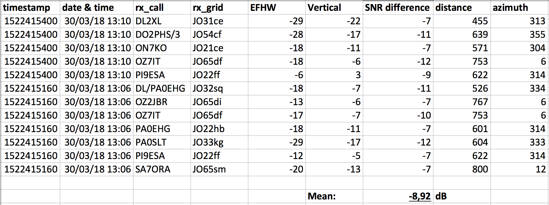
SWR for both was 1:1.35 or better. Results:
For simultaneous spots, the loaded vertical with the single radial outperformed the EFHW by 8.92 dB. This was really surprising but can likely be explained by the fact that the overlap of simultaneous spots was rather small (12 stations spotting both, as compared to 78 spots for the EFHW and 60 for the vertical.
Individually, the findings were pretty similar:
Distance of Spotting Stations:
a) EFHW Median: 602.5 km Max: 1420 km
b) Vertical Median: 604 km Max: 1053 km
SNR of Spotting Stations:
a) EFHW Median: -20 dB Max: -6 dB
b) Vertical Median: -17,5 dB Max: 5 dB
So from the median of SNR and distance, both antennas perform very similar. Keep in mind that this was on 40m where the vertical was only 1/9.67 lambda or roughly trivially 51% of 1/4 lambda.
We can see that the QRPguys concept, from which my design is derived, can indeed perform pretty well with a single but tuned and elevated radial.
I realize it’s a compromise but I don’t think it is as bad as you make it out to be. I have decent swr on 40, great swr on 30 and 20, and plenty of contacts. In fact the vertical does much better on 40m to the Southeast and western Great Lakes than my previous antenna, a trap dipole for 20 and 40.
If this were contesting then yeah, I wouldn’t prefer it but for SOTA its been rock solid, my contacts are up, my S2S are up, and I’m on the air in a jiffy. I’m going to keep using mine
Short verticals have lower resistive component and reactive component that is capacitive. To feed short vertical you need to get rid of the reactive part and increase the real part of the feed impedance to 50 ohms.
That requires loading and matching and with short verticals these can greatly impact efficiency. With the base loading coil you get rid of the reactive part and with what ever match you match the feed impedance to 50 ohms, the easiest way propably to do that is to use part of the loading coil as hairpin and connect the feed line so that the coil takes part of impedance matching also. Why people get close to 50 ohm match with single base loading coil/canceling the reactive part without impedance matching is because of added ground losses.
Good match does not of course mean good efficiency. When I installed radials under my 160m vertical array I measured the feed point impedance and it stopped changing (37 ohms) after I Installed some 40 radials and then I installed some 40 more just to be sure my ground losses are low. The starting feed point impedance was over 70 ohms indicating that I have too much ground losses, swr how ever was pretty OK. Matching 37 ohms to 50 ohms was done with L- match.
Vertical antenna efficiency = Rrad/(Rrad+Rloss) and with perfect ground ( Rloss=0 ohms) efficiency is perfect and with short verticals with good ground the efficiency is just perfect.
Short verticals are fun to build but difficult to match as many have noticed in this thread. Some sort of variable matching circuit makes matching much easier. The easiest way to modify that kit is to connect a small variable capacitor from coax connector center to ground for lower frequencies and create L- match.
maybe I sounded a bit too pessimistic, it will work great on 20m, well on 30m and make great contacts on 40m.
and sure is great antenna for many activations.
Your description of the input impedance and efficiency of the loaded vertical agrees with the antenna handbooks and my experiences of these antennas.
As many hams now own or can borrow very capable antenna analysers that can display the real and reactive components of an antenna’s impedance, it is interesting that no-one has published the measured parameters for the loaded vertical. The measurements would clarify the way it is working and end some of the conjecture.
in many practical cases the antenna feed line is part of antenna or matching circuit and that makes practical quick measurements of real and reactive components of any antenna a bit more challenging. Also the person who makes these measurements can quickly become a part of the antenna system and of course anything else around the antenna will affect measurements also.
What I would do is to model the antenna with some antenna analysis program and build the antenna and measure at the antenna feed point (with out the feed line) real and reactive components. I know that I would get very diffirent results because any antenna analysis software does not really know how to handle the real enviroment.
But I know I am too lazy to do all this. And I know the following facts:
Any antenna will radiate (if you can transfer power into it)
Some antennas are better and some worse
Any antenna is better than no antenna at all
If you are happy with your antenna and make qsos, that´s good!
If can´t get qsos from a summit, it might not be your antennas fault but in the end you have had a great day outdoors!
73 Marko OH3XR OH9XX
PS. I am using 20/30m vertical. I have 12 random radials (3-6m) on the ground (oh yes not optimum). The vertical part is 5.1 m (fishing pole). On 20m I leave 2.7m of the antenna wire hanging downwards and on 30m I just tie it some where (hiking pole, tree, rock) and then the antenna becomes a top loaded vertical. Because of the ground losses the antenna feed point impedance is good enough to transfer part of the power into radiation.
I don´t use any feed line and this antenna has served me well enough with 1 watts and it has no parts to break. All the credits go of course to all the chasers!
Unfortunately, it was not said that the low EFHW apex hight of 6m and its ends at 1m on 40m was only 0.17 lambda or “roughly trivially” 29% of 1/2 lambda!
Of course, everyone is free to choose what he wants to compare and ok, such a special comparison may be useful for your personal needs. However, the data collected for your trapped EFHW are not typical because the radiation characteristics are completely bent due to the low overall height. In addition a “SWR of 1.35 or better” does not say at all whether/where/how well an antenna radiates in which direction (horizontal and vertical diagrams!).
BTW, I recently read in a car magazine that a Land Rover was clearly superior to a Ferrari in the outback, but not on the highway…
Dear Heinz:
You know and I have said publicly many times that I really admire your EFHW design, and it is the antenna I use the most. The purpose of my analysis shown above was to evaluate by how much weaker my signals will be when I have to use my various loaded SOTA verticals under typical constraints. A typical constraint for me and likely many other activators is to use a mast of 6m or less, be they carbon-fiber or glass-fiber. The 10m masts I know and own (e.g. the one from SOTAbeams, which is equivalent to the DX-Wire mast) is way too long and too heavy for my activations. So yes, any full-size dipole, be it your design with traps, a linked dipole, or a single-band dipole, will hang too low for 40m.
But I do not think that renders my analysis useless or highly subjective, IMO.
The EFHW was tuned to resonance; the SWR check was just to make sure it had not been detuned. I actually think the 1.3x measurement was for the vertical and the EFHW was close to 1:1; my notes were not very readable wrt this.
Of course, the duration of the experiment was too short for a solid scientific evaluation. But it gives a good hint that indeed a short loaded vertical with a single tuned and elevated radial can radiate pretty well, which is also in line with what Gerd Janzen, DF6SJ, documented in his book.
Please also note that the single radial in my experiment was shortened and brought to resonance with the help of a 6 uH toroid-based loading coil, so both the radiator and the radial where close to 1/8 lambda.
I really do not understand why this antenna design is using shortest lenght on 20m band as basic resonant radiator and matching lower bands with big losses…inductance at the base. Bad grounding system, short radiator on 40/30m will cause big losses and bad results…