I previously had a Diamond X50 2m/70cm collinear at home which I connected to the 2m-70cm N type antenna port on my Yaesu FT857. My Off-Centre Fed Dipole (80m-10m) connects to the other (SO239) antenna port (160m-6m) on the 857.
I recently replaced the X50 with the Diamond V2000 6m/2m/70cm collinear to be QRV on 6m. This presents a connections problem as the 857 groups 6m in with the other HF bands. I can deal with this manually by either:
(a) using two 2-way antenna switches (3 switch combinations of which give me 80-10m OR 6m OR 2m/70cm) or
(b) moving the V2000 coax connector between the two ANT sockets on the 857 when using / finish using the 6m band.
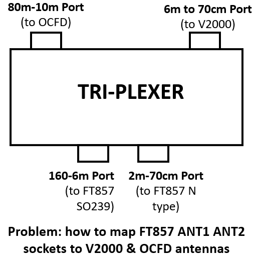
I would like an automated solution. Looking at commercial duplexers / triplexers I don’t see a single box solution. For example, the Diamond MX62M duplexer has [only] 3 ports. It maps 1.6-56 MHz to one port and 76-470 MHz to the other port. One UK dealer says it’s good for combining two rigs (e.g. rig1 6m and rig2 2m/70cm) to one antenna (e.g. my V2000 6/2/0.7 colinear) but that would mean no way to connect my OCFD at the same time.
Hi Andy,
I think you cant do this with just one Diplexer or Triplexor, as they only support the automated switching from one source to two or three outputs.
If the 857 puts out a different voltage depending upon which band you are on you could design a board that, using relays, could switch to the correct antenna from the correct input something similar to what this FA-AS box from FunkAmateur does for ICOM radios,
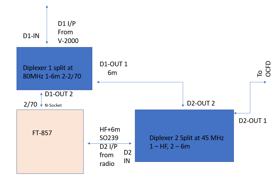
If you want to go passive, then you might be able to manage a solution using two diplexers.
One needs to split off 6 metres from the triband colinear - so that it splits at say 80MHz with 6m on one output port of the diplexer and 2m & 70cm on the other. The 2m/70cm output port would go to the N-type connector on the FT857.
A second diplexer instead of having its input from the antenna would have it from the FT857 SO239 socket - it would split at 45 MHz and one output port - the over 45MHz port, would connect to the empty (6m) output port on the first diplexer to use the v2000 on 6m. The other output port on this second diplexer would go to your OCFD for the HF bands.
The one worry I would have with this design would be RF from one of the antenna ports on the FT857 bleeding through back into the other FT857 antenna port however if the receiver inside the 857 is disconnected from both the antenna ports when the radio goes onto transmit, this should not be a problem - you will need to check the FT857 circuit diagram to see if this is the case.
You “might” be able to find suitable commercial diplexers for the required splits but it’s not difficult to build two diplexers yourself - here’s how I did this to split the output of my IC7300 between one antenna for 6 & 4 m and the other antenna for HF.
Thanks Ed - especially for your impressive diagram.
As well as your point about the ingress of RF with the two-duplexer solution, there will be a dB or two insertion loss with the 6m signal routing through two passband filters in the duplexers. The solution with relays should avoid that as does my current hand-operated 2-way antenna switches approach.
I’m not much motivated to design and build a relay-based solution which would consume much more time than I would actually operate on 6m from my outside shack. Most of my radio activity is SOTA portable and chasing from home is mainly when the weather is too bad for hill-walking and that doesn’t often overlap with the 6m band being open.
I had hoped there would be a ‘one box’ commercial product that does the job but the need is probably too small for any firm to justify productizing a solution.
Hi Andy,
I know of no commercial solution for Yaesu transcievers - as I say, The Box73 kit is only for ICOM as it uses the CiV protocol and the different band voltages that several ICOM radios produce.
If there is an all singing and dancing solution to switch antennas based on band in use on the radio, I expect someone like DX Engineering or MFJ would have the unit.
If you want simple and passive, (and commercially built), then the 2 x diplexer design that I drew may be possible if you can find the commercial diplexers who split on the right frequencies - but as you say, going through two diplexers as needed for 6m will add some loss.
Now if you were to use an 80m OCFD that covers 6 metres (many of them do) - then you would not need any switching at all.
Here’s an example of an OCFD for 80m-6m.
Have you tried using your existing 80m OCFD on 6 metres or is it 6m FM (hence vertical) that you are trying to achieve?
My OCFD does work to some extent on 6m despite it not being designed for 50MHz.
Given the physical constraints of locations for the antenna wire end supports relative to the outside shack and the current balun and feeder, my third redesign of the OCFD to the existing 79%-21% ratio wire legs version works pretty well on 80-10m including 60m [Described on another SOTA thread] so I’m not going to attempt to change it again.
With the 6m FT8 frequency and some eastern and southern 6m beacons programmed into my FT857 I routinely checked them using the OCFD. If nothing, I conclude 6m is closed and don’t bother to switch to the V2000 collinear.
I’ve worked many CW [and a few SSB] stations from all corners of EU on the V2000 on those rare occasions I’ve been in the shack and 6m was open.
Having gone to all the trouble of getting and installing the V2000 [on my chimney] and now getting and giving good reports on 6m with it, I’m definitely not inclined to change my [otherwise] fine OCFD to embrace an automated antenna switching in lieu of my current manually-switched one.
OK, another idea - could you add a 79/21 off-centre-fed 6m dipole to the existing feed point on the 80-10m OCFD a’la “fan dipole”. I know this is normally done only on centre-fed dipoles - it may not work on OCFs - but if you have easy access to the balun, it may be worth a try.
For CW, digital or SSB on 6 metres, IMHO, you are reducing your chances by using the co-linear. If you want 6m FM, then the colinear is the better option.
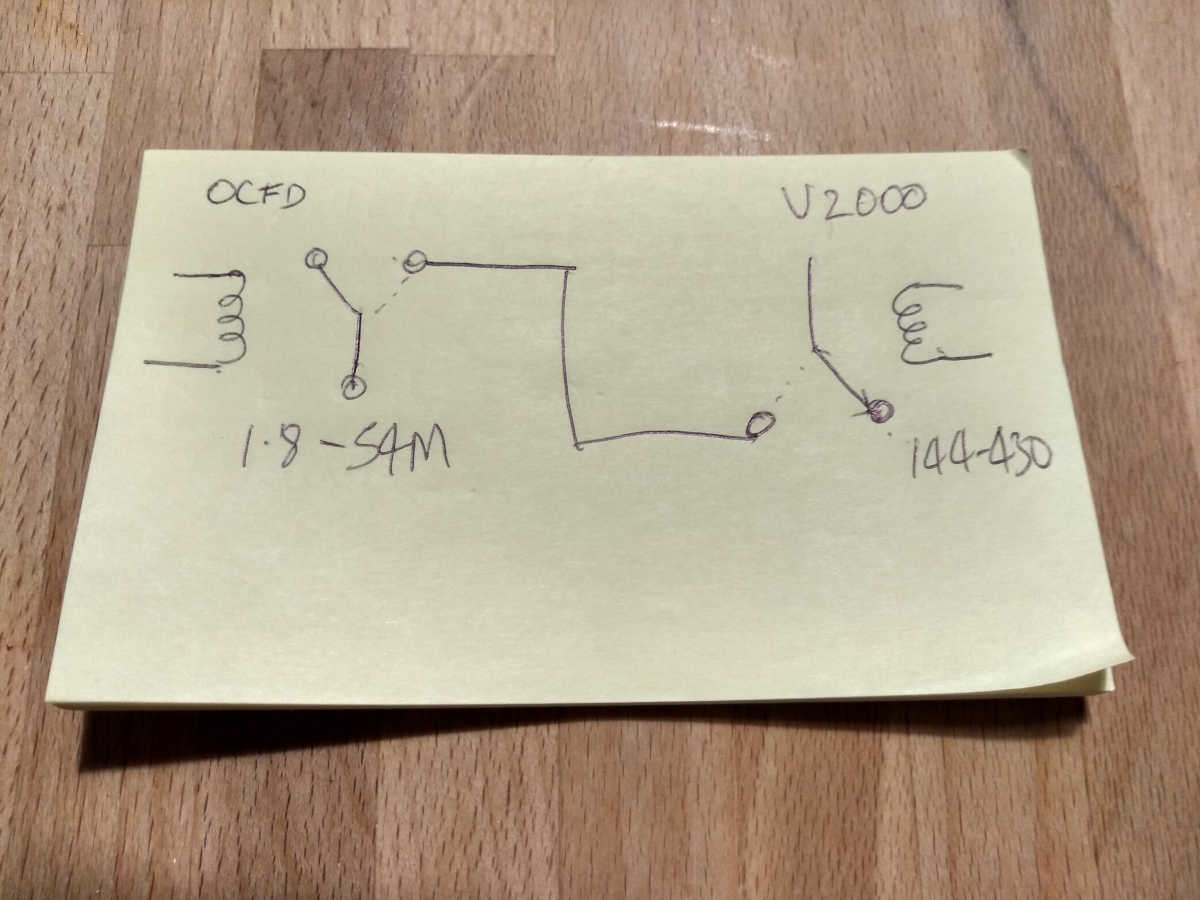
Andy, I think the way to do this is with a pair of RF change over relays and a comparator or two on the “band” voltage on the 857 ACC socket.
One relay switches VHF to the V2000 or disconnects the VHF output from the 857. Only connects VHF to V2000 when 2m/70cms selected.
Other relay handles HF and 6m and one output connects HF to the OCFD. When 6m detected it switches the relay and 6m goes to the other relay. That also switched disconnecting VHF port from radio and 6m to V2000.
You need a comparator to spot when 6m selected otherwise relays are not switched. Plus something to drive the relay coil (BFY51 & IN4001). And a pair of 100W RF relays. Probably there are some nice cheap PCB mount types you can use that end up being used in auto ATUs.
The relays will switch as you select bands and that will be when on receive. It wont easily handle split band or full duplex working without a delay to lock out TX when relays changing.
Should have less loss than a collection of diplexers. I’ll sketch it if you want.
The FT857-D UM isn’t very helpful in describing the function of some socket pins but I wonder if you meant the CAT/Linear socket [and not the ACC socket] which has a BAND-DATA pin for external ATU or pins Band-A, Band-B, Band-C and Band-D for control of a linear amp - intriguing but unexplained.
My mistake, I didn’t realise the 857 had different signals compared with the 817. The 817 has a BAND signal which is a voltage that varies between 0.33V and 4.00V depending which band the radio has selected. As you say the 857 has BAND A,B,C,D and no explanation. I looked at the service manual and circuits and I noticed that the 857 has 4 internal filter sets 1.8-28, 50-54, 144-148 and 430-450 and I’d put money on Band A being asserted when you select 1.8-28 and Band B for 50-54 etc. But I don’t have an 857 to test… someone would need to measure the voltage on the Band A B C D signal pins as the bands are selected to confirm that is the case.
So lets assume Band B gets asserted when 6m is selected and it goes “high” and is 0V the rest of the time. We can use that to drive a transistor and use the transistor to drive the relay coils. In the quick sketch, both relays are in parallel so they both change over when the transistor is driven. The contacts are show in the normally closed state.
The relay on the left has the common connected to the 857’s 1.8-54MHz antenna socket, the NC goes to the OFCD, the NO contact goes to the other relay NO contact. On the other relay the common goes to the V2000 and the NC goes to the 857’s 144-430MHz antenna socket.
Again assuming my Band A B C D signaling is correct… when any band other than 6m is selected, the HF antenna is connected to the HF socket on the 857 and the VHF/UHF antenna is connected to the VHF/UHF socket. When you select 6m, Band B is active, that drives the transistor which energises both relays. Now the HF socket is connected to the NO contact, through the wire to the other relay NO contact. That is now connected to the common and thus the 6m signal to/from the 1.8-50MHz socket is connected to the V2000.
Depends on my interpretation of the Band B etc. being correct. Fine details of the transistor and relay back emf protection omitted for now.
Does that seem reasonable? I’ve had a hard day and am on my 3rd Estrella Damm
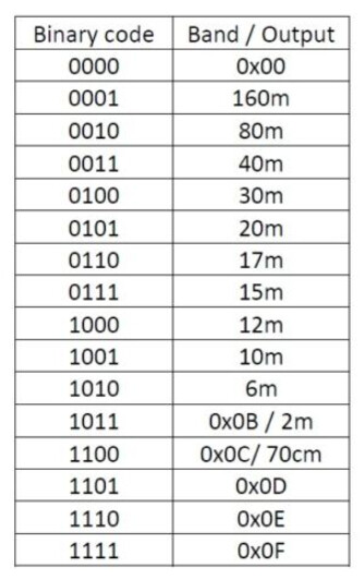
I must be getting old as I never considered the band data would be BCD. Or I could blame the Estrella !
If you just want to decode the data then the MC14514B is a BCD to 16 line decoder (with transparent latch) that will run off 3 to 18V that will do the decode and is (was) available as 24pin DIP package. Its outputs are active high whereas the MC14515B is the active low version. Gosh real electronics like the type I did 40+ years ago…no damn software needed