HF POWER AMPLIFIER MICRO PA 50

Another update. I tried replacing the UHF connectors with BNC connectors both mounted to an aluminum plate I built. Everything worked fine with a pure resistive load, but then the amp went CRAZY with an antenna attached. Suspecting that the input and output are not meant to share a ground, thus the aluminum plate I had connecting the grounds of the input and output connectors was the problem, I took that mod out and replaced the UHF connectors. It’s still lost its mind. Still works into resistive loads, but now it cannot be hooked to any antenna in any configuration. It reads wildly inaccurate SWR and power levels. I obviously broke something, just not sure what I broke.

FWIW, the multimeter reads continuity on the circuit board between the ground of the input and output connectors, but I’m not sure if that DC continuity is also AC continuity. I still suspect I busted something by connecting the grounds on those two connectors. Or I clumsily overheated a component with my soldering iron or broke something manhandling the circuit board out of the enclosure. Endless list of possibilities for how I screwed this up.

If you’re going to replace the connectors with BNC, be careful!

1 Like

Hi

Thanks for the warning, but done, and working just fine

I used the same idea of an internal ali mounting plate, secured by a central self-tapping screw to the back plate. I didn’t remove the board, just worked carefully to remove and reinstall the connectors.

One problem was that the BNC’s I had to hand penetrated a little deep towards the board so there was a risk of the connector casing shorting to the pad on the board. I resolved this by padding the connector with a 10mm washer - the ones I had to hand happened to be copper brake hose crush washers.

Result looks ok …

Rick

3 Likes

Thanks for sharing! I’ve got mine working now with R36 shorted to ground, therefore completely disabling the SWR protection. I’ll just have to be really careful with it now. I’ll reinstall my BNC connectors when I get home and test it out. Will post pictures of my implementation when I’m done. I’m starting to learn a lot about how this thing works just because I’ve spent so much time probing around in it with the oscilloscope. I found the schematic for the amplifier that’s at the core of this thing: IRF530 30w Mosfet Amplifier – F5NPV – V85NPV From the schematic, I can see that the input and output are meant to share a ground. So, obviously my SWR freakout is caused by some other defective component or something. Regardless, I feel like even if I blow up the finals, they’re easy to replace, so I’m not too concerned. Looking forward to having BNC connectors on this.

1 Like

Here’s my bnc mod:

2 Likes

Neat job.

It would be so much better if all low power (<400w) devices used BNC (in and out). I have BNC adaptors on all my gear, apart from the Elecraft kx3 and some vhf gear.

73 Andrew VK1DA/VK2DA

4 Likes

I couldn’t agree more. I don’t understand why UHF connectors persist. They’re inferior in almost every way!

2 Likes

Hi guys,

I confirm the SWR issue at my PA50 too. The problem starts only with a real antenna, with a dummy load all looks ok. Up to 20m all is ok, start with 17m up to 10m the SWR problem begun if I use a real (but resonant) antenna or my home antenna which is tuned by a CG3000 outdoor (SWR ever < 1.3 after tuning). I do the R36 mod too, but I haven’t a SMD resistor with 4k7 too :wink: I use a 10k through-hole resistor parallel to the R36. After this mod I can confirm, the shown SWR looks more correctly compared to an external SWR meter.
Here my pic for this mod (looks not very nice, but it works :slightly_smiling_face:):

Later I will be change the R36 with a SMD 4k7 resistor.

73 Heiko, DL1BZ

2 Likes

Hi guys,

I tested something else and made comparisons with my external SWR meter. I think, 5k ist not enough at R36. More a value between 1k5…2k2. I remove the R36 SMD resistor now completely and replace it with a 10k spiral potentiometer for better adjustment:

After this I repeat some SWR measurements and play around a little bit with the values. At the end I found 1k5 as best compromise. I have results near reality at 20m-10m and between, but at the low bands 80m-30m the shown SWR is a little bit to low than it should be, but not so much.
I use the PA50 more for portable so it is more important that the function is better above 10Mhz than lower.
In general I think, it would have been better if the protection was only effective from an SWR of 2.5 or 3 and not already start with only 2.0 . I’m sure, that would not be a problem for the finals, the most TRX do it so.
At the end I wouldn’t say “Don’t buy this amplifier”. We are hamradio operators and can solve such problems themselves. Aside from the SWR issue, it’s a good amp I think and a good add-one for portable.

For more comfort I build with an ESP32 (TTGO T-DISPLAY) a small device, which makes a Blutooth connection between the ESP32 and my IC-705, get it’s CAT data and switch the PA on/off with a 4N25 and generate an analog band switching signal for automatic switch the band filters in the PA (the IC-705 has no bandswitching output):

I setup the PA50 for XIEGU band switch protocol for this. I’m not a friend of VOX-controlled amps :wink: .
The same I use with my second amp too, a XIEGU XPA125B, too.

73 Heiko, DL1BZ

4 Likes

Thanks for this, Barry. Do you happen to know the code for this size of SMD resistor? I am a surface mount noob - back when I was a lad everything was enormous and soldering was like agriculture

1 Like

The resistor I used was one from my “Junk” box. I bought a whole lot of SMD resistors from ebay for various projects. I think it was an 0805 size component. 2mm long by 1.2mm wide.

1 Like

Now 4 activations using this amp and it’s working very well after the mods
I’m usually running 2.5W input from the FT-817 and sharing a 3Ah LIPO between the 817 and the amp

It certainly helps catching the S2S on 20M SSB …

Cheers
Rick

3 Likes

Yes thanks everyone in this thread. I had almost given up on this amp assuming there must be some strange common mode current thing or way off output impedance issue. The output impedance does seem to vary from 50ohms on some bands but now it’s not tripping out all the time I can poke out above the noise and catch the DX I was missing. 73 Hugh 9V1SA

3 Likes

I got my PA50 a few days ago and made the KD7QOW mod. I tried to use it with my KX3 but it seems that in the auto sensing mode at least, the two don’t play nice together. However, it works reasonably well with my Xiegu X6100. The input power it will tolerate varies significantly, from 1W on 80M to 4W on 17M (CW). I get 40-50W out, depending on the band. I’m still testing.
By the way, there is a translated manual on the Aliexpress website, though the file name is in English. The link below takes you to Dropbox and the file is there. Dropbox - all information - Simplify your life

2 Likes

Hello all. First post! I know this is an aging topic but I am curious if we have a general consensus regarding the best resister replacement or piggyback size / value for R36 to help with the hyper sensitive SWR issue. And if ya’ll decided to just replace the resister or run another in parallel with the original. That’s a two part question. Values please. (all bands are important to me :p)

I just received mine and the board number is v2.5 I will post pictures later today for you guys. Just a long shot, but maybe there is a HW change (wishful thinking)… I will check FW version when I take the pictures for this thread later tonight.

Thanks in advance…

1 Like

I have bought one of these recently. I was planning to do the resistor mod, but I’ve not opened it up yet. It has, however, worked straight out of the box with my 20/40m sotabeams linked dipole with no SWR problems. I had a few teething issues getting the unit to auto-switch to TX (which I think was down to me anyway), but so far am impressed with it (it does feel to be good value for money).

73s

Dave.

1 Like

HW rev: 2.5.6
FW rev: 2.1
Here are the pictures (I took many more if you need them uploaded, let me know):


Standing by for answers to the questions in my prior post.
Thanks in advance!

1 Like

Bump anyone? I hope my bump doesn’t get me in hot water…

As per the posts, parallel it with a 10k.

2 Likes

I made some additional measurements of the PA50. One result was a bad IM3, which was only
at -15…-20dbc. Thats too low, if you use the amplifier in SSB you will - maybe - get a bad, distorted signal.
After tests with some OM the problem was confirmed, especially at 80m. This is not a problem with too much input, lower input doesn’t solve the problem !

Here my solution:


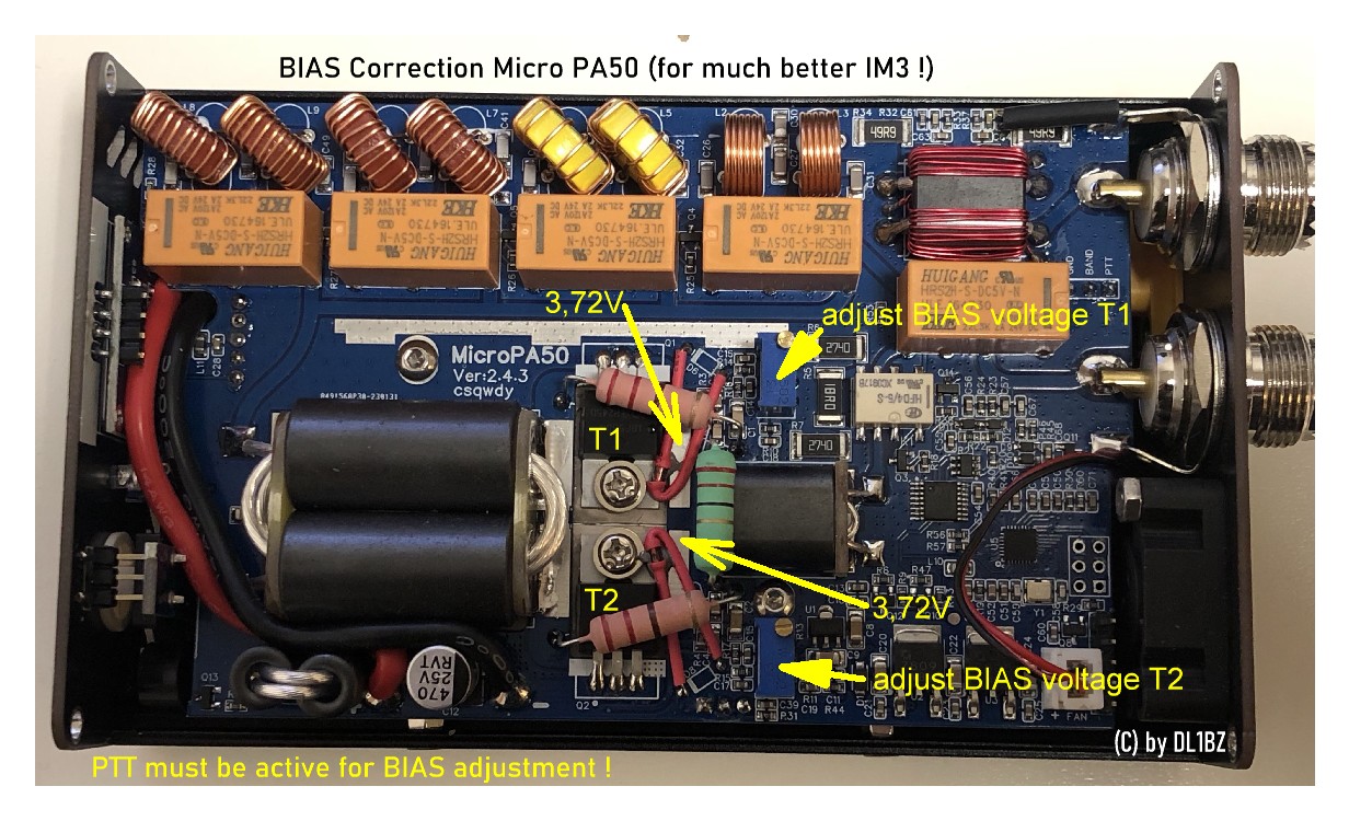
Adjust the BIAS up to 3.72V for both IRF530N transistors (PTT must be active for adjustment). After this adjustment I got now an IM3 of -35…-40dbc. That is much better, not perfect, but now the signal in SSB is ok and clear. Don’t try to get more output as 50W. The IRF530N are not RF transisitors, but work for this little power amplifier.Tests after the modification now confirmed a largely clean signal without distortion.

My solution has already been examined in detail here IRF530 30w Mosfet Amplifier – F5NPV – V85NPV and here PD7MAA HOMEPAGE: DIY kits 70W SSB linear HF Power Amplifier For YAESU FT-817 KX3 , the PA50 has a very similar concept.

I agree with PD7MAA, as he wrote:
“At 3 Watt input the output was about 50 Watt at 20m. But the modulation was as expected distorded in ssb mode at the recommended 2.7V bias voltage. At 3.7V ( gate ) bias the modulation is acceptable but far from perfect.”.

Before my adjustment I measure 3.57V BIAS from factory, where I need to agree, this is too low for a good signal in SSB. Now I’m happy and satisfied with this little amplifier.

73 Heiko, DL1BZ

2 Likes

Come across this by accident but After trying to use this amp with an swr of 1.5 to 1.6 on my antenna but this showing 2+ and then going into Looney mode all the time I managed with a small antenna to use it but only at 20 W this antenna was resonant 1.1 , the fan sounding like a jet engine i took the top of and pulled the plug in the fan , so how long will it take on ft8 for the amp to over heat surprisingly quite awhile at 20 W but the remarkable thing was the SWR came right down matching that On the ATU plugged the fan back in SWR goes up . anyway, short story long putting the fan on the outside the SWR now that I’ve replaced the fan with a 30cm Sunon 12v the swr is fine on all bands matching or least close to the ATU

1 Like