As per the posts, parallel it with a 10k.
I made some additional measurements of the PA50. One result was a bad IM3, which was only
at -15…-20dbc. Thats too low, if you use the amplifier in SSB you will - maybe - get a bad, distorted signal.
After tests with some OM the problem was confirmed, especially at 80m. This is not a problem with too much input, lower input doesn’t solve the problem !
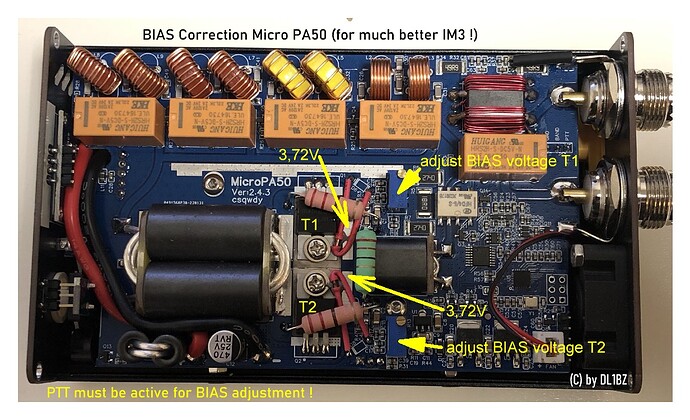
Here my solution:
Adjust the BIAS up to 3.72V for both IRF530N transistors (PTT must be active for adjustment). After this adjustment I got now an IM3 of -35…-40dbc. That is much better, not perfect, but now the signal in SSB is ok and clear. Don’t try to get more output as 50W. The IRF530N are not RF transisitors, but work for this little power amplifier.Tests after the modification now confirmed a largely clean signal without distortion.
My solution has already been examined in detail here IRF530 30w Mosfet Amplifier – F5NPV – V85NPV and here PD7MAA HOMEPAGE: DIY kits 70W SSB linear HF Power Amplifier For YAESU FT-817 KX3 , the PA50 has a very similar concept.
I agree with PD7MAA, as he wrote:
“At 3 Watt input the output was about 50 Watt at 20m. But the modulation was as expected distorded in ssb mode at the recommended 2.7V bias voltage. At 3.7V ( gate ) bias the modulation is acceptable but far from perfect.”.
Before my adjustment I measure 3.57V BIAS from factory, where I need to agree, this is too low for a good signal in SSB. Now I’m happy and satisfied with this little amplifier.
73 Heiko, DL1BZ
Come across this by accident but After trying to use this amp with an swr of 1.5 to 1.6 on my antenna but this showing 2+ and then going into Looney mode all the time I managed with a small antenna to use it but only at 20 W this antenna was resonant 1.1 , the fan sounding like a jet engine i took the top of and pulled the plug in the fan , so how long will it take on ft8 for the amp to over heat surprisingly quite awhile at 20 W but the remarkable thing was the SWR came right down matching that On the ATU plugged the fan back in SWR goes up . anyway, short story long putting the fan on the outside the SWR now that I’ve replaced the fan with a 30cm Sunon 12v the swr is fine on all bands matching or least close to the ATU
I flashed with version 1.5-beta. In it the software version PA author has changed the algorithm of SWR and power estimation to more integral, and also you can also disable SWR cut-off in “no limit” mode. The mode is memorised, as I understood. It is possible to operate the device. I worked 2 periods on air, about 20 QSO-s, flight is good.
Before that I was ready to throw it in the waste basket )
Hi,
Could you provide a link to the beta software you used, please?
TIA,
Dave
G7SAT
Hi!
https://drive.google.com/drive/folders/1TcL7LxupOFf8QJf6IQU32sE9mprPvSss
PS
I also unwound 3 coils from the output binoculars. I’m not sure if it helped much. With a real SWR of 1.05-1.1 (tuned InvV with a good balun) the readings on the PA are 1.2-1.3
Please report back on the result if.
Change log for beta, auto translation:
2024-07-10:b 1.5
Modify PWR and SWR filter weights
Modify PWR peak hold algorithm
Adjust the low voltage alarm value to 9.6V
Automatically wake up the screen display if the band is switched or any alarm is triggered.
2024-07-08:B 1.4
Add the function of automatically closing the display, the number of keystrokes is 11, and the display will be closed automatically after 1 minute after opening the display.
Modify the half-insertion delay parameter increment to 100ms, greater than 1000ms increment 500ms, maximum value 2000ms.
Optimise the display code to reduce memory consumption
2024-07-01:B 1.3
Unlimited mode no longer protects SWR.
Save unlimited mode to EEPROM
2024-06-30:B 1.2
Fix a calculation error
2024-06-30:B 1.1
Modifications to the high standing wave detection process as suggested by Marat, the enthusiast:
1, stop amplification immediately after detecting high standing wave and keep detecting it for 3 seconds, if after 3 seconds the radio is in continuous TX and still high standing wave, it will be protected. Otherwise the amplification of the amplifier will be turned on again.
2, If the radio stops TX within 3 seconds, the standing wave will be detected again.
Thank you very much!
Hi Heiko,
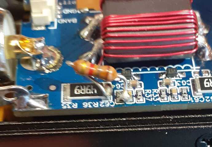
Thanks for the information you have gathered. I tried to put a 1k8 resistor in parallel and the result is just as you described, at 40 and 80 meters it detects a little less stationary, 1.5 of SWR reads 1.2, while in the high bands everything is ok and it no longer intervenes alarm unnecessarily. I recommend everyone to make this change, below is the photo of my intervention.
Hi all,
I would like to try to install the new Beta firmwares to try the new features.
Can anyone suggest the hardware and software to use?
Thanks.
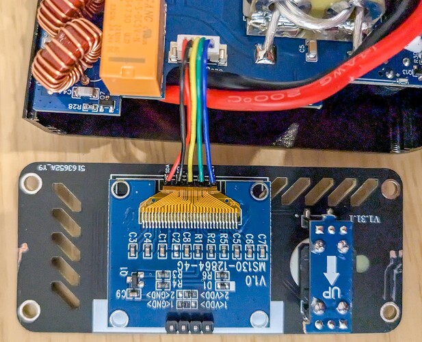
Can anyone on this forum provide me a picture of the front panel of the micro pa50 plus .
I accidentally broke the wires off and have been unable to determine the proper connections.
Also with regard to setting up the bias voltage, is there a certain mode AM FM SSb that should be used and keyed up while checking for proper voltage… recently blew the transistors replaced them it’s working but I want to validate proper voltages as noted in the articles above. I’m a newbie need help from the brain trust
AD9BX
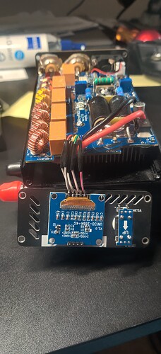
Do you mean a photo from the inside? I can take mine apart and take one but if you can describe what wires have come off from where it would help.
Having looked inside it must be these wires. They are attached in the same order they are in at the plug into the main board.
Thanks that’s what I needed.
I wonder why wires were used instead of a ribbon cable?


